Product Guide
Page 5
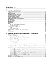
...Board Components Before You Begin 23 Installation Precautions 25 Prevent Power Supply Overload 25 Observe Safety and Regulatory Requirements 25 Installing the I/O Shield 26 Installing and Removing the Desktop Board 27 Installing and Removing Memory 27 Installing DIMMs 28 Removing DIMMs 30 Connecting SATA Drives 30... Installing a Wireless LAN Card in the PCI Express Full-Mini Card Slot 32 Installing an Intel® Z-U130 USB Solid-State Drive (or Compatible Device 33 Connecting to the Internal Headers 34 Connecting the Front Panel Audio ...
...Board Components Before You Begin 23 Installation Precautions 25 Prevent Power Supply Overload 25 Observe Safety and Regulatory Requirements 25 Installing the I/O Shield 26 Installing and Removing the Desktop Board 27 Installing and Removing Memory 27 Installing DIMMs 28 Removing DIMMs 30 Connecting SATA Drives 30... Installing a Wireless LAN Card in the PCI Express Full-Mini Card Slot 32 Installing an Intel® Z-U130 USB Solid-State Drive (or Compatible Device 33 Connecting to the Internal Headers 34 Connecting the Front Panel Audio ...
Product Guide
Page 7
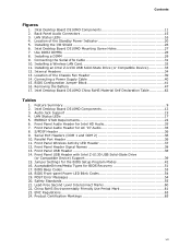
...Header for the BIOS Setup Program Modes 42 16. S/PDIF Header 36 9. Front Panel Header Signal Names 38 13. Jumper Settings for Intel HD Audio 35 7. AcceptableDrives/Media Types for AC '97 Audio 35 8. Lead-Free Second Level Interconnect Marks 60 22. Product Certification Markings...Summary 9 2. Parallel Port Header 36 11. POST Error Messages 54 20. Installing the I/O Shield 26 6. Installing a DIMM 29 9. Serial Port Headers (COM 1 and COM 2 36 10. Front Panel USB Header with Intel Z-U130 USB Solid-State Drive (or Compatible Device) Support 39 15. Safety Standards 55 ...
...Header for the BIOS Setup Program Modes 42 16. S/PDIF Header 36 9. Front Panel Header Signal Names 38 13. Jumper Settings for Intel HD Audio 35 7. AcceptableDrives/Media Types for AC '97 Audio 35 8. Lead-Free Second Level Interconnect Marks 60 22. Product Certification Markings...Summary 9 2. Parallel Port Header 36 11. POST Error Messages 54 20. Installing the I/O Shield 26 6. Installing a DIMM 29 9. Serial Port Headers (COM 1 and COM 2 36 10. Front Panel USB Header with Intel Z-U130 USB Solid-State Drive (or Compatible Device) Support 39 15. Safety Standards 55 ...
Product Guide
Page 17
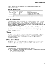
...back panel and three ports routed to the cable. USB 2.0 Support The Desktop Board supports up and the LAN subsystem is operating. Use a shielded cable that support one device per channel. Expandability The Desktop Board provides the following expansion capability: • One PCI connector. The connector can...operate in card or a single- NOTE Computer systems that fully support USB 2.0 transfer rates. One of the front panel USB headers supports an Intel Z-U130 USB Solid-State Drive (or compatible device). or dual-slot PCI riser card. • One PCI Express Full-Mini Card slot. 17...
...back panel and three ports routed to the cable. USB 2.0 Support The Desktop Board supports up and the LAN subsystem is operating. Use a shielded cable that support one device per channel. Expandability The Desktop Board provides the following expansion capability: • One PCI connector. The connector can...operate in card or a single- NOTE Computer systems that fully support USB 2.0 transfer rates. One of the front panel USB headers supports an Intel Z-U130 USB Solid-State Drive (or compatible device). or dual-slot PCI riser card. • One PCI Express Full-Mini Card slot. 17...
Product Guide
Page 23
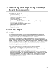
...before performing any procedures can damage components. 2 Installing and Replacing Desktop Board Components This chapter tells you how to: • Install the I/O shield • Install and remove the Desktop Board • Install and remove system memory • Connect SATA drives • Install a Wireless ...LAN card • Install an Intel Z-U130 USB Solid-State Drive (or compatible device) • Connect to internal headers • Connect chassis fan and power supply cables ...
...before performing any procedures can damage components. 2 Installing and Replacing Desktop Board Components This chapter tells you how to: • Install the I/O shield • Install and remove the Desktop Board • Install and remove system memory • Connect SATA drives • Install a Wireless ...LAN card • Install an Intel Z-U130 USB Solid-State Drive (or compatible device) • Connect to internal headers • Connect chassis fan and power supply cables ...
Product Guide
Page 26
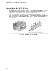
...and securely. Intel Desktop Board D510MO Product Guide Installing the I/O Shield The Desktop Board comes with an I /O shield before installing the Desktop Board in the chassis. When installed in Figure 5. Place the shield inside the chassis as shown in the chassis, the shield blocks radio ...frequency transmissions, protects internal components from the chassis supplier. If the shield does not fit, obtain a properly-sized shield from dust and foreign objects, and ...
...and securely. Intel Desktop Board D510MO Product Guide Installing the I/O Shield The Desktop Board comes with an I /O shield before installing the Desktop Board in the chassis. When installed in Figure 5. Place the shield inside the chassis as shown in the chassis, the shield blocks radio ...frequency transmissions, protects internal components from the chassis supplier. If the shield does not fit, obtain a properly-sized shield from dust and foreign objects, and ...
Product Guide
Page 32
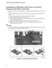
... the mounting holes (Figure 10, B) and snap the card in "Before You Begin" on page 23. 2. NOTE External antennas can be connected through the I/O shield by removing any or all of the cut-outs above the back panel I/O section. To install a wireless LAN card on the wireless LAN card as... antenna wires to the connectors (Figure 10, C) on the Desktop Board, see Figure 10 and follow these steps: 1. Observe the precautions in place. 5. Intel Desktop Board D510MO Product Guide Installing a Wireless LAN Card in the PCI Express Full-Mini Card Slot A wireless LAN card can be installed in the...
... the mounting holes (Figure 10, B) and snap the card in "Before You Begin" on page 23. 2. NOTE External antennas can be connected through the I/O shield by removing any or all of the cut-outs above the back panel I/O section. To install a wireless LAN card on the wireless LAN card as... antenna wires to the connectors (Figure 10, C) on the Desktop Board, see Figure 10 and follow these steps: 1. Observe the precautions in place. 5. Intel Desktop Board D510MO Product Guide Installing a Wireless LAN Card in the PCI Express Full-Mini Card Slot A wireless LAN card can be installed in the...

Product Guide
Page 64
...is household equipment that the power supply and other non-residential environments. Pay close attention to comply with EMC requirements. Intel Desktop Board D510MO Product Guide Korean Class B statement translation: This is certified to the following when reading the installation instructions...for the host chassis, power supply, and other modules: • Product certifications or lack of certifications • External I/O cable shielding and filtering • Mounting, grounding, and bonding requirements • Keying connectors when mating the wrong connectors could be hazardous If ...
...is household equipment that the power supply and other non-residential environments. Pay close attention to comply with EMC requirements. Intel Desktop Board D510MO Product Guide Korean Class B statement translation: This is certified to the following when reading the installation instructions...for the host chassis, power supply, and other modules: • Product certifications or lack of certifications • External I/O cable shielding and filtering • Mounting, grounding, and bonding requirements • Keying connectors when mating the wrong connectors could be hazardous If ...