Product Guide
Page 5
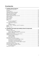
Contents 1 Desktop Board Features Desktop Board Components 11 Processor ...13 System Memory 13 Integrated Graphics Subsystem 14 Intel® NM10 Express Chipset 14 Operating System Support 14 Onboard Audio Subsystem 14 Legacy Input/Output (I/O) Controller 16 LAN Subsystem 16 ...Overload 25 Observe Safety and Regulatory Requirements 25 Installing the I/O Shield 26 Installing and Removing the Desktop Board 27 Installing and Removing Memory 27 Installing DIMMs 28 Removing DIMMs 30 Connecting SATA Drives 30 Connecting to the Internal Headers 32 Connecting the Front Panel Audio Header...
Contents 1 Desktop Board Features Desktop Board Components 11 Processor ...13 System Memory 13 Integrated Graphics Subsystem 14 Intel® NM10 Express Chipset 14 Operating System Support 14 Onboard Audio Subsystem 14 Legacy Input/Output (I/O) Controller 16 LAN Subsystem 16 ...Overload 25 Observe Safety and Regulatory Requirements 25 Installing the I/O Shield 26 Installing and Removing the Desktop Board 27 Installing and Removing Memory 27 Installing DIMMs 28 Removing DIMMs 30 Connecting SATA Drives 30 Connecting to the Internal Headers 32 Connecting the Front Panel Audio Header...
Product Guide
Page 6
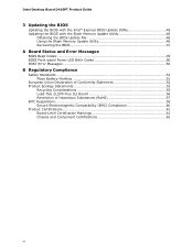
... D410PT Product Guide 3 Updating the BIOS Updating the BIOS with the Intel® Express BIOS Update Utility 45 Updating the BIOS with the Iflash Memory Update Utility 46 Obtaining the BIOS Update File 46 Using the Iflash Memory Update Utility 46 Recovering the BIOS 47 A Board Status and Error Messages BIOS Beep Codes...
... D410PT Product Guide 3 Updating the BIOS Updating the BIOS with the Intel® Express BIOS Update Utility 45 Updating the BIOS with the Iflash Memory Update Utility 46 Obtaining the BIOS Update File 46 Using the Iflash Memory Update Utility 46 Recovering the BIOS 47 A Board Status and Error Messages BIOS Beep Codes...
Product Guide
Page 9
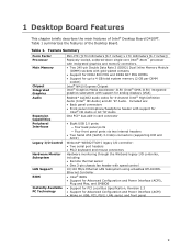
...[6.7 inches] x 170 millimeters [6.7 inches]) Passively-cooled, soldered-down single-core Intel® Atom™ processor with integrated graphics and memory controllers. • Two 240-pin Double Data Rate 2 (DDR2) Dual Inline Memory Module (DIMM) sockets with gold-plated contacts • Support for DDR2 800 ...MHz and DDR2 667 MHz DIMMs • Support for up to 4 GB total system memory (2 GB per DIMM socket) Intel® NM10 Express Chipset Intel® Graphics Media Accelerator 3150 (Intel® GMA 3150) integrated graphics subsystem with speed control 10/100 Mb/s Ethernet LAN Subsystem...
...[6.7 inches] x 170 millimeters [6.7 inches]) Passively-cooled, soldered-down single-core Intel® Atom™ processor with integrated graphics and memory controllers. • Two 240-pin Double Data Rate 2 (DDR2) Dual Inline Memory Module (DIMM) sockets with gold-plated contacts • Support for DDR2 800 ...MHz and DDR2 667 MHz DIMMs • Support for up to 4 GB total system memory (2 GB per DIMM socket) Intel® NM10 Express Chipset Intel® Graphics Media Accelerator 3150 (Intel® GMA 3150) integrated graphics subsystem with speed control 10/100 Mb/s Ethernet LAN Subsystem...
Product Guide
Page 13
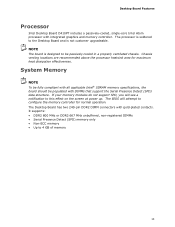
... gold-plated contacts. The Desktop Board has two 240-pin DDR2 DIMM connectors with DIMMs that support the Serial Presence Detect (SPD) data structure. System Memory NOTE To be fully compliant with all applicable Intel® SDRAM memory specifications, the board should be passively cooled in a properly ventilated chassis. Desktop Board Features Processor...
... gold-plated contacts. The Desktop Board has two 240-pin DDR2 DIMM connectors with DIMMs that support the Serial Presence Detect (SPD) data structure. System Memory NOTE To be fully compliant with all applicable Intel® SDRAM memory specifications, the board should be passively cooled in a properly ventilated chassis. Desktop Board Features Processor...
Product Guide
Page 23
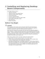
... panel power button is not available, you how to: • Install the I/O shield • Install and remove the Desktop Board • Install and remove system memory • Connect SATA drives • Connect to internal headers • Connect chassis fan and power supply cables • Set the BIOS configuration jumper • Clear...
... panel power button is not available, you how to: • Install the I/O shield • Install and remove the Desktop Board • Install and remove system memory • Connect SATA drives • Connect to internal headers • Connect chassis fan and power supply cables • Set the BIOS configuration jumper • Clear...
Product Guide
Page 24
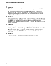
... DIMM. Failure to do so could cause components to the board. Intel makes no warranties or representations that the ambient temperature does not exceed the board's maximum operating temperature. Intel Desktop Board D410PT Product Guide CAUTION Failure to ensure appropriate airflow may result.... Chassis venting locations are recommended over the processor, voltage regulator, and system memory areas for determining the adequacy of both the processor and/or voltage regulator or, in the Intel Desktop Board Technical Product Specification. Ensure that proper airflow is required for the ...
... DIMM. Failure to do so could cause components to the board. Intel makes no warranties or representations that the ambient temperature does not exceed the board's maximum operating temperature. Intel Desktop Board D410PT Product Guide CAUTION Failure to ensure appropriate airflow may result.... Chassis venting locations are recommended over the processor, voltage regulator, and system memory areas for determining the adequacy of both the processor and/or voltage regulator or, in the Intel Desktop Board Technical Product Specification. Ensure that proper airflow is required for the ...
Product Guide
Page 27
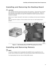
... and removing the Desktop Board. The Desktop Board has two 240-pin DDR2 DIMM sockets. 27 Intel Desktop Board D410PT Mounting Screw Holes Installing and Removing Memory NOTE To be fully compliant with all applicable Intel SDRAM memory specifications, the boards require DIMMs that support the Serial Presence Detect (SPD) data structure. Refer to...
... and removing the Desktop Board. The Desktop Board has two 240-pin DDR2 DIMM sockets. 27 Intel Desktop Board D410PT Mounting Screw Holes Installing and Removing Memory NOTE To be fully compliant with all applicable Intel SDRAM memory specifications, the boards require DIMMs that support the Serial Presence Detect (SPD) data structure. Refer to...
Product Guide
Page 39
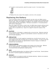
..., hvis batteriet erstattes med et batteri af en forkert type. Replacing the Battery A coin-cell battery powers the Desktop Board's real-time clock and CMOS memory. Brukte batterier bør kastes i henhold til gjeldende miljølovgivning. To restore normal operation, place the jumper on pins 1-2 as shown below a certain level, the...
..., hvis batteriet erstattes med et batteri af en forkert type. Replacing the Battery A coin-cell battery powers the Desktop Board's real-time clock and CMOS memory. Brukte batterier bør kastes i henhold til gjeldende miljølovgivning. To restore normal operation, place the jumper on pins 1-2 as shown below a certain level, the...

Product Guide
Page 45
... Download the file to a removable USB device. Follow the instructions provided in an automated update utility that combines the functionality of the Intel® Flash Memory Update Utility and the ease of use of Windows-based installation wizards. The BIOS file is included in the dialog boxes to view and...click the executable file from the location on your hard drive. (You can access the BIOS Setup program by either using the Intel Express BIOS Update utility or the Iflash Memory Update utility, and how to update the BIOS by pressing the key after the Power-On Self-Test (POST...
... Download the file to a removable USB device. Follow the instructions provided in an automated update utility that combines the functionality of the Intel® Flash Memory Update Utility and the ease of use of Windows-based installation wizards. The BIOS file is included in the dialog boxes to view and...click the executable file from the location on your hard drive. (You can access the BIOS Setup program by either using the Intel Express BIOS Update utility or the Iflash Memory Update utility, and how to update the BIOS by pressing the key after the Power-On Self-Test (POST...
Product Guide
Page 46
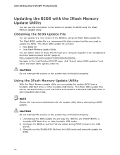
...can be extracted locally to your computer supplier or by using the Iflash Memory Update Utility. NOTE Review the instructions distributed with the Iflash Memory Update Utility You can obtain either of the BIOS by navigating to the Intel Desktop D410PT page, click "[view] Latest BIOS updates," and select the...BIOS or use the information in this section to update the BIOS. The Iflash BIOS update file contains: • New BIOS file • Intel Flash Memory Update Utility You can use the F10 key option during POST to boot to a bootable USB flash drive or other bootable USB media. 2....
...can be extracted locally to your computer supplier or by using the Iflash Memory Update Utility. NOTE Review the instructions distributed with the Iflash Memory Update Utility You can obtain either of the BIOS by navigating to the Intel Desktop D410PT page, click "[view] Latest BIOS updates," and select the...BIOS or use the information in this section to update the BIOS. The Iflash BIOS update file contains: • New BIOS file • Intel Flash Memory Update Utility You can use the F10 key option during POST to boot to a bootable USB flash drive or other bootable USB media. 2....
Product Guide
Page 49
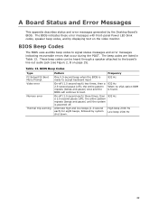
... to the board's line out audio jack (see Figure 2, B on the video monitor. BIOS Beep Codes Type F2 Setup/F10 Boot Menu Prompt Video error Memory error Thermal trip warning Pattern Frequency One 0.5-second beep when the BIOS is ready to boot. 932 Hz When no VGA option ROM is powered...
... to the board's line out audio jack (see Figure 2, B on the video monitor. BIOS Beep Codes Type F2 Setup/F10 Boot Menu Prompt Video error Memory error Thermal trip warning Pattern Frequency One 0.5-second beep when the BIOS is ready to boot. 932 Hz When no VGA option ROM is powered...

Product Guide
Page 50
... pattern repeats (blinks and pause) until the BIOS update is complete. POST Error Messages Error Message CMOS Battery Low CMOS Checksum Bad Memory Size Decreased No Boot Device Available Explanation The battery may be accompanied by system shut down. The pattern repeats until the system is ... second on the video monitor when certain recoverable errors occur during the POST. Each beep will be losing power. Memory size has decreased since the last boot. Intel Desktop Board D410PT Product Guide BIOS Front-panel Power LED Blink Codes The BIOS also blinks the front-panel power ...
... pattern repeats (blinks and pause) until the BIOS update is complete. POST Error Messages Error Message CMOS Battery Low CMOS Checksum Bad Memory Size Decreased No Boot Device Available Explanation The battery may be accompanied by system shut down. The pattern repeats until the system is ... second on the video monitor when certain recoverable errors occur during the POST. Each beep will be losing power. Memory size has decreased since the last boot. Intel Desktop Board D410PT Product Guide BIOS Front-panel Power LED Blink Codes The BIOS also blinks the front-panel power ...


