
Product Specification
Page 5
...11 1.1.3 Board Layout 12 1.1.4 Block Diagram 14 1.2 Online Support ...15 1.3 Processor ...15 1.4 System Memory ...16 1.4.1 Memory Configurations 17 1.5 Intel® 945P Chipset...21 1.5.1 USB ...21 1.5.2 IDE Support 22 1.5.3 Real-Time Clock, CMOS SRAM, and Battery 24 1.6 PCI Express Connectors 24 1.7 IEEE-1394a Connectors (Optional 24 1.8 Legacy I/O Controller 25 1.8.1 Serial Port...25 1.8.2 Parallel Port 25 1.8.3 Diskette Drive Controller 25 1.8.4 Keyboard and Mouse Interface 25 1.9 Audio Subsystem ...26 1.9.1 Audio Subsystem Software 26 1.9.2 Audio Connectors 26 1.9.3 6-Channel...
...11 1.1.3 Board Layout 12 1.1.4 Block Diagram 14 1.2 Online Support ...15 1.3 Processor ...15 1.4 System Memory ...16 1.4.1 Memory Configurations 17 1.5 Intel® 945P Chipset...21 1.5.1 USB ...21 1.5.2 IDE Support 22 1.5.3 Real-Time Clock, CMOS SRAM, and Battery 24 1.6 PCI Express Connectors 24 1.7 IEEE-1394a Connectors (Optional 24 1.8 Legacy I/O Controller 25 1.8.1 Serial Port...25 1.8.2 Parallel Port 25 1.8.3 Diskette Drive Controller 25 1.8.4 Keyboard and Mouse Interface 25 1.9 Audio Subsystem ...26 1.9.1 Audio Subsystem Software 26 1.9.2 Audio Connectors 26 1.9.3 6-Channel...

Product Specification
Page 6
... BIOS Features 3.1 Introduction ...71 3.2 BIOS Flash Memory Organization 72 3.3 Resource Configuration 72 3.3.1 PCI Autoconfiguration 72 3.3.2 PCI IDE Support 72 3.4 System Management BIOS (SMBIOS 73 3.5 Legacy USB Support...73 3.6 BIOS Updates ...74 3.6.1 Language Support 74 3.6.2 Custom Splash Screen 74 3.7 Boot Options ...75 3.7.1 CD-ROM Boot 75 3.7.2 Network Boot 75 3.7.3 Booting Without Attached Devices 75 3.7.4 Changing the Default Boot Device During POST 75 3.8 Adjusting Boot Speed 76 3.8.1 Peripheral Selection and Configuration 76 3.8.2 BIOS Boot Optimizations 76 3.9 BIOS...
... BIOS Features 3.1 Introduction ...71 3.2 BIOS Flash Memory Organization 72 3.3 Resource Configuration 72 3.3.1 PCI Autoconfiguration 72 3.3.2 PCI IDE Support 72 3.4 System Management BIOS (SMBIOS 73 3.5 Legacy USB Support...73 3.6 BIOS Updates ...74 3.6.1 Language Support 74 3.6.2 Custom Splash Screen 74 3.7 Boot Options ...75 3.7.1 CD-ROM Boot 75 3.7.2 Network Boot 75 3.7.3 Booting Without Attached Devices 75 3.7.4 Changing the Default Boot Device During POST 75 3.8 Adjusting Boot Speed 76 3.8.1 Peripheral Selection and Configuration 76 3.8.2 BIOS Boot Optimizations 76 3.9 BIOS...
Product Specification
Page 7
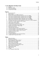
... BIOS Beep Codes...79 4.3 BIOS Error Messages 79 4.4 Port 80h POST Codes 80 Figures 1. Feature Summary ...10 2. Thermal Sensors and Fan Connectors 32 14. Board Components Shown in Figure 1 13 4. Effects of Pressing the Power Switch 33 8. DMA Channels ...41 12. Memory Channel and DIMM Configuration 17 4. Dual Channel (Interleaved) Mode Configuration with Four DIMMs 19 7. Board Dimensions...58 23. Front/Back Panel Audio Connector Options for Front Panel Connector 54 19. LAN Connector LED Locations 29 12. LAN Connector LED Locations 30 13. Connection Diagram...
... BIOS Beep Codes...79 4.3 BIOS Error Messages 79 4.4 Port 80h POST Codes 80 Figures 1. Feature Summary ...10 2. Thermal Sensors and Fan Connectors 32 14. Board Components Shown in Figure 1 13 4. Effects of Pressing the Power Switch 33 8. DMA Channels ...41 12. Memory Channel and DIMM Configuration 17 4. Dual Channel (Interleaved) Mode Configuration with Four DIMMs 19 7. Board Dimensions...58 23. Front/Back Panel Audio Connector Options for Front Panel Connector 54 19. LAN Connector LED Locations 29 12. LAN Connector LED Locations 30 13. Connection Diagram...
Product Specification
Page 8
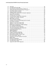
.... Intel Desktop Board D945PSN Technical Product Specification 14. PCI Interrupt Routing Map 46 16. BIOS Setup Configuration Jumper Settings 57 32. Safety Regulations ...66 37. BIOS Setup Program Function Keys 72 41. Port 80h POST Codes 81 47. Fan Connector Current Capability 61 34. Front Panel Audio Connector 50 19. Component-side Connectors Shown in Figure 16 47 17. Boot Device Menu Options 75 42. Typical Port 80h POST Sequence 84 viii States for a Two-Color Power LED 55 31. Processor Fan Connector...
.... Intel Desktop Board D945PSN Technical Product Specification 14. PCI Interrupt Routing Map 46 16. BIOS Setup Configuration Jumper Settings 57 32. Safety Regulations ...66 37. BIOS Setup Program Function Keys 72 41. Port 80h POST Codes 81 47. Fan Connector Current Capability 61 34. Front Panel Audio Connector 50 19. Component-side Connectors Shown in Figure 16 47 17. Boot Device Menu Options 75 42. Typical Port 80h POST Sequence 84 viii States for a Two-Color Power LED 55 31. Processor Fan Connector...
Product Specification
Page 10
...the board. BIOS Expansion Capabilities Instantly Available PC Technology Hardware Monitor Subsystem • Intel® BIOS (resident in the SPI Flash device) • Support for Advanced Configuration and Power Interface (ACPI), Plug and Play, and SMBIOS • Four PCI Conventional* bus connectors • Two PCI Express x1 bus add-in card connectors • One PCI Express x16 bus add-in card connector Audio 6-channel (5.1) audio subsystem with three analog audio outputs using the Sigmatel 9220 audio codec Legacy I/O Control Legacy I/O controller for diskette drive, serial, parallel...
...the board. BIOS Expansion Capabilities Instantly Available PC Technology Hardware Monitor Subsystem • Intel® BIOS (resident in the SPI Flash device) • Support for Advanced Configuration and Power Interface (ACPI), Plug and Play, and SMBIOS • Four PCI Conventional* bus connectors • Two PCI Express x1 bus add-in card connectors • One PCI Express x16 bus add-in card connector Audio 6-channel (5.1) audio subsystem with three analog audio outputs using the Sigmatel 9220 audio codec Legacy I/O Control Legacy I/O controller for diskette drive, serial, parallel...

Product Specification
Page 11
... security For information about Available configurations for RAID support (levels 0,1, 0+1, and 5) on the SATA interface SCSI Hard Drive Activity LED Connector Allows add-in all marketing channels. Product Description 1.1.2 Manufacturing Options Table 2 describes the manufacturing options. Manufacturing Options Auxiliary fan connector Additional fan connector for use in larger chassis IEEE-1394a Interface IEEE-1394a controller and three IEEE-1394a connectors (one back panel connector, two front-panel connectors) LAN subsystem The board provides one of the...
... security For information about Available configurations for RAID support (levels 0,1, 0+1, and 5) on the SATA interface SCSI Hard Drive Activity LED Connector Allows add-in all marketing channels. Product Description 1.1.2 Manufacturing Options Table 2 describes the manufacturing options. Manufacturing Options Auxiliary fan connector Additional fan connector for use in larger chassis IEEE-1394a Interface IEEE-1394a controller and three IEEE-1394a connectors (one back panel connector, two front-panel connectors) LAN subsystem The board provides one of the...
Product Specification
Page 14
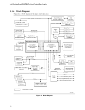
... Ethernet Controller (Optional) LAN Connector USB Back Panel/Front Panel USB Ports Legacy I/O Controller LPC Bus Serial Port Parallel Port PS/2 Mouse PS/2 Keyboard Diskette Drive Connector Intel 82801G I/O Controller Hub (ICH7) Serial Peripheral Interface (SPI) Flash Device DMI Interconnect High Definition Audio Link LAN Connect Interface Channel A DIMMs (2) Dual-Channel Memory Bus SMBus Channel B DIMMs (2) IEEE-1394a Connectors (optional) IEEE-1394a Controller (optional) PCI Bus PCI Bus PCI Slot 1 PCI Slot 2 PCI Slot 3 PCI Slot 4 SMBus Hardware Monitoring and Fan Control ASIC...
... Ethernet Controller (Optional) LAN Connector USB Back Panel/Front Panel USB Ports Legacy I/O Controller LPC Bus Serial Port Parallel Port PS/2 Mouse PS/2 Keyboard Diskette Drive Connector Intel 82801G I/O Controller Hub (ICH7) Serial Peripheral Interface (SPI) Flash Device DMI Interconnect High Definition Audio Link LAN Connect Interface Channel A DIMMs (2) Dual-Channel Memory Bus SMBus Channel B DIMMs (2) IEEE-1394a Connectors (optional) IEEE-1394a Controller (optional) PCI Bus PCI Bus PCI Slot 1 PCI Slot 2 PCI Slot 3 PCI Slot 4 SMBus Hardware Monitoring and Fan Control ASIC...

Product Specification
Page 16
... 667, DDR2 533, or DDR2 400 MHz SDRAM DIMMs NOTES • Remove the PCI Express x16 video card before installing or upgrading memory to correctly configure the memory settings, but performance and reliability may not function under the determined frequency. Intel Desktop Board D945PSN Technical Product Specification 1.4 System Memory The board has four DIMM sockets and support the following memory features: • 1.8 V (only) DDR2 SDRAM DIMMs with gold-plated contacts •...
... 667, DDR2 533, or DDR2 400 MHz SDRAM DIMMs NOTES • Remove the PCI Express x16 video card before installing or upgrading memory to correctly configure the memory settings, but performance and reliability may not function under the determined frequency. Intel Desktop Board D945PSN Technical Product Specification 1.4 System Memory The board has four DIMM sockets and support the following memory features: • 1.8 V (only) DDR2 SDRAM DIMMs with gold-plated contacts •...

Product Specification
Page 23
... to use new low-voltage power connectors and require adaptors or power supplies equipped with data striping (RAID 0) into a single array. Data is being read performance tends to Figure 17, page 48 Table 20, page 50 23 distributed parity. RAID 5 requires the use of the add-in hard drive controller to parity. Product Description NOTE Many Serial ATA drives use the same LED as the onboard IDE controller. For...
... to use new low-voltage power connectors and require adaptors or power supplies equipped with data striping (RAID 0) into a single array. Data is being read performance tends to Figure 17, page 48 Table 20, page 50 23 distributed parity. RAID 5 requires the use of the add-in hard drive controller to parity. Product Description NOTE Many Serial ATA drives use the same LED as the onboard IDE controller. For...

Product Specification
Page 28
...; PCI Conventional bus power management ⎯ Supports ACPI technology ⎯ Supports LAN wake capabilities 1.10.1 LAN Subsystem Software LAN software and drivers are available from Intel's World Wide Web site. Intel Desktop Board D945PSN Technical Product Specification 1.10 LAN Subsystem The LAN subsystem consists of the following LAN devices: ⎯ Intel 82562GX PLC for 10/100 Mbits/sec Ethernet LAN connectivity ⎯ Intel 82573V/82574V for Gigabit (10/100/1000 Mbits/sec) Ethernet LAN connectivity • RJ-45 LAN connector with...
...; PCI Conventional bus power management ⎯ Supports ACPI technology ⎯ Supports LAN wake capabilities 1.10.1 LAN Subsystem Software LAN software and drivers are available from Intel's World Wide Web site. Intel Desktop Board D945PSN Technical Product Specification 1.10 LAN Subsystem The LAN subsystem consists of the following LAN devices: ⎯ Intel 82562GX PLC for 10/100 Mbits/sec Ethernet LAN connectivity ⎯ Intel 82573V/82574V for Gigabit (10/100/1000 Mbits/sec) Ethernet LAN connectivity • RJ-45 LAN connector with...
Product Specification
Page 40
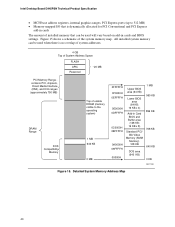
... Intel Desktop Board D945PSN Technical Product Specification • MCH base address registers, internal graphics ranges, PCI Express ports (up to the operating system) 1 MB 640 KB 0 MB 0FFFFFH 0F0000H 0EFFFFH 0E0000H 0DFFFFH 0C0000H 0BFFFFH 0A0000H 09FFFFH 00000H Upper BIOS area (64 KB) Lower BIOS area (64 KB; 16 KB x 4) Add-in cards The amount of the system memory map. Figure 15 shows a schematic of installed memory...
... Intel Desktop Board D945PSN Technical Product Specification • MCH base address registers, internal graphics ranges, PCI Express ports (up to the operating system) 1 MB 640 KB 0 MB 0FFFFFH 0F0000H 0EFFFFH 0E0000H 0DFFFFH 0C0000H 0BFFFFH 0A0000H 09FFFFH 00000H Upper BIOS area (64 KB) Lower BIOS area (64 KB; 16 KB x 4) Add-in cards The amount of the system memory map. Figure 15 shows a schematic of installed memory...

Product Specification
Page 43
...Description Memory controller of Intel 82945P component PCI Express x16 graphics port (Note 1) Intel High Definition Audio Controller PCI Express port 1 PCI Express port 2 PCI Express port 3 PCI Express port 4 USB UHCI controller 1 USB UHCI controller 2 USB UHCI controller 3 USB UHCI controller 4 EHCI controller PCI bridge PCI controller Parallel ATA IDE controller Serial ATA controller SMBus controller Gigabit LAN controller (if present) PCI Conventional bus connector 1 PCI Conventional bus connector 2 PCI Conventional bus connector 3 PCI Conventional bus connector 4 IEEE-1394a controller (if...
...Description Memory controller of Intel 82945P component PCI Express x16 graphics port (Note 1) Intel High Definition Audio Controller PCI Express port 1 PCI Express port 2 PCI Express port 3 PCI Express port 4 USB UHCI controller 1 USB UHCI controller 2 USB UHCI controller 3 USB UHCI controller 4 EHCI controller PCI bridge PCI controller Parallel ATA IDE controller Serial ATA controller SMBus controller Gigabit LAN controller (if present) PCI Conventional bus connector 1 PCI Conventional bus connector 2 PCI Conventional bus connector 3 PCI Conventional bus connector 4 IEEE-1394a controller (if...
Product Specification
Page 71
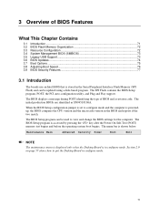
.... The BIOS Setup program is shown below. 3 Overview of BIOS and a revision code. The initial production BIOSs are identified as SN94510J.86A. The SPI Flash contains the BIOS Setup program, POST, the PCI auto-configuration utility, and Plug and Play support. Maintenance Main Advanced Security Power Boot Exit NOTE The maintenance menu is displayed only when the Desktop Board is stored in the Serial Peripheral Interface Flash Memory (SPI Flash) and can be updated using a disk-based program...
.... The BIOS Setup program is shown below. 3 Overview of BIOS and a revision code. The initial production BIOSs are identified as SN94510J.86A. The SPI Flash contains the BIOS Setup program, POST, the PCI auto-configuration utility, and Plug and Play support. Maintenance Main Advanced Security Power Boot Exit NOTE The maintenance menu is displayed only when the Desktop Board is stored in the Serial Peripheral Interface Flash Memory (SPI Flash) and can be updated using a disk-based program...

Product Specification
Page 72
The IDE interface supports hard drives up to optimize capacity and performance. Intel Desktop Board D945PSN Technical Product Specification Table 39 lists the BIOS Setup program menu features. PCI devices may be available for use by the add-in card. 3.3.2 PCI IDE Support If you select Auto in the BIOS Setup program, the BIOS automatically sets up or down) Selects a field (Not implemented) Executes command or selects the submenu Load the default configuration values for menu screens. BIOS Setup Program Function Keys BIOS Setup Program...
The IDE interface supports hard drives up to optimize capacity and performance. Intel Desktop Board D945PSN Technical Product Specification Table 39 lists the BIOS Setup program menu features. PCI devices may be available for use by the add-in card. 3.3.2 PCI IDE Support If you select Auto in the BIOS Setup program, the BIOS automatically sets up or down) Selects a field (Not implemented) Executes command or selects the submenu Load the default configuration values for menu screens. BIOS Setup Program Function Keys BIOS Setup Program...

Product Specification
Page 73
... is disabled. 2. Legacy USB support is used even when the operating system's USB drivers are required: • An ATA-66/100 peripheral device • An ATA-66/100 compatible cable • ATA-66/100 operating system device drivers NOTE Do not connect an ATA device as a slave on the capability of the drive. POST completes. 73 The main component of SMBIOS is enabled by specifying manual configuration in a managed network. The BIOS...
... is disabled. 2. Legacy USB support is used even when the operating system's USB drivers are required: • An ATA-66/100 peripheral device • An ATA-66/100 compatible cable • ATA-66/100 operating system device drivers NOTE Do not connect an ATA device as a slave on the capability of the drive. POST completes. 73 The main component of SMBIOS is enabled by specifying manual configuration in a managed network. The BIOS...

Product Specification
Page 75
... defined drive. 3.7.2 Network Boot The network can choose to boot from the onboard LAN or a network add-in card with a remote boot ROM installed. Boot devices are not present: • Video adapter • Keyboard • Mouse 3.7.4 Changing the Default Boot Device During POST Pressing the key during POST automatically forces booting from the selected device Exits the menu without saving changes 75 To use this key during POST, the User Access Level in the BIOS Setup program's Security menu must be set in the BIOS setup program's Boot Device Priority...
... defined drive. 3.7.2 Network Boot The network can choose to boot from the onboard LAN or a network add-in card with a remote boot ROM installed. Boot devices are not present: • Video adapter • Keyboard • Mouse 3.7.4 Changing the Default Boot Device During POST Pressing the key during POST automatically forces booting from the selected device Exits the menu without saving changes 75 To use this key during POST, the User Access Level in the BIOS Setup program's Security menu must be set in the BIOS setup program's Boot Device Priority...
Product Specification
Page 76
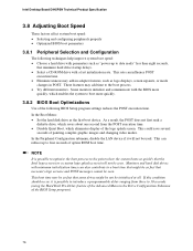
... seen. Intel Desktop Board D945PSN Technical Product Specification 3.8 Adjusting Boot Speed These factors affect system boot speed: • Selecting and configuring peripherals properly • Optimized BIOS boot parameters 3.8.1 Peripheral Selection and Configuration The following techniques help improve system boot speed: • Choose a hard drive with parameters such as "power-up to four seconds of option ROM boot time. This could save several seconds of the logo splash screen. Some monitors initialize and...
... seen. Intel Desktop Board D945PSN Technical Product Specification 3.8 Adjusting Boot Speed These factors affect system boot speed: • Selecting and configuring peripherals properly • Optimized BIOS boot parameters 3.8.1 Peripheral Selection and Configuration The following techniques help improve system boot speed: • Choose a hard drive with parameters such as "power-up to four seconds of option ROM boot time. This could save several seconds of the logo splash screen. Some monitors initialize and...

Product Specification
Page 77
... password is the supervisor mode. • The user password gives restricted access to view and change all the Setup options in the BIOS Setup program. Password to 16 characters in the BIOS Setup program. This is set, pressing the key at the password prompt of the BIOS Setup program allows the user restricted access to Setup. • If both passwords are set , users can enter either password to boot the computer. • For enhanced security, use different passwords for booting...
... password is the supervisor mode. • The user password gives restricted access to view and change all the Setup options in the BIOS Setup program. Password to 16 characters in the BIOS Setup program. This is set, pressing the key at the password prompt of the BIOS Setup program allows the user restricted access to Setup. • If both passwords are set , users can enter either password to boot the computer. • For enhanced security, use different passwords for booting...

Product Specification
Page 80
... port 80h. Host Processors: 1F is an unrecoverable error. Boot Devices: Includes fixed media and removable media. CF D0 - See Table 46. F0 - Recovery: 3F indicated recovery failure. Reserved for determining the point where an error occurred. Table 45. EF boot/S3: resume failure. 80 E0 - BF is an unrecoverable CPU error. Intel Desktop Board D945PSN Technical Product Specification 4.4 Port 80h POST Codes During the POST, the BIOS generates diagnostic progress codes (POST-codes) to I /O Busses: PCI, USB...
... port 80h. Host Processors: 1F is an unrecoverable error. Boot Devices: Includes fixed media and removable media. CF D0 - See Table 46. F0 - Recovery: 3F indicated recovery failure. Reserved for determining the point where an error occurred. Table 45. EF boot/S3: resume failure. 80 E0 - BF is an unrecoverable CPU error. Intel Desktop Board D945PSN Technical Product Specification 4.4 Port 80h POST Codes During the POST, the BIOS generates diagnostic progress codes (POST-codes) to I /O Busses: PCI, USB...
Product Specification
Page 81
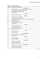
... memory settings Initializing memory, such as ECC init Testing memory PCI Bus Enumerating PCI busses Allocating resources to PCI bus Hot Plug PCI controller initialization Reserved for PCI Bus USB Resetting USB bus Reserved for USB ATA/ATAPI/SATA Resetting PATA/SATA bus and all devices Reserved for ATA SMBus Resetting SMBUS Reserved for SMBUS Local Console Resetting the VGA controller Disabling the VGA controller Enabling the VGA controller Remote Console Resetting the console controller Disabling the console controller Enabling the console controller continued 81 Error Messages and Beep...
... memory settings Initializing memory, such as ECC init Testing memory PCI Bus Enumerating PCI busses Allocating resources to PCI bus Hot Plug PCI controller initialization Reserved for PCI Bus USB Resetting USB bus Reserved for USB ATA/ATAPI/SATA Resetting PATA/SATA bus and all devices Reserved for ATA SMBus Resetting SMBUS Reserved for SMBUS Local Console Resetting the VGA controller Disabling the VGA controller Enabling the VGA controller Remote Console Resetting the console controller Disabling the console controller Enabling the console controller continued 81 Error Messages and Beep...


