
Product Specification
Page 5
Contents 1 Product Description 1.1 Overview ...10 1.1.1 Feature Summary 10 1.1.2 Manufacturing Options 11 1.1.3 Board Layout 12 1.1.4 Block Diagram 14 1.2 Online Support ...15 1.3 Processor ...15 1.4 System Memory ...16 1.4.1 Memory Configurations 17 1.5 Intel® 945P Chipset...21 1.5.1 USB ...21 1.5.2 IDE Support 22 1.5.3 Real-Time Clock, CMOS SRAM, and Battery 24 1.6 PCI Express Connectors 24 1.7 IEEE-1394a Connectors...
Contents 1 Product Description 1.1 Overview ...10 1.1.1 Feature Summary 10 1.1.2 Manufacturing Options 11 1.1.3 Board Layout 12 1.1.4 Block Diagram 14 1.2 Online Support ...15 1.3 Processor ...15 1.4 System Memory ...16 1.4.1 Memory Configurations 17 1.5 Intel® 945P Chipset...21 1.5.1 USB ...21 1.5.2 IDE Support 22 1.5.3 Real-Time Clock, CMOS SRAM, and Battery 24 1.6 PCI Express Connectors 24 1.7 IEEE-1394a Connectors...
Product Specification
Page 7
... Block Diagram 27 11. Power States and Targeted System Power 34 9. I /O Shield Dimensions 59 24. Detailed System Memory Address Map 40 16. I /O Map ...42 13. Processor Heatsink for Front Panel USB Connectors 56 20. Localized High Temperature Zones 63 Tables 1. Feature Summary ...10 2. Effects of the Standby Power Indicator LED 38...
... Block Diagram 27 11. Power States and Targeted System Power 34 9. I /O Shield Dimensions 59 24. Detailed System Memory Address Map 40 16. I /O Map ...42 13. Processor Heatsink for Front Panel USB Connectors 56 20. Localized High Temperature Zones 63 Tables 1. Feature Summary ...10 2. Effects of the Standby Power Indicator LED 38...
Product Specification
Page 8
Front Panel Audio Connector 50 19. Processor Fan Connector 51 23. ATX12V Power Connector 52 27. States for a Two-Color Power LED 55 31. States for a One-Color Power LED 55 30. ... Specifications 65 36. Port 80h POST Codes 81 47. Interrupts ...44 15. Front and Rear Chassis Fan Connectors 51 24. Front Panel Connector 54 29. Intel Desktop Board D945PSN Technical Product Specification 14. PCI Interrupt Routing Map 46 16. Supervisor and User Password Functions 77 43.
Front Panel Audio Connector 50 19. Processor Fan Connector 51 23. ATX12V Power Connector 52 27. States for a Two-Color Power LED 55 31. States for a One-Color Power LED 55 30. ... Specifications 65 36. Port 80h POST Codes 81 47. Interrupts ...44 15. Front and Rear Chassis Fan Connectors 51 24. Front Panel Connector 54 29. Intel Desktop Board D945PSN Technical Product Specification 14. PCI Interrupt Routing Map 46 16. Supervisor and User Password Functions 77 43.

Product Specification
Page 9
1 Product Description What This Chapter Contains 1.1 Overview ...10 1.2 Online Support ...15 1.3 Processor ...15 1.4 System Memory ...16 1.5 Intel® 945P Chipset...21 1.6 PCI Express Connectors 24 1.7 IEEE-1394a Connectors (Optional 24 1.8 Legacy I/O Controller 25 1.9 Audio Subsystem ...26 1.10 LAN Subsystem ...28 1.11 Hardware Management Subsystem 31 1.12 Power Management ...33 1.13 Trusted Platform Module (Optional 38 9
1 Product Description What This Chapter Contains 1.1 Overview ...10 1.2 Online Support ...15 1.3 Processor ...15 1.4 System Memory ...16 1.5 Intel® 945P Chipset...21 1.6 PCI Express Connectors 24 1.7 IEEE-1394a Connectors (Optional 24 1.8 Legacy I/O Controller 25 1.9 Audio Subsystem ...26 1.10 LAN Subsystem ...28 1.11 Hardware Management Subsystem 31 1.12 Power Management ...33 1.13 Trusted Platform Module (Optional 38 9
Product Specification
Page 10
...12.00 inches by 9.60 inches [304.80 millimeters by 243.84 millimeters]) Processor Support for a description of LAN subsystem options. Table 1. BIOS Expansion Capabilities Instantly Available PC Technology Hardware Monitor Subsystem • Intel® BIOS (resident in the SPI Flash device) • Support for Advanced... 2.3 • Support for PCI Express Revision 1.0a • Suspend to RAM support • Wake on page 11 for an Intel® Pentium® 4 processor in an LGA775 socket with UDMA 33, ATA-66/100 support • One diskette drive interface • PS/2 keyboard and mouse...
...12.00 inches by 9.60 inches [304.80 millimeters by 243.84 millimeters]) Processor Support for a description of LAN subsystem options. Table 1. BIOS Expansion Capabilities Instantly Available PC Technology Hardware Monitor Subsystem • Intel® BIOS (resident in the SPI Flash device) • Support for Advanced... 2.3 • Support for PCI Express Revision 1.0a • Suspend to RAM support • Wake on page 11 for an Intel® Pentium® 4 processor in an LGA775 socket with UDMA 33, ATA-66/100 support • One diskette drive interface • PS/2 keyboard and mouse...
Product Specification
Page 14
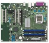
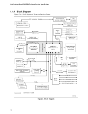
... PCI Express x1 Slot 1 PCI Express x1 Slot 2 Parallel ATA IDE Connector Parallel ATA IDE Interface LGA775 Processor Socket System Bus (1066/800/533 MHz) PCI Express x16 Interface PCI Express x16 Connector Intel 945P Chipset Intel 82945P Memory Controller Hub (MCH) Gigabit Ethernet Controller (Optional) LAN Connector USB Back Panel/Front Panel...
... PCI Express x1 Slot 1 PCI Express x1 Slot 2 Parallel ATA IDE Connector Parallel ATA IDE Interface LGA775 Processor Socket System Bus (1066/800/533 MHz) PCI Express x16 Interface PCI Express x16 Connector Intel 945P Chipset Intel 82945P Memory Controller Hub (MCH) Gigabit Ethernet Controller (Optional) LAN Connector USB Back Panel/Front Panel...
Product Specification
Page 15
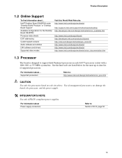
For information about ... For information about Power supply connectors Refer to support Intel Pentium 4 processors in an LGA775 processor socket with a 1066, 800, or 533 MHz system bus. See the Intel web site listed below for the Desktop Board D945PSN Processor data sheets ICH7 addressing Custom splash screens Audio software and utilities LAN software and drivers...
For information about ... For information about Power supply connectors Refer to support Intel Pentium 4 processors in an LGA775 processor socket with a 1066, 800, or 533 MHz system bus. See the Intel web site listed below for the Desktop Board D945PSN Processor data sheets ICH7 addressing Custom splash screens Audio software and utilities LAN software and drivers...
Product Specification
Page 22
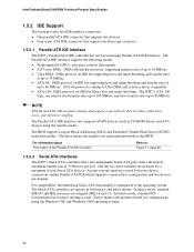
.... For information about The location of 3 Gbits/sec per channel. In legacy mode, standard IDE I /O (PIO): processor controls data transfer. • 8237-style DMA: DMA offloads the processor, supporting transfer rates of up to 16 MB/sec. • Ultra DMA: DMA protocol on IDE bus supporting host...66 and ATA-100 are assigned (IRQ 14 and 15). The ICH7's ATA-100 logic can operate in both legacy and native modes. Intel Desktop Board D945PSN Technical Product Specification 1.5.2 IDE Support The board provides five IDE interface connectors: • One parallel ATA IDE connector that ...
.... For information about The location of 3 Gbits/sec per channel. In legacy mode, standard IDE I /O (PIO): processor controls data transfer. • 8237-style DMA: DMA offloads the processor, supporting transfer rates of up to 16 MB/sec. • Ultra DMA: DMA protocol on IDE bus supporting host...66 and ATA-100 are assigned (IRQ 14 and 15). The ICH7's ATA-100 logic can operate in both legacy and native modes. Intel Desktop Board D945PSN Technical Product Specification 1.5.2 IDE Support The board provides five IDE interface connectors: • One parallel ATA IDE connector that ...

Product Specification
Page 31
... features of the hardware monitoring and fan control ASIC include: • Internal ambient temperature sensor • Two remote thermal diode sensors for direct monitoring of processor temperature and ambient temperature sensing • Power supply monitoring of the fan connectors and sensors for Management (WfM) specification. For information about The location of... Detection The board supports a chassis security feature that can be compatible with the board. The level of the fan connectors Refer to be implemented using Intel Desktop Utilities or third-party software.
... features of the hardware monitoring and fan control ASIC include: • Internal ambient temperature sensor • Two remote thermal diode sensors for direct monitoring of processor temperature and ambient temperature sensing • Power supply monitoring of the fan connectors and sensors for Management (WfM) specification. For information about The location of... Detection The board supports a chassis security feature that can be compatible with the board. The level of the fan connectors Refer to be implemented using Intel Desktop Utilities or third-party software.

Product Specification
Page 32
Thermal Sensors and Fan Connectors 32 Intel Desktop Board D945PSN Technical Product Specification 1.11.4 Thermal Monitoring Figure 13 shows the location of the sensors and fan connectors. 4 1 1 3 A B C 4 1 D 13 Item A B C D E F G G F E OM17954 Description Remote ambient temperature sensor Thermal diode, located on processor die Ambient temperature sensor, internal to hardware monitoring and fan control ASIC Processor fan Rear chassis fan Front chassis fan Auxiliary fan (optional) Figure 13.
Thermal Sensors and Fan Connectors 32 Intel Desktop Board D945PSN Technical Product Specification 1.11.4 Thermal Monitoring Figure 13 shows the location of the sensors and fan connectors. 4 1 1 3 A B C 4 1 D 13 Item A B C D E F G G F E OM17954 Description Remote ambient temperature sensor Thermal diode, located on processor die Ambient temperature sensor, internal to hardware monitoring and fan control ASIC Processor fan Rear chassis fan Front chassis fan Auxiliary fan (optional) Figure 13.
Product Specification
Page 34
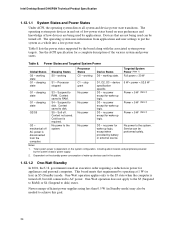
... requirement by operating at 1 W (or less) in S5 (Standby) mode. working C0 - working state S0 - working D0 - Processor stopped C1 - Context saved to the system. S5 - no power except for wake-up logic. D3 - no power except for wake...One-Watt Standby In 2001, the U.S. Power States and Targeted System Power Global States Sleeping States Processor States Device States Targeted System Power (Note 1) G0 - Suspend to RAM. No power D3 - Intel Desktop Board D945PSN Technical Product Specification 1.12.1.1 System States and Power States Under ACPI, the operating...
... requirement by operating at 1 W (or less) in S5 (Standby) mode. working C0 - working state S0 - working D0 - Processor stopped C1 - Context saved to the system. S5 - no power except for wake-up logic. D3 - no power except for wake...One-Watt Standby In 2001, the U.S. Power States and Targeted System Power Global States Sleeping States Processor States Device States Targeted System Power (Note 1) G0 - Suspend to RAM. No power D3 - Intel Desktop Board D945PSN Technical Product Specification 1.12.1.1 System States and Power States Under ACPI, the operating...
Product Specification
Page 36
..., S4, or S5 state. • Each fan connector is as needed. • All fan connectors have a +12 V DC connection. Intel Desktop Board D945PSN Technical Product Specification NOTE The use of Resume on Ring and Wake from USB technologies from an AC power failure, the computer...51 1.12.2.3 LAN Wake Capabilities CAUTION For LAN wake capabilities, the +5 V standby line for thermal monitoring The signal names of the processor fan connector The signal names of the chassis fan connectors Refer to provide adequate standby current when implementing LAN wake capabilities can be capable ...
..., S4, or S5 state. • Each fan connector is as needed. • All fan connectors have a +12 V DC connection. Intel Desktop Board D945PSN Technical Product Specification NOTE The use of Resume on Ring and Wake from USB technologies from an AC power failure, the computer...51 1.12.2.3 LAN Wake Capabilities CAUTION For LAN wake capabilities, the +5 V standby line for thermal monitoring The signal names of the processor fan connector The signal names of the chassis fan connectors Refer to provide adequate standby current when implementing LAN wake capabilities can be capable ...

Product Specification
Page 51
Processor Fan Connector Pin Signal Name 1 Ground 2 +12 V 3 FAN_TACH 4 FAN_CONTROL 2.8.2.1 Chassis Fan Connectors The board has two standard and one optional chassis fan connectors: • Front ...
Processor Fan Connector Pin Signal Name 1 Ground 2 +12 V 3 FAN_TACH 4 FAN_CONTROL 2.8.2.1 Chassis Fan Connectors The board has two standard and one optional chassis fan connectors: • Front ...

Product Specification
Page 52
... 2 connector. The 2 x 12 main power cable can provide up to do so will be used on Intel Desktop boards. Table 26. This connector provides power directly to the processor voltage regulator and must always be unconnected. Table 25. Failure to 144 W of the main power connector, ...leaving pins 11, 12, 23, and 24 unconnected. • ATX12V power - Intel Desktop Board D945PSN Technical Product Specification 2.8.2.2 ...
... 2 connector. The 2 x 12 main power cable can provide up to do so will be used on Intel Desktop boards. Table 26. This connector provides power directly to the processor voltage regulator and must always be unconnected. Table 25. Failure to 144 W of the main power connector, ...leaving pins 11, 12, 23, and 24 unconnected. • ATX12V power - Intel Desktop Board D945PSN Technical Product Specification 2.8.2.2 ...

Product Specification
Page 57
... the jumper settings for booting. Otherwise, the board could be damaged. A 1 recovery diskette is displayed. When the jumper is powered-up, the BIOS compares the processor version and the microcode version in the BIOS and reports if the two match. 31 J7J3 Figure 21. Technical Reference 2.9 Jumper Block CAUTION Do not...
... the jumper settings for booting. Otherwise, the board could be damaged. A 1 recovery diskette is displayed. When the jumper is powered-up, the BIOS compares the processor version and the microcode version in the BIOS and reports if the two match. 31 J7J3 Figure 21. Technical Reference 2.9 Jumper Block CAUTION Do not...

Product Specification
Page 60
...PCI Express x16 slot filled) must not exceed 14 A. 60 The total +5 V current draw for both boards is similar to the processor, memory, and USB ports. Minimum values assume a light load placed on the system's usage model and not necessarily tied to determine ...the overall system power requirements. Intel Desktop Board D945PSN Technical Product Specification 2.11 Electrical Considerations 2.11.1 DC Loading Table 32 lists the DC loading characteristics of +5 V current...
...PCI Express x16 slot filled) must not exceed 14 A. 60 The total +5 V current draw for both boards is similar to the processor, memory, and USB ports. Minimum values assume a light load placed on the system's usage model and not necessarily tied to determine ...the overall system power requirements. Intel Desktop Board D945PSN Technical Product Specification 2.11 Electrical Considerations 2.11.1 DC Loading Table 32 lists the DC loading characteristics of +5 V current...

Product Specification
Page 61
...and manufacturing options. System integrators should refer to a chassis fan connector. The power supply must be connected to the processor fan connector, not to the power usage values listed in the indicated sections of the ATX form factor specification. &#...; The current capability of the fan connectors. The total amount of providing adequate +5 V standby current. Table 33. Fan Connector Current Capability Fan Connector Processor fan Front chassis fan Rear chassis fan Auxiliary fan (optional) Maximum Available Current 3.0 A 1.5 A 1.5 A 3.0 A 2.11.4 Power Supply Considerations ...
...and manufacturing options. System integrators should refer to a chassis fan connector. The power supply must be connected to the processor fan connector, not to the power usage values listed in the indicated sections of the ATX form factor specification. &#...; The current capability of the fan connectors. The total amount of providing adequate +5 V standby current. Table 33. Fan Connector Current Capability Fan Connector Processor fan Front chassis fan Rear chassis fan Auxiliary fan (optional) Maximum Available Current 3.0 A 1.5 A 1.5 A 3.0 A 2.11.4 Power Supply Considerations ...

Product Specification
Page 62
... with adequate thermal performance. Failure to do so could cause components to maintain required airflow across the processor voltage regulator area. Intel Desktop Board D945PSN Technical Product Specification 2.12 Thermal Considerations CAUTION A chassis with the reader. OM16996 Figure 24.... Intel makes no warranties or representations that have been tested with Intel desktop boards please refer to the following the instructions presented in this document will result in Section 2.14. 62 Use a processor heatsink that the ambient temperature does...
... with adequate thermal performance. Failure to do so could cause components to maintain required airflow across the processor voltage regulator area. Intel Desktop Board D945PSN Technical Product Specification 2.12 Thermal Considerations CAUTION A chassis with the reader. OM16996 Figure 24.... Intel makes no warranties or representations that have been tested with Intel desktop boards please refer to the following the instructions presented in this document will result in Section 2.14. 62 Use a processor heatsink that the ambient temperature does...

Product Specification
Page 63
A B D C OM17961 Item A B C D Description Processor voltage regulator area Processor Intel 82945P MCH Intel 82801G ICH7 Figure 25. The processor voltage regulator area (item A in Figure 25) can reach a temperature of the localized high temperature zones. Technical Reference CAUTION Ensure that proper airflow is maintained in an open chassis. Failure to do so may result in damage to 85 oC in the processor voltage regulator circuit. Figure 25 shows the locations of up to the voltage regulator circuit. Localized High Temperature Zones 63
A B D C OM17961 Item A B C D Description Processor voltage regulator area Processor Intel 82945P MCH Intel 82801G ICH7 Figure 25. The processor voltage regulator area (item A in Figure 25) can reach a temperature of the localized high temperature zones. Technical Reference CAUTION Ensure that proper airflow is maintained in an open chassis. Failure to do so may result in damage to 85 oC in the processor voltage regulator circuit. Figure 25 shows the locations of up to the voltage regulator circuit. Localized High Temperature Zones 63

Product Specification
Page 64
... that are important when considering proper airflow to cool the board. Table 34. The MTBF for Components Component Intel Pentium 4 processor Intel 82945P MCH Intel 82801G ICH7 Maximum Case Temperature For processor case temperature, see processor datasheets and processor specification updates 103 oC (under bias) 110 oC (under bias, without heatsink) 99 oC (under bias, with heatsink...
... that are important when considering proper airflow to cool the board. Table 34. The MTBF for Components Component Intel Pentium 4 processor Intel 82945P MCH Intel 82801G ICH7 Maximum Case Temperature For processor case temperature, see processor datasheets and processor specification updates 103 oC (under bias) 110 oC (under bias, without heatsink) 99 oC (under bias, with heatsink...


