Product Specification
Page 6
...3.3.1 PCI* Autoconfiguration 56 3.4 System Management BIOS (SMBIOS 57 3.5 Legacy USB Support 58 3.6 BIOS Updates 59 3.6.1 Language Support 59 3.6.2 Custom Splash Screen 59 3.7 BIOS Recovery 60 3.8 Boot Options 61 3.8.1 CD-ROM Boot 61 3.8.2 Network Boot 61 3.8.3 Booting Without Attached Devices 61 3.8.4 Changing the Default Boot Device During POST 61 3.9 Adjusting Boot Speed 62 3.9.1 Peripheral Selection and Configuration 62 3.9.2 BIOS Boot Optimizations 62 3.10 BIOS Security Features 63 4 Error Messages and Beep Codes 4.1 BIOS Front-panel Power LED Codes 65 4.2 BIOS Beep Codes...
...3.3.1 PCI* Autoconfiguration 56 3.4 System Management BIOS (SMBIOS 57 3.5 Legacy USB Support 58 3.6 BIOS Updates 59 3.6.1 Language Support 59 3.6.2 Custom Splash Screen 59 3.7 BIOS Recovery 60 3.8 Boot Options 61 3.8.1 CD-ROM Boot 61 3.8.2 Network Boot 61 3.8.3 Booting Without Attached Devices 61 3.8.4 Changing the Default Boot Device During POST 61 3.9 Adjusting Boot Speed 62 3.9.1 Peripheral Selection and Configuration 62 3.9.2 BIOS Boot Optimizations 62 3.10 BIOS Security Features 63 4 Error Messages and Beep Codes 4.1 BIOS Front-panel Power LED Codes 65 4.2 BIOS Beep Codes...
Product Specification
Page 7
... Panel USB Headers 48 12. Intel Desktop Board D945GCLF2 Environmental Specifications 54 26. Rear Chassis (3-Pin) Fan Header 44 14. States for BIOS Recovery 60 vii Back Panel Connectors 41 9. Supported Memory Configurations 15 4. ATX12V Power Connector 46 18. BIOS Setup Program Function Keys 56 28. AcceptableDrives/Media Types for a One-Color Power LED 47 20. Block Diagram 13 3. Back Panel Audio Connectors 23 4. Location of the Jumper Block 49 13. Detailed System Memory Address Map 38 8. Effects of Pressing the Power Switch 28 7. Main Power...
... Panel USB Headers 48 12. Intel Desktop Board D945GCLF2 Environmental Specifications 54 26. Rear Chassis (3-Pin) Fan Header 44 14. States for BIOS Recovery 60 vii Back Panel Connectors 41 9. Supported Memory Configurations 15 4. ATX12V Power Connector 46 18. BIOS Setup Program Function Keys 56 28. AcceptableDrives/Media Types for a One-Color Power LED 47 20. Block Diagram 13 3. Back Panel Audio Connectors 23 4. Location of the Jumper Block 49 13. Detailed System Memory Address Map 38 8. Effects of Pressing the Power Switch 28 7. Main Power...

Product Specification
Page 8
Boot Device Menu Options 61 30. BIOS Error Messages 66 34. Beep Codes 66 33. EMC Regulations 79 40. Supervisor and User Password Functions 63 31. Port 80h POST Codes 68 36. Front-panel Power LED Blink Codes 65 32. Safety Standards 73 38. Port 80h POST Code Ranges 67 35. Lead-Free Board Markings 78 39. Intel Desktop Board D945GCLF2 Technical Product Specification 29. Product Certification Markings 80 viii Typical Port 80h POST Sequence 71 37.
Boot Device Menu Options 61 30. BIOS Error Messages 66 34. Beep Codes 66 33. EMC Regulations 79 40. Supervisor and User Password Functions 63 31. Port 80h POST Codes 68 36. Front-panel Power LED Blink Codes 65 32. Safety Standards 73 38. Port 80h POST Code Ranges 67 35. Lead-Free Board Markings 78 39. Intel Desktop Board D945GCLF2 Technical Product Specification 29. Product Certification Markings 80 viii Typical Port 80h POST Sequence 71 37.
Product Specification
Page 9
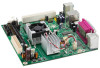
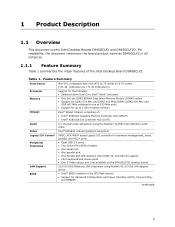
... Memory Controller Hub (GMCH) • Intel® 82801GB I/O Controller Hub (ICH7) Audio Video Legacy I/O Control Peripheral Interfaces LAN Support BIOS 5.1-channel audio subsystem using the Realtek* ALC662 high definition audio codec Intel® GMA950 onboard graphics subsystem SMSC LPC47M997 based Legacy I/O controller for hardware management, serial, parallel, and PS/2* ports • Eight USB 2.0 ports • Two Serial ATA (SATA) headers • One serial port • One parallel port • One Parallel ATA IDE interface with UDMA 33, ATA-66/100 support • PS/2 keyboard...
... Memory Controller Hub (GMCH) • Intel® 82801GB I/O Controller Hub (ICH7) Audio Video Legacy I/O Control Peripheral Interfaces LAN Support BIOS 5.1-channel audio subsystem using the Realtek* ALC662 high definition audio codec Intel® GMA950 onboard graphics subsystem SMSC LPC47M997 based Legacy I/O controller for hardware management, serial, parallel, and PS/2* ports • Eight USB 2.0 ports • Two Serial ATA (SATA) headers • One serial port • One parallel port • One Parallel ATA IDE interface with UDMA 33, ATA-66/100 support • PS/2 keyboard...
Product Specification
Page 14
... Specification 1.2 Legacy Considerations This board differs from other Intel Desktop Board products, with specific changes including (but not limited to support the Dual-Core Intel Atom processor soldered down. # INTEGRATOR'S NOTE Use only ATX12V-compliant power supplies. Intel® Desktop Board D945GCLF2 Intel Desktop Board Support Available configurations for the Intel Desktop Board D945GCLF2 Chipset information BIOS and driver updates Visit this World Wide Web site: http://www.intel.com/products/motherboard/D945GCLF2/index.htm http://support.intel.com/support/motherboards/desktop...
... Specification 1.2 Legacy Considerations This board differs from other Intel Desktop Board products, with specific changes including (but not limited to support the Dual-Core Intel Atom processor soldered down. # INTEGRATOR'S NOTE Use only ATX12V-compliant power supplies. Intel® Desktop Board D945GCLF2 Intel Desktop Board Support Available configurations for the Intel Desktop Board D945GCLF2 Chipset information BIOS and driver updates Visit this World Wide Web site: http://www.intel.com/products/motherboard/D945GCLF2/index.htm http://support.intel.com/support/motherboards/desktop...

Product Specification
Page 15
... 3 lists the supported DIMM configurations. Table 3. Product Description 1.5 System Memory The board has one row of SDRAM) and "SS" refers to : http://support.intel.com/support/motherboards/desktop/sb/ CS-025414.htm 15 This allows the BIOS to read the SPD data and program the chipset to run at 533 MHz only) NOTE To be fully compliant with all applicable DDR2 SDRAM memory specifications...
... 3 lists the supported DIMM configurations. Table 3. Product Description 1.5 System Memory The board has one row of SDRAM) and "SS" refers to : http://support.intel.com/support/motherboards/desktop/sb/ CS-025414.htm 15 This allows the BIOS to read the SPD data and program the chipset to run at 533 MHz only) NOTE To be fully compliant with all applicable DDR2 SDRAM memory specifications...
Product Specification
Page 18
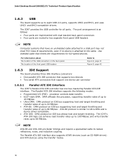
... with dual stacked back panel connectors • Four ports are faster timings and require a specialized cable to 88 MB/sec. The port arrangement is as CD-ROM drives) and ATA devices using the transfer modes. 18 ATA-66 protocol is device driver compatible. • ATA-100: DMA protocol on the back panel The location of the USB connectors on IDE bus allows host and target throttling. The ICH7 provides the USB controller...
... with dual stacked back panel connectors • Four ports are faster timings and require a specialized cable to 88 MB/sec. The port arrangement is as CD-ROM drives) and ATA devices using the transfer modes. 18 ATA-66 protocol is device driver compatible. • ATA-100: DMA protocol on the back panel The location of the USB connectors on IDE bus allows host and target throttling. The ICH7 provides the USB controller...
Product Specification
Page 24
.../1000 Mbits/sec Ethernet LAN connectivity • RJ-45 LAN connector with integrated status LEDs Additional features of the LAN subsystem include: • CSMA/CD protocol engine • LAN connect interface that supports the 82562G • PCI Conventional bus power management ⎯ Supports ACPI technology ⎯ Supports LAN wake capabilities 1.11.1 LAN Subsystem Software LAN software and drivers are available from Intel's World Wide Web site. For information about Obtaining LAN software and drivers Refer to Section...
.../1000 Mbits/sec Ethernet LAN connectivity • RJ-45 LAN connector with integrated status LEDs Additional features of the LAN subsystem include: • CSMA/CD protocol engine • LAN connect interface that supports the 82562G • PCI Conventional bus power management ⎯ Supports ACPI technology ⎯ Supports LAN wake capabilities 1.11.1 LAN Subsystem Software LAN software and drivers are available from Intel's World Wide Web site. For information about Obtaining LAN software and drivers Refer to Section...

Product Specification
Page 28
... use of individual devices, add-in boards (some add-in boards may require an ACPI-aware driver), video displays, and hard disk drives • Methods for achieving less than four seconds Sleep (ACPI G1 - Intel Desktop Board D945GCLF2 Technical Product Specification 1.13 Power Management Power management is implemented at several levels, including: • Software support through Advanced Configuration and Power Interface (ACPI) • Hardware support: ⎯ Power connector ⎯ Fan headers ⎯ LAN wake capabilities ⎯ Instantly Available PC technology ⎯ Wake from USB...
... use of individual devices, add-in boards (some add-in boards may require an ACPI-aware driver), video displays, and hard disk drives • Methods for achieving less than four seconds Sleep (ACPI G1 - Intel Desktop Board D945GCLF2 Technical Product Specification 1.13 Power Management Power management is implemented at several levels, including: • Software support through Advanced Configuration and Power Interface (ACPI) • Hardware support: ⎯ Power connector ⎯ Fan headers ⎯ LAN wake capabilities ⎯ Instantly Available PC technology ⎯ Wake from USB...
Product Specification
Page 48
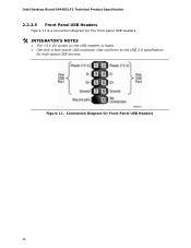
Connection Diagram for high-speed USB devices. Figure 11. Intel Desktop Board D945GCLF2 Technical Product Specification 2.2.2.5 Front Panel USB Headers Figure 11 is a connection diagram for the front panel USB headers. # INTEGRATOR'S NOTES • The +5 V DC power on the USB headers is fused. • Use only a front panel USB connector that conforms to the USB 2.0 specification for Front Panel USB Headers 48
Connection Diagram for high-speed USB devices. Figure 11. Intel Desktop Board D945GCLF2 Technical Product Specification 2.2.2.5 Front Panel USB Headers Figure 11 is a connection diagram for the front panel USB headers. # INTEGRATOR'S NOTES • The +5 V DC power on the USB headers is fused. • Use only a front panel USB connector that conforms to the USB 2.0 specification for Front Panel USB Headers 48

Product Specification
Page 55
... used to view and change the BIOS settings for the computer. The menu bar is accessed by pressing the key after the Power-On Self-Test (POST) memory test begins and before the operating system boot begins. Maintenance Main Advanced Security Power Boot Exit NOTE The maintenance menu is displayed only when the board is stored in configure mode. 3 Overview of BIOS and a revision code. The SPI Flash contains the BIOS Setup program, POST, the PCI auto-configuration utility, LAN...
... used to view and change the BIOS settings for the computer. The menu bar is accessed by pressing the key after the Power-On Self-Test (POST) memory test begins and before the operating system boot begins. Maintenance Main Advanced Security Power Boot Exit NOTE The maintenance menu is displayed only when the board is stored in configure mode. 3 Overview of BIOS and a revision code. The SPI Flash contains the BIOS Setup program, POST, the PCI auto-configuration utility, LAN...
Product Specification
Page 56
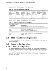
... considered to be onboard or add-in card. 56 PCI devices may be available for use by the add-in cards. Intel Desktop Board D945GCLF2 Technical Product Specification Table 26 lists the BIOS Setup program menu features. BIOS Setup Program Menu Bar Maintenance Main Advanced Security Clears passwords and displays processor information Displays processor and memory configuration Configures advanced features available through the chipset Sets passwords and security features Power Boot Configures power management features and power supply controls Selects boot options Exit Saves...
... considered to be onboard or add-in card. 56 PCI devices may be available for use by the add-in cards. Intel Desktop Board D945GCLF2 Technical Product Specification Table 26 lists the BIOS Setup program menu features. BIOS Setup Program Menu Bar Maintenance Main Advanced Security Clears passwords and displays processor information Displays processor and memory configuration Configures advanced features available through the chipset Sets passwords and security features Power Boot Configures power management features and power supply controls Selects boot options Exit Saves...
Product Specification
Page 61
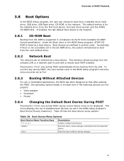
... a boot device. Boot devices are not present: • Video adapter • Keyboard • Mouse 3.8.4 Changing the Default Boot Device During POST Pressing the key during POST causes a boot device menu to boot from the onboard LAN or a network add-in the BIOS Setup program, ATAPI CDROM is supported in compliance to be the first boot device, the hard drive second, and the ATAPI CD-ROM third. Overview of available boot devices (as set to Full. 3.8.3 Booting Without Attached Devices For use this key during POST, the User Access...
... a boot device. Boot devices are not present: • Video adapter • Keyboard • Mouse 3.8.4 Changing the Default Boot Device During POST Pressing the key during POST causes a boot device menu to boot from the onboard LAN or a network add-in the BIOS Setup program, ATAPI CDROM is supported in compliance to be the first boot device, the hard drive second, and the ATAPI CD-ROM third. Overview of available boot devices (as set to Full. 3.8.3 Booting Without Attached Devices For use this key during POST, the User Access...

Product Specification
Page 62
... improve system boot speed: • Choose a hard drive with parameters such as "power-up to the boot process. • Try different monitors. Intel Desktop Board D945GCLF2 Technical Product Specification 3.9 Adjusting Boot Speed These factors affect system boot speed: • Selecting and configuring peripherals properly • Optimized BIOS boot parameters 3.9.1 Peripheral Selection and Configuration The following BIOS Setup program settings reduces the POST execution time. • In the Boot Menu, set the hard disk drive as the first boot device. This rate...
... improve system boot speed: • Choose a hard drive with parameters such as "power-up to the boot process. • Try different monitors. Intel Desktop Board D945GCLF2 Technical Product Specification 3.9 Adjusting Boot Speed These factors affect system boot speed: • Selecting and configuring peripherals properly • Optimized BIOS boot parameters 3.9.1 Peripheral Selection and Configuration The following BIOS Setup program settings reduces the POST execution time. • In the Boot Menu, set the hard disk drive as the first boot device. This rate...
Product Specification
Page 63
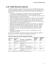
... change a Supervisor Password limited number of options User only N/A Can change all Enter Password options Clear User Password Supervisor and user set , the computer boots without asking for reference only and is entered. • Setting the user password restricts who can boot the computer. This is the user mode. • If only the supervisor password is set, pressing the key at the password prompt of the BIOS Setup program allows the user restricted access to Setup. • If both passwords are set , users...
... change a Supervisor Password limited number of options User only N/A Can change all Enter Password options Clear User Password Supervisor and user set , the computer boots without asking for reference only and is entered. • Setting the user password restricts who can boot the computer. This is the user mode. • If only the supervisor password is set, pressing the key at the password prompt of the BIOS Setup program allows the user restricted access to Setup. • If both passwords are set , users...
Product Specification
Page 65
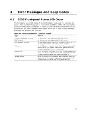
... blinks and 3-second pause) until system is complete. 4 Error Messages and Beep Codes 4.1 BIOS Front-panel Power LED Codes The front-panel power LED blinks off and on to blink an error message describing the problem (see Table 32). In addition, whenever a recoverable error occurs during POST, the BIOS causes the front-panel power LED to display messages. BIOS update in progress Video error Off when update begins, then on for 0.5 second, then off blink...
... blinks and 3-second pause) until system is complete. 4 Error Messages and Beep Codes 4.1 BIOS Front-panel Power LED Codes The front-panel power LED blinks off and on to blink an error message describing the problem (see Table 32). In addition, whenever a recoverable error occurs during POST, the BIOS causes the front-panel power LED to display messages. BIOS update in progress Video error Off when update begins, then on for 0.5 second, then off blink...
Product Specification
Page 67
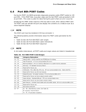
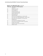
... unrecoverable CPU error. 20 - 2F Memory/Chipset: 2F is no memory detected or no useful memory detected. 30 - 3F 40 - 4F Recovery: 3F indicated recovery failure. FF: FF processor exception. 67 Port 80h POST Code Ranges Range Category/Subsystem 00 - 0F Debug codes: Can be installed in card, often called a POST card. A0 - D0 - Table 34. DF Boot device selection. Reserved for future use . 50 - 5F I /O port 80h. The POST card can decode the port and display...
... unrecoverable CPU error. 20 - 2F Memory/Chipset: 2F is no memory detected or no useful memory detected. 30 - 3F 40 - 4F Recovery: 3F indicated recovery failure. FF: FF processor exception. 67 Port 80h POST Code Ranges Range Category/Subsystem 00 - 0F Debug codes: Can be installed in card, often called a POST card. A0 - D0 - Table 34. DF Boot device selection. Reserved for future use . 50 - 5F I /O port 80h. The POST card can decode the port and display...

Product Specification
Page 69
... Enabling/configuring a fixed media Removable Media B8 Resetting removable media B9 Disabling removable media BA Detecting presence of a removable media (IDE, CD-ROM detection, etc.) BC Enabling/configuring a removable media BDS Dy Trying boot selection y (y=0 to 15) PEI Core E0 Started dispatching PEIMs (emitted on first report of EFI_SW_PC_INIT_BEGIN EFI_SW_PEI_PC_HANDOFF_TO_NEXT) E2 Permanent memory found E1, E3 Reserved for PEI/PEIMs DXE Core E4 Entered DXE phase E5 Started dispatching drivers E6 Started connecting drivers...
... Enabling/configuring a fixed media Removable Media B8 Resetting removable media B9 Disabling removable media BA Detecting presence of a removable media (IDE, CD-ROM detection, etc.) BC Enabling/configuring a removable media BDS Dy Trying boot selection y (y=0 to 15) PEI Core E0 Started dispatching PEIMs (emitted on first report of EFI_SW_PC_INIT_BEGIN EFI_SW_PEI_PC_HANDOFF_TO_NEXT) E2 Permanent memory found E1, E3 Reserved for PEI/PEIMs DXE Core E4 Entered DXE phase E5 Started dispatching drivers E6 Started connecting drivers...
Product Specification
Page 70
... password E9 Entering BIOS setup EB Calling Legacy Option ROMs Runtime Phase/EFI OS Boot F4 Entering Sleep state F5 Exiting Sleep state F8 EFI boot service ExitBootServices ( ) has been called F9 EFI runtime service SetVirtualAddressMap ( ) has been called FA EFI runtime service ResetSystem ( ) has been called PEIMs/Recovery 30 Crisis Recovery has initiated per user request 31 Crisis Recovery has initiated by software (corrupt flash) 34 Loading recovery capsule 35 Handing off control...
... password E9 Entering BIOS setup EB Calling Legacy Option ROMs Runtime Phase/EFI OS Boot F4 Entering Sleep state F5 Exiting Sleep state F8 EFI boot service ExitBootServices ( ) has been called F9 EFI runtime service SetVirtualAddressMap ( ) has been called FA EFI runtime service ResetSystem ( ) has been called PEIMs/Recovery 30 Crisis Recovery has initiated per user request 31 Crisis Recovery has initiated by software (corrupt flash) 34 Loading recovery capsule 35 Handing off control...
Product Specification
Page 71
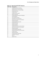
... POST Code Description 21 Initializing a chipset component 22 Reading SPD from memory DIMMs 23 Detecting presence of memory DIMMs 25 Configuring memory 28 Testing memory 34 Loading recovery capsule E4 Entered DXE phase 12 Starting application processor initialization 13 SMM initialization 50 Enumerating PCI busses 51 Allocating resourced to PCI bus 92 Detecting the presence of the keyboard 90 Resetting keyboard 94 Clearing keyboard input buffer 95 Keyboard Self Test EB Calling Video BIOS...
... POST Code Description 21 Initializing a chipset component 22 Reading SPD from memory DIMMs 23 Detecting presence of memory DIMMs 25 Configuring memory 28 Testing memory 34 Loading recovery capsule E4 Entered DXE phase 12 Starting application processor initialization 13 SMM initialization 50 Enumerating PCI busses 51 Allocating resourced to PCI bus 92 Detecting the presence of the keyboard 90 Resetting keyboard 94 Clearing keyboard input buffer 95 Keyboard Self Test EB Calling Video BIOS...


