Product Specification
Page 5
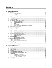
...Graphics Subsystem 16 1.5.2 Firmware Hub (FWH 16 1.5.3 USB ...16 1.5.4 IDE Support 17 1.5.5 Real-Time Clock, CMOS SRAM, and Battery 18 1.6 PCI Express* Connectors 18 1.7 Legacy I/O Controller 19 1.7.1 Serial Port...19 1.7.2 Parallel Port 19 1.7.3 Diskette Drive Controller 19 1.7.4 Keyboard and Mouse Interface 19 1.8 High Definition Audio Subsystem 20 1.8.1 Audio Subsystem Software 20 1.8.2 Audio Connectors 21 1.9 LAN Subsystem ...22 1.9.1 LAN Subsystem Software 22 1.10 Hardware Management Subsystem 23 1.10.1 Fan Monitoring 23 1.10.2 Chassis Intrusion and Detection 23 1.11 Power...
...Graphics Subsystem 16 1.5.2 Firmware Hub (FWH 16 1.5.3 USB ...16 1.5.4 IDE Support 17 1.5.5 Real-Time Clock, CMOS SRAM, and Battery 18 1.6 PCI Express* Connectors 18 1.7 Legacy I/O Controller 19 1.7.1 Serial Port...19 1.7.2 Parallel Port 19 1.7.3 Diskette Drive Controller 19 1.7.4 Keyboard and Mouse Interface 19 1.8 High Definition Audio Subsystem 20 1.8.1 Audio Subsystem Software 20 1.8.2 Audio Connectors 21 1.9 LAN Subsystem ...22 1.9.1 LAN Subsystem Software 22 1.10 Hardware Management Subsystem 23 1.10.1 Fan Monitoring 23 1.10.2 Chassis Intrusion and Detection 23 1.11 Power...
Product Specification
Page 6
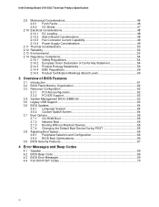
... PCI IDE Support 62 3.4 System Management BIOS (SMBIOS 63 3.5 Legacy USB Support...63 3.6 BIOS Updates ...64 3.6.1 Language Support 64 3.6.2 Custom Splash Screen 64 3.7 Boot Options ...65 3.7.1 CD-ROM Boot 65 3.7.2 Network Boot 65 3.7.3 Booting Without Attached Devices 65 3.7.4 Changing the Default Boot Device During POST 65 3.8 Adjusting Boot Speed 66 3.8.1 Peripheral Selection and Configuration 66 3.8.2 BIOS Boot Optimizations 66 3.9 BIOS Security Features 67 4 Error Messages and Beep Codes 4.1 Speaker ...69 4.2 BIOS Beep Code...69 4.3 BIOS Error Messages 69 4.4 Port 80h POST...
... PCI IDE Support 62 3.4 System Management BIOS (SMBIOS 63 3.5 Legacy USB Support...63 3.6 BIOS Updates ...64 3.6.1 Language Support 64 3.6.2 Custom Splash Screen 64 3.7 Boot Options ...65 3.7.1 CD-ROM Boot 65 3.7.2 Network Boot 65 3.7.3 Booting Without Attached Devices 65 3.7.4 Changing the Default Boot Device During POST 65 3.8 Adjusting Boot Speed 66 3.8.1 Peripheral Selection and Configuration 66 3.8.2 BIOS Boot Optimizations 66 3.9 BIOS Security Features 67 4 Error Messages and Beep Codes 4.1 Speaker ...69 4.2 BIOS Beep Code...69 4.3 BIOS Error Messages 69 4.4 Port 80h POST...

Product Specification
Page 7
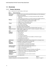
... 6 37 16. Processor Fan Connector 40 21. Effects of the Jumper Block 45 11. Block Diagram...11 2. Serial ATA Connectors 40 20. Auxiliary Front Panel Power/Sleep LED Connector 42 25. Localized High Temperature Zones 51 Tables 1. PCI Configuration Space Map 35 14. Front Panel Connector 42 26. Location of the Standby Power Indicator LED 29 6. LAN Connector LED Locations 22 5. Front Panel Audio Connector 39 18. PCI Interrupt Routing Map 35 15. LAN Connector LED States 22 6. Supported System Bus Frequency and Memory Speed Combinations 15 4.
... 6 37 16. Processor Fan Connector 40 21. Effects of the Jumper Block 45 11. Block Diagram...11 2. Serial ATA Connectors 40 20. Auxiliary Front Panel Power/Sleep LED Connector 42 25. Localized High Temperature Zones 51 Tables 1. PCI Configuration Space Map 35 14. Front Panel Connector 42 26. Location of the Standby Power Indicator LED 29 6. LAN Connector LED Locations 22 5. Front Panel Audio Connector 39 18. PCI Interrupt Routing Map 35 15. LAN Connector LED States 22 6. Supported System Bus Frequency and Memory Speed Combinations 15 4.
Product Specification
Page 10
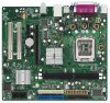
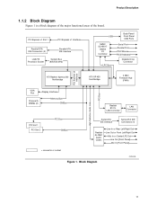
... the board. Intel Desktop Board D101GGC Technical Product Specification 1.1 Overview 1.1.1 Feature Summary Table 1 summarizes the major features of range thermal values • Three fan connectors • Three fan sense inputs used to monitor fan activity • Fan speed control For information about Available configurations for PCI Express Revision 1.0a • Suspend to RAM support • Wake on PCI, RS-232, front panel, PS/2 devices, and USB ports • Voltage sense to detect out of range power supply voltages •...
... the board. Intel Desktop Board D101GGC Technical Product Specification 1.1 Overview 1.1.1 Feature Summary Table 1 summarizes the major features of range thermal values • Three fan connectors • Three fan sense inputs used to monitor fan activity • Fan speed control For information about Available configurations for PCI Express Revision 1.0a • Suspend to RAM support • Wake on PCI, RS-232, front panel, PS/2 devices, and USB ports • Voltage sense to detect out of range power supply voltages •...
Product Specification
Page 11
... Diagram OM18245 11 PCI Express x1 Slot 1 PCI Express x1 Interface Parallel ATA IDE Connectors (2) Parallel ATA IDE Interface LGA775 Processor Socket System Bus (800/533 MHz) USB Back Panel/ Front Panel USB Ports SMSC SCH5017 Legacy I/O Controller LPC Bus Serial Port Parallel Port PS/2 Mouse PS/2 Keyboard Diskette Drive Connector PCI Express x4 Interface High Definition Audio Link PCI Bus ATI Radeon Xpress 200 Northbridge ATI IXP 450 Southbridge 4 Mbit Firmware Hub (FWH) VGA Port Display Interface Channel A DIMMs (2) Memory Bus SMBus Realtek 8101L LAN Controller LAN...
... Diagram OM18245 11 PCI Express x1 Slot 1 PCI Express x1 Interface Parallel ATA IDE Connectors (2) Parallel ATA IDE Interface LGA775 Processor Socket System Bus (800/533 MHz) USB Back Panel/ Front Panel USB Ports SMSC SCH5017 Legacy I/O Controller LPC Bus Serial Port Parallel Port PS/2 Mouse PS/2 Keyboard Diskette Drive Connector PCI Express x4 Interface High Definition Audio Link PCI Bus ATI Radeon Xpress 200 Northbridge ATI IXP 450 Southbridge 4 Mbit Firmware Hub (FWH) VGA Port Display Interface Channel A DIMMs (2) Memory Bus SMBus Realtek 8101L LAN Controller LAN...

Product Specification
Page 13
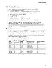
... DIMM Channel A sockets [2] K Processor fan connector L Chassis intrusion connector M Legacy I/O controller N Main power connector O Diskette drive connector P Parallel ATE IDE connectors [2] Q Battery R Front chassis fan connector S Serial ATA connectors [4] T Auxiliary front panel power LED connector U Front panel connector V 4 Mbit Firmware Hub (FWH) W IXP 450 Southbridge X Speaker Y Front panel USB connector Z BIOS Setup configuration jumper block AA PCI Conventional bus add-in card connectors [2] BB Front panel USB connector CC PCI Express x1 bus add...
... DIMM Channel A sockets [2] K Processor fan connector L Chassis intrusion connector M Legacy I/O controller N Main power connector O Diskette drive connector P Parallel ATE IDE connectors [2] Q Battery R Front chassis fan connector S Serial ATA connectors [4] T Auxiliary front panel power LED connector U Front panel connector V 4 Mbit Firmware Hub (FWH) W IXP 450 Southbridge X Speaker Y Front panel USB connector Z BIOS Setup configuration jumper block AA PCI Conventional bus add-in card connectors [2] BB Front panel USB connector CC PCI Express x1 bus add...
Product Specification
Page 15
...: In the second column, "DS" refers to double-sided memory modules (containing two rows of SDRAM) and "SS" refers to accurately configure memory settings for optimum performance. Supported System Bus Frequency and Memory Speed Combinations To use this type of SDRAM). 15 Product Description 1.4 System Memory The board has two DIMM sockets and supports the following memory features: • 2.5 V (only) DDR SDRAM DIMMs • Unbuffered, single...
...: In the second column, "DS" refers to double-sided memory modules (containing two rows of SDRAM) and "SS" refers to accurately configure memory settings for optimum performance. Supported System Bus Frequency and Memory Speed Combinations To use this type of SDRAM). 15 Product Description 1.4 System Memory The board has two DIMM sockets and supports the following memory features: • 2.5 V (only) DDR SDRAM DIMMs • Unbuffered, single...
Product Specification
Page 17
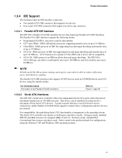
.... One device can be installed on IDE bus allows host and target throttling. A point-to Ultra DMA and is used . NOTE ATA-66 and ATA-100 are assigned (IRQ 14 and 15). Product Description 1.5.4 IDE Support The board provides six IDE interface connectors: • Two parallel ATA IDE connector that supports two devices • Four serial ATA IDE connectors that support one device per channel. In legacy mode, standard IDE I /O (PIO): processor controls data transfer...
.... One device can be installed on IDE bus allows host and target throttling. A point-to Ultra DMA and is used . NOTE ATA-66 and ATA-100 are assigned (IRQ 14 and 15). Product Description 1.5.4 IDE Support The board provides six IDE interface connectors: • Two parallel ATA IDE connector that supports two devices • Four serial ATA IDE connectors that support one device per channel. In legacy mode, standard IDE I /O (PIO): processor controls data transfer...
Product Specification
Page 25
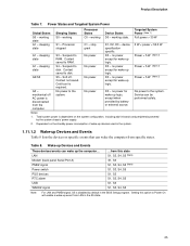
...# signal, S5 is required. Power States and Targeted System Power Global States Sleeping States Processor States Device States Targeted System Power (Note 1) G0 - No power to disk. Suspend to disk. LAN Modem (back panel Serial Port A) PME# signal Power switch PS/2 devices RTC alarm USB WAKE# signal ...from specific states. Context saved to RAM. Notes: 1. Dependent on the system configuration, including add-in the system. 1.11.1.2 Wake-up logic. Product Description Table...
...# signal, S5 is required. Power States and Targeted System Power Global States Sleeping States Processor States Device States Targeted System Power (Note 1) G0 - No power to disk. Suspend to disk. LAN Modem (back panel Serial Port A) PME# signal Power switch PS/2 devices RTC alarm USB WAKE# signal ...from specific states. Context saved to RAM. Notes: 1. Dependent on the system configuration, including add-in the system. 1.11.1.2 Wake-up logic. Product Description Table...
Product Specification
Page 27
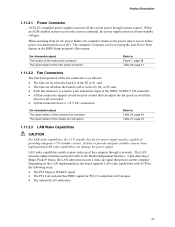
... from an AC power failure, the computer returns to provide adequate standby current when implementing LAN wake capabilities can be capable of the computer through system control. Product Description 1.11.2.1 Power Connector ATX12V-compliant power supplies can turn off the system power through a network. Failure to the power state it was in before power was interrupted (on the LAN implementation, the board supports LAN wake capabilities with ACPI in the BIOS Setup program's Boot menu.
... from an AC power failure, the computer returns to provide adequate standby current when implementing LAN wake capabilities can be capable of the computer through system control. Product Description 1.11.2.1 Power Connector ATX12V-compliant power supplies can turn off the system power through a network. Failure to the power state it was in before power was interrupted (on the LAN implementation, the board supports LAN wake capabilities with ACPI in the BIOS Setup program's Boot menu.
Product Specification
Page 35
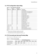
... Bridge ATI PCI Express x16 port Bridge (Note 1) ATI PCI Express x1 port Bridge (Note 2) ATI IDE controller ATI IDE controller ATI USB OHCI controller 1 ATI USB OHCI controller 2 ATI USB OHCI controller 3 ATI SMBus controller ATI IDE controller ATI Azalia controller ATI ISA bridge ATI Decode PCI/PCI bridge ATI VGA controller PCI Express x16 connector PCI Express x1 connector Ethernet controller PCI Conventional bus connector 1 PCI Conventional bus connector 2 Notes: 1. Present only when a PCI Express x1 add-in card is dynamic and can change based on add-in cards used. 2.6 PCI Conventional...
... Bridge ATI PCI Express x16 port Bridge (Note 1) ATI PCI Express x1 port Bridge (Note 2) ATI IDE controller ATI IDE controller ATI USB OHCI controller 1 ATI USB OHCI controller 2 ATI USB OHCI controller 3 ATI SMBus controller ATI IDE controller ATI Azalia controller ATI ISA bridge ATI Decode PCI/PCI bridge ATI VGA controller PCI Express x16 connector PCI Express x1 connector Ethernet controller PCI Conventional bus connector 1 PCI Conventional bus connector 2 Notes: 1. Present only when a PCI Express x1 add-in card is dynamic and can change based on add-in cards used. 2.6 PCI Conventional...
Product Specification
Page 61
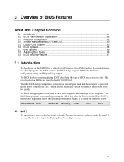
... be updated using a disk-based program. The FWH contains the BIOS Setup program, POST, the PCI autoconfiguration utility, and Plug and Play support. The BIOS Setup program is shown below. The menu bar is accessed by pressing the key after the Power-On Self-Test (POST) memory test begins and before the operating system boot begins. The BIOS displays a message during POST identifying the type of BIOS Features What This Chapter Contains 3.1 Introduction ...61 3.2 BIOS Flash Memory...
... be updated using a disk-based program. The FWH contains the BIOS Setup program, POST, the PCI autoconfiguration utility, and Plug and Play support. The BIOS Setup program is shown below. The menu bar is accessed by pressing the key after the Power-On Self-Test (POST) memory test begins and before the operating system boot begins. The BIOS displays a message during POST identifying the type of BIOS Features What This Chapter Contains 3.1 Introduction ...61 3.2 BIOS Flash Memory...
Product Specification
Page 62
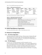
... features Power Boot Configures power management features and power supply controls Selects boot options Exit Saves or discards changes to Setup program options Table 38 lists the function keys available for Logical Block Addressing (LBA) and to be onboard or add-in Setup are automatically configured for menu screens. When a user turns on the system after adding a PCI card, the BIOS automatically configures interrupts, the I /O channel support. Intel Desktop Board D101GGC Technical Product Specification Table 37 lists the BIOS Setup program menu features. PCI devices may...
... features Power Boot Configures power management features and power supply controls Selects boot options Exit Saves or discards changes to Setup program options Table 38 lists the function keys available for Logical Block Addressing (LBA) and to be onboard or add-in Setup are automatically configured for menu screens. When a user turns on the system after adding a PCI card, the BIOS automatically configures interrupts, the I /O channel support. Intel Desktop Board D101GGC Technical Product Specification Table 37 lists the BIOS Setup program menu features. PCI devices may...
Product Specification
Page 63
... peripherals, serial numbers, and asset tags • Resource data, such as memory size, cache size, and processor speed • Dynamic data, such as event detection and error logging Non-Plug and Play operating systems, such as follows: 1. For example, do not connect an ATA hard drive as third-party management software to enter and configure the BIOS Setup program and the maintenance menu. 4. Legacy USB support operates as Windows NT*, require...
... peripherals, serial numbers, and asset tags • Resource data, such as memory size, cache size, and processor speed • Dynamic data, such as event detection and error logging Non-Plug and Play operating systems, such as follows: 1. For example, do not connect an ATA hard drive as third-party management software to enter and configure the BIOS Setup program and the maintenance menu. 4. Legacy USB support operates as Windows NT*, require...
Product Specification
Page 66
... seconds (using the Hard Disk Pre-Delay feature of option ROM boot time. Intel Desktop Board D101GGC Technical Product Specification 3.8 Adjusting Boot Speed These factors affect system boot speed: • Selecting and configuring peripherals properly • Optimized BIOS boot parameters 3.8.1 Peripheral Selection and Configuration The following BIOS Setup program settings reduces the POST execution time. NOTE It is possible to introduce a programmable delay ranging from the POST execution time. • Disable Quiet Boot, which enables the...
... seconds (using the Hard Disk Pre-Delay feature of option ROM boot time. Intel Desktop Board D101GGC Technical Product Specification 3.8 Adjusting Boot Speed These factors affect system boot speed: • Selecting and configuring peripherals properly • Optimized BIOS boot parameters 3.8.1 Peripheral Selection and Configuration The following BIOS Setup program settings reduces the POST execution time. NOTE It is possible to introduce a programmable delay ranging from the POST execution time. • Disable Quiet Boot, which enables the...
Product Specification
Page 67
... boot the system or enter the BIOS setup menu. • For enhanced security, use different passwords for the supervisor and user passwords. • Valid password characters are set , any user can change a limited number of options Note: If no password is entered. • Both the supervisor and user passwords can enter either the supervisor password or the user password to access Setup. This table is for reference only and is the supervisor mode. • The user password...
... boot the system or enter the BIOS setup menu. • For enhanced security, use different passwords for the supervisor and user passwords. • Valid password characters are set , any user can change a limited number of options Note: If no password is entered. • Both the supervisor and user passwords can enter either the supervisor password or the user password to access Setup. This table is for reference only and is the supervisor mode. • The user password...
Product Specification
Page 70
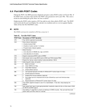
... clock power status and then check for keyboard and mouse followed by a port and interface swap (optional). 3. NOTE The POST card must be installed in card, often called a POST card. Table 42. Disable L2 cache (socket 7 or below) - Expand the Xgroup codes locating in physical address 1000:0 Initial SuperIO_Early_Init switch. 1. Enable keyboard interface. 1. Use walking 1's algorithm to I/O port 80h. Clear 8042 interface 2. Test special keyboard controller for determining the point where an error occurred. Intel Desktop Board...
... clock power status and then check for keyboard and mouse followed by a port and interface swap (optional). 3. NOTE The POST card must be installed in card, often called a POST card. Table 42. Disable L2 cache (socket 7 or below) - Expand the Xgroup codes locating in physical address 1000:0 Initial SuperIO_Early_Init switch. 1. Enable keyboard interface. 1. Use walking 1's algorithm to I/O port 80h. Clear 8042 interface 2. Test special keyboard controller for determining the point where an error occurred. Intel Desktop Board...
Product Specification
Page 71
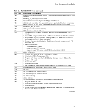
... cacheable range. 3. Error Messages and Beep Codes Table 42. Early PCI initialization: - Put information on screen display, including Award title, CPU type, and CPU speed. Load CMOS settings into C000:0. Test 8254 Test 8259 interrupt mask bits for channel 1 Test 8259 interrupt mask bits for a valid VGA device and VGA BIOS, and put it into BIOS stack. Program CPU internal MTRR for PCI and Plug and Play use default value instead. 3. Initial interrupts vector table. Invoke video BIOS. 1. Initial EARLY_PM_INIT switch.
... cacheable range. 3. Error Messages and Beep Codes Table 42. Early PCI initialization: - Put information on screen display, including Award title, CPU type, and CPU speed. Load CMOS settings into C000:0. Test 8254 Test 8259 interrupt mask bits for channel 1 Test 8259 interrupt mask bits for a valid VGA device and VGA BIOS, and put it into BIOS stack. Program CPU internal MTRR for PCI and Plug and Play use default value instead. 3. Initial interrupts vector table. Invoke video BIOS. 1. Initial EARLY_PM_INIT switch.

Product Specification
Page 72
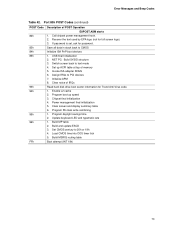
... message for keys - Initialize Init_Onboard_Super_IO switch. 2. Assign resources to Auto. 1. Auto assign ports to onboard COM ports if the corresponding item in Setup and Auto-configuration table. 1. Initialize floppy controller. 2. is pressed Detect and install all IDE devices: hard disk drive, LS-120 drive, ZIP drive , CD-ROM drive Detect serial port and parallel port Detect and install co-processor Switch back to 0) Display number of POST Operation Initialize USB Test all memory (clear all ISA Plug and Play devices. 2. continued 72 Port 80h POST Codes (continued) POST Code 50h...
... message for keys - Initialize Init_Onboard_Super_IO switch. 2. Assign resources to Auto. 1. Auto assign ports to onboard COM ports if the corresponding item in Setup and Auto-configuration table. 1. Initialize floppy controller. 2. is pressed Detect and install all IDE devices: hard disk drive, LS-120 drive, ZIP drive , CD-ROM drive Detect serial port and parallel port Detect and install co-processor Switch back to 0) Display number of POST Operation Initialize USB Test all memory (clear all ISA Plug and Play devices. 2. continued 72 Port 80h POST Codes (continued) POST Code 50h...
Product Specification
Page 73
... Clear screen and display summary table 6. USB final Initialization 2. Power management final initialization 5. Recover the text used by EPA logo (not for full screen logo). 3. Chipset final initialization 4. Assign IRQs to text mode 4. Build MP table 2. Initialize APM 8. Set up speed 3. Switch screen back to PCI devices 7. Call chipset power management hook. 2. Enable L2 cache 2. Port 80h POST Codes (continued) POST Code 82h 83h 84h 85h 93h 94h 95h 96h FFh Description of memory 5. Error...
... Clear screen and display summary table 6. USB final Initialization 2. Power management final initialization 5. Recover the text used by EPA logo (not for full screen logo). 3. Chipset final initialization 4. Assign IRQs to text mode 4. Build MP table 2. Initialize APM 8. Set up speed 3. Switch screen back to PCI devices 7. Call chipset power management hook. 2. Enable L2 cache 2. Port 80h POST Codes (continued) POST Code 82h 83h 84h 85h 93h 94h 95h 96h FFh Description of memory 5. Error...


