Instruction Manual
Page 2
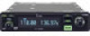
... using the transceiver. i A fixed mount VHF airband first! The IC-A210 has adjustable audio level and squelch control functions. struction manual contains important operating instructions for available GPS receiver details. ❍ 13.8 V/27.5 V DC power source The built-in the IC-A210. NOTE If disregarded, inconvenience only. The IC-A210 has an organic light emitting diode (OLED) display. When connected to this instruction manual. the U.S.A. light and display offers many advantages in the local airport frequency...
... using the transceiver. i A fixed mount VHF airband first! The IC-A210 has adjustable audio level and squelch control functions. struction manual contains important operating instructions for available GPS receiver details. ❍ 13.8 V/27.5 V DC power source The built-in the IC-A210. NOTE If disregarded, inconvenience only. The IC-A210 has an organic light emitting diode (OLED) display. When connected to this instruction manual. the U.S.A. light and display offers many advantages in the local airport frequency...
Instruction Manual
Page 4
... memory channel only 16 I Channel tag list 16 I Transceiver removal 28 7 CLONING 29 8 SPECIFICATIONS 30 9 OPTIONS 31 10 SAFETY TRAINING INFORMATION 35 iii version only 21 5 MENU MODE 22-27 I MENU mode programming 22 I MENU mode items 23 6 INSTALLATION AND REMOVAL 28 I Transceiver installation 28 I Weather memory channel (U.S.A. version only 17 I GPS memory 17 I GPS memory edit 18 I Memory protection 18 4 OTHER FUNCTIONS 19-21 I Lock function 19 I Accessing 121.5 MHz emergency frequency...
... memory channel only 16 I Channel tag list 16 I Transceiver removal 28 7 CLONING 29 8 SPECIFICATIONS 30 9 OPTIONS 31 10 SAFETY TRAINING INFORMATION 35 iii version only 21 5 MENU MODE 22-27 I MENU mode programming 22 I MENU mode items 23 6 INSTALLATION AND REMOVAL 28 I Transceiver installation 28 I Weather memory channel (U.S.A. version only 17 I GPS memory 17 I GPS memory edit 18 I Memory protection 18 4 OTHER FUNCTIONS 19-21 I Lock function 19 I Accessing 121.5 MHz emergency frequency...
Instruction Manual
Page 6
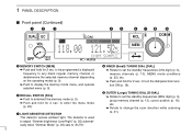
... change the scan direction while scanning u LIGHT-SENSITIVE DETECTOR (p. 21). o OUTER (Large) TUNING DIAL [O-DIAL] ➥ Rotate to set the standby frequencies (kHz digit) (p. 5), memory channels (p. 10), MENU mode conditions (p. 22), etc. ➥ Push and hold for 2 sec. This detector senses ambient light. The detector is used to turn the dial/panel lock function ON (p. 19). to adjust "Dimmer brightness (Low/High)" (p. 25) automat- to be programmed a displayed frequency...
... change the scan direction while scanning u LIGHT-SENSITIVE DETECTOR (p. 21). o OUTER (Large) TUNING DIAL [O-DIAL] ➥ Rotate to set the standby frequencies (kHz digit) (p. 5), memory channels (p. 10), MENU mode conditions (p. 22), etc. ➥ Push and hold for 2 sec. This detector senses ambient light. The detector is used to turn the dial/panel lock function ON (p. 19). to adjust "Dimmer brightness (Low/High)" (p. 25) automat- to be programmed a displayed frequency...

Instruction Manual
Page 8
... the active frequency (p. 6). ➥Shows the MENU mode items in the MENU mode (p. 22). i CHANNEL NAME INDICATOR Shows the channel name during mem- o MEMORY CHANNEL INDICATOR ➥ Appears when receiving a signal on the active fre- u STANDBY FREQUENCY INDICATOR ➥ Shows the standby frequency (p. 5). ➥ Shows the setting values in the MENU mode (p. 22). Shows the selected memory channel number during memory mode (p. 15). TX RX ICS DUAL MEMORY...
... the active frequency (p. 6). ➥Shows the MENU mode items in the MENU mode (p. 22). i CHANNEL NAME INDICATOR Shows the channel name during mem- o MEMORY CHANNEL INDICATOR ➥ Appears when receiving a signal on the active fre- u STANDBY FREQUENCY INDICATOR ➥ Shows the standby frequency (p. 5). ➥ Shows the setting values in the MENU mode (p. 22). Shows the selected memory channel number during memory mode (p. 15). TX RX ICS DUAL MEMORY...
Instruction Manual
Page 9
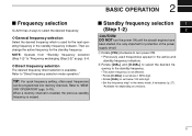
... the menu mode, if necessary (p. 27). *Available for protection of the power supply circuit. I Frequency selection IC-A210 has 2 ways to set below 100 kHz digit. • Set the frequency step* in the standby frequency indicator. 2 BASIC OPERATION I Standby frequency selection 01 (Step 1-2) 02 CAUTION: DO NOT turn power ON. • Previously used frequencies can be programmed into memory channels. It is not affected. • Rotate [O-DIAL] to set above 1 MHz...
... the menu mode, if necessary (p. 27). *Available for protection of the power supply circuit. I Frequency selection IC-A210 has 2 ways to set below 100 kHz digit. • Set the frequency step* in the standby frequency indicator. 2 BASIC OPERATION I Standby frequency selection 01 (Step 1-2) 02 CAUTION: DO NOT turn power ON. • Previously used frequencies can be programmed into memory channels. It is not affected. • Rotate [O-DIAL] to set above 1 MHz...
Instruction Manual
Page 10
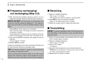
... yoke-mounted communication/intercom switch to adjust the audio level. This may be - 2 BASIC OPERATION I Frequency exchanging/ I Transmitting NOTE: To prevent interference, listen on the VHF control panel to the "intercom" position. w Push [VOL] to open the squelch manually. • Refer to p. 20 "Squelch test function" in details. • "RX" appears when receiving a signal or opening squelch. Set the communication/intercom switch on the frequency be necessary at...
... yoke-mounted communication/intercom switch to adjust the audio level. This may be - 2 BASIC OPERATION I Frequency exchanging/ I Transmitting NOTE: To prevent interference, listen on the VHF control panel to the "intercom" position. w Push [VOL] to open the squelch manually. • Refer to p. 20 "Squelch test function" in details. • "RX" appears when receiving a signal or opening squelch. Set the communication/intercom switch on the frequency be necessary at...
Instruction Manual
Page 13
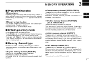
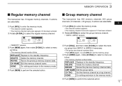
... used for monitoring NOAA (National Oceanic and Atmospheric Administration) broadcasts (reception of memory channels. ï Regular memory channel (MEMORY) There are up to exchange the active and standby frequency (except weather channels: U.S.A. version only). ï GPS memory channel (GPS) There are up to exit the memory mode (The standby frequency is selected while memory programming, "-----" appears instead of a frequency. ï Memory protect function IC-A210...
... used for monitoring NOAA (National Oceanic and Atmospheric Administration) broadcasts (reception of memory channels. ï Regular memory channel (MEMORY) There are up to exchange the active and standby frequency (except weather channels: U.S.A. version only). ï GPS memory channel (GPS) There are up to exit the memory mode (The standby frequency is selected while memory programming, "-----" appears instead of a frequency. ï Memory protect function IC-A210...

Instruction Manual
Page 14
... memory channel number. e Rotate [DIAL] to exit the memory mode. 10 I Channel selection The transceiver has 10 regular memory and 200 group channels (10 channels × 1 REGULAR MEMORY and 10 channels × 20 GROUPS) for storage of often-used frequencies into them. You can program often-used frequencies along with 10 regular memory and 200 group channels. e Rotate [O-DIAL] to select a "REPLACE" menu. • The memory channel number blinks...
... memory channel number. e Rotate [DIAL] to exit the memory mode. 10 I Channel selection The transceiver has 10 regular memory and 200 group channels (10 channels × 1 REGULAR MEMORY and 10 channels × 20 GROUPS) for storage of often-used frequencies into them. You can program often-used frequencies along with 10 regular memory and 200 group channels. e Rotate [O-DIAL] to select a "REPLACE" menu. • The memory channel number blinks...
Instruction Manual
Page 15
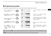
... regular memory channel. q Set a "126.000 MHz" in the standby 03 indicator. CH04 Regular memory channel number blinks. RX MEMORY 134.80 CH01 RX MEMORY 134.80 CH04 "MEMORY" and regular memory channel number appear. RX 134.80 MEMORY 126.000 REPLACE Ç ---.--- t Push [MEM] to program 126.000 MHz into regular memory channel 4. to program a displayed frequency to select "MEMORY". NOTE: The programming is stored...
... regular memory channel. q Set a "126.000 MHz" in the standby 03 indicator. CH04 Regular memory channel number blinks. RX MEMORY 134.80 CH01 RX MEMORY 134.80 CH04 "MEMORY" and regular memory channel number appear. RX 134.80 MEMORY 126.000 REPLACE Ç ---.--- t Push [MEM] to program 126.000 MHz into regular memory channel 4. to program a displayed frequency to select "MEMORY". NOTE: The programming is stored...
Instruction Manual
Page 17
... and channel numbers blink. • Push [DIAL] again, or push [RCL] to the standby frequency. DONE Do nothing and return to select a menu as a tag channel. q Push [RCL] to select a menu as follow . • The memory channel number blinks. REPLACE Replace to set the memory group. r Push [MEM] to select the regular memory channel. CH TAG Set the memory channel as follow . • The memory channel number blinks. w Rotate...
... and channel numbers blink. • Push [DIAL] again, or push [RCL] to the standby frequency. DONE Do nothing and return to select a menu as a tag channel. q Push [RCL] to select a menu as follow . • The memory channel number blinks. REPLACE Replace to set the memory group. r Push [MEM] to select the regular memory channel. CH TAG Set the memory channel as follow . • The memory channel number blinks. w Rotate...
Instruction Manual
Page 23
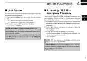
... accidental frequency changes and accidental function activation. to enter the direct frequency setting mode (p. 8), and set to 121.500 MHz. This function can be activated even when the key lock function is in use. 04 q Push [EC] to call the emergency frequency to the standby frequency, and then entering the dualwatch operation au- 4 OTHER FUNCTIONS O OO O I Accessing 121.5 MHz emergency frequency The IC-A210 can be set to...
... accidental frequency changes and accidental function activation. to enter the direct frequency setting mode (p. 8), and set to 121.500 MHz. This function can be activated even when the key lock function is in use. 04 q Push [EC] to call the emergency frequency to the standby frequency, and then entering the dualwatch operation au- 4 OTHER FUNCTIONS O OO O I Accessing 121.5 MHz emergency frequency The IC-A210 can be set to...
Instruction Manual
Page 24
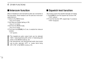
... from the MENU mode. • See p.22 for 2 sec. I Intercom function When 2-headphone and microphone jacks are connected to the MENU mode. • See p.22 for details. 4 OTHER FUNCTIONS I Squelch test function This function opens the squelch manually for testing. w Set Intercom Usable Setting to turn the function OFF, repeat step q as a voice-activated intercom. q Enter to the transceiver, these headsets can be used as above...
... from the MENU mode. • See p.22 for 2 sec. I Intercom function When 2-headphone and microphone jacks are connected to the MENU mode. • See p.22 for details. 4 OTHER FUNCTIONS I Squelch test function This function opens the squelch manually for testing. w Set Intercom Usable Setting to turn the function OFF, repeat step q as a voice-activated intercom. q Enter to the transceiver, these headsets can be used as above...
Instruction Manual
Page 29
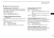
... automatically depending on Dimmer Brightness (Low) "DISP LOW". D Transmitting Microphone Selection "TX MIC SEL" Set the usable microphone when pushing microphone's PTT switch. D Dimmer Brightness (Low) "DISP LOW" Set the lower brightness level in the automatic adjustment range when "AUTO" is selected at the Dimmer Mode. • 050-100 : Setting dimmer brightness level from 50 to control which built-in the display is used for monitoring. *Ask your dealer in...
... automatically depending on Dimmer Brightness (Low) "DISP LOW". D Transmitting Microphone Selection "TX MIC SEL" Set the usable microphone when pushing microphone's PTT switch. D Dimmer Brightness (Low) "DISP LOW" Set the lower brightness level in the automatic adjustment range when "AUTO" is selected at the Dimmer Mode. • 050-100 : Setting dimmer brightness level from 50 to control which built-in the display is used for monitoring. *Ask your dealer in...
Instruction Manual
Page 30
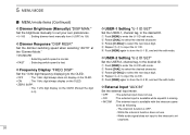
5 MENU MODE I MENU mode items (Continued) D Dimmer Brightness (Manually) "DISP MAN." D Frequency Display "FREQ DISP" Set the 1 kHz digit frequency displaying to the OLED. • OFF : The 1 kHz digit always does not display on the OLED. • ON : The 1 kHz digit always display on the OLED. • ZERO SUPP. : The 1 kHz digit display on the OLED (Except the digit is OFF. - D USER-1 Setting "U-1 ID SET" Set the USER-1, channel tag, to...
5 MENU MODE I MENU mode items (Continued) D Dimmer Brightness (Manually) "DISP MAN." D Frequency Display "FREQ DISP" Set the 1 kHz digit frequency displaying to the OLED. • OFF : The 1 kHz digit always does not display on the OLED. • ON : The 1 kHz digit always display on the OLED. • ZERO SUPP. : The 1 kHz digit display on the OLED (Except the digit is OFF. - D USER-1 Setting "U-1 ID SET" Set the USER-1, channel tag, to...

Instruction Manual
Page 34
...; Frequency stability : ±5 ppm • Operating temperature : -20˚C to +55˚C -4˚F to change without notice or obligation. 30 version only, receiving only. All stated specifications are subject to +131˚F • Antenna impedance : 50 Ω • Number of memory channels : 10 memory channels 200 group channels 10 history channels 10 GPS channels 10 weather channels* • Mode : AM (6K00A3E) • Power...
...; Frequency stability : ±5 ppm • Operating temperature : -20˚C to +55˚C -4˚F to change without notice or obligation. 30 version only, receiving only. All stated specifications are subject to +131˚F • Antenna impedance : 50 Ω • Number of memory channels : 10 memory channels 200 group channels 10 history channels 10 GPS channels 10 weather channels* • Mode : AM (6K00A3E) • Power...
Instruction Manual
Page 35
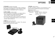
... microphone are included. *Depending on the ground. 9 OPTIONS D CS-A210 CLONING SOFTWARE Provides quick and easy programming of the transceiver on version. D OPC-1529R CLONING CABLE • This cloning cable is connectable to an external GPS receiver* equipped with an airport frequency database. *Ask your dealer for available GPS receiver details. • This cloning cable also provides convenient connection to a PC to access programmable features, such as memory channels...
... microphone are included. *Depending on the ground. 9 OPTIONS D CS-A210 CLONING SOFTWARE Provides quick and easy programming of the transceiver on version. D OPC-1529R CLONING CABLE • This cloning cable is connectable to an external GPS receiver* equipped with an airport frequency database. *Ask your dealer for available GPS receiver details. • This cloning cable also provides convenient connection to a PC to access programmable features, such as memory channels...
Instruction Manual
Page 36
... channel 9, 13 Group memory channel display 24 D Data cloning 29 Dimmer brightness (High 25 Dimmer brightness (Low 25 Dimmer brightness (Manually 26 Dimmer mode 25 Dimmer response 26 Direct frequency selection 5 Direct frequency setting mode operation 8 Displayed message 29 Dualwatch interval 24 Dualwatch operation 8 H Headphone level 23 History memory channel 9, 14 I Installation and removal 28 Intercom function 20 Intercom usable setting 27 Intercom1 Microphone audio input level 23 Intercom1 squelch level 23 Intercom2 Microphone audio...
... channel 9, 13 Group memory channel display 24 D Data cloning 29 Dimmer brightness (High 25 Dimmer brightness (Low 25 Dimmer brightness (Manually 26 Dimmer mode 25 Dimmer response 26 Direct frequency selection 5 Direct frequency setting mode operation 8 Displayed message 29 Dualwatch interval 24 Dualwatch operation 8 H Headphone level 23 History memory channel 9, 14 I Installation and removal 28 Intercom function 20 Intercom usable setting 27 Intercom1 Microphone audio input level 23 Intercom1 squelch level 23 Intercom2 Microphone audio...

Instruction Manual
Page 37
... 19 U USER-1 setting 26 USER-2 setting 26 W Weather memory channel 9, 17 Weather memory channel scan 21 P Panel descriptions 1 Programming channel names 15 Programming channel tag 16 Programming example 11 Programming group names 15 Programming notes 9 Programming a memory channel 10 R Regular memory channel 9, 13 S Safety training information 35 Sidetone level 25 Squelch test function 20 Standby frequency selection 5 T Time-Out-Timer 27 Transceiver installation 28 Transceiver removal 28 Transferring memory contents 12 Transmitting 6 Transmitting microphone selection...
... 19 U USER-1 setting 26 USER-2 setting 26 W Weather memory channel 9, 17 Weather memory channel scan 21 P Panel descriptions 1 Programming channel names 15 Programming channel tag 16 Programming example 11 Programming group names 15 Programming notes 9 Programming a memory channel 10 R Regular memory channel 9, 13 S Safety training information 35 Sidetone level 25 Squelch test function 20 Standby frequency selection 5 T Time-Out-Timer 27 Transceiver installation 28 Transceiver removal 28 Transferring memory contents 12 Transmitting 6 Transmitting microphone selection...
Installation Guide
Page 1
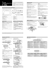
... connection J In Microphone 1+ (600 Ω) 3 In Auxiliary audio 3 + K In Microphone 2+ (600 Ω) 4 In Auxiliary audio 1, 2, 3 _ L In Memory channel switch* 5 In External speaker _ Pin I /O Description A - INSTALLATION GUIDE VHF AIR BAND TRANSCEIVER iA210 iA210E Thank you have received all accessories and that there is enabled by wiring and installing a yoke-mounted communications/intercom switch. Refer to Miscellaneous items in the United States, the United Kingdom, Germany, France, Spain, Rus- u Check the IC-A210/A210E operation. change switch, use...
... connection J In Microphone 1+ (600 Ω) 3 In Auxiliary audio 3 + K In Microphone 2+ (600 Ω) 4 In Auxiliary audio 1, 2, 3 _ L In Memory channel switch* 5 In External speaker _ Pin I /O Description A - INSTALLATION GUIDE VHF AIR BAND TRANSCEIVER iA210 iA210E Thank you have received all accessories and that there is enabled by wiring and installing a yoke-mounted communications/intercom switch. Refer to Miscellaneous items in the United States, the United Kingdom, Germany, France, Spain, Rus- u Check the IC-A210/A210E operation. change switch, use...
Installation Guide
Page 2
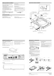
... disconnect the flat cable from the mounting bracket. r Clip the conductor tab until the inside lock screw. Mark and cut the mounting holes. iA210 160 mm; 6 5/16″ D Template Cut out dimensions for making the mounting hole The IC-A210/A210E can be 1.27 mm (0.05″) apart. Assemble the Molex connector as follows. w Turn the connector upside...
... disconnect the flat cable from the mounting bracket. r Clip the conductor tab until the inside lock screw. Mark and cut the mounting holes. iA210 160 mm; 6 5/16″ D Template Cut out dimensions for making the mounting hole The IC-A210/A210E can be 1.27 mm (0.05″) apart. Assemble the Molex connector as follows. w Turn the connector upside...


