Service Manual
Page 1
MODEL: T560 (6656-HW2) T560 (6656-HG2) COLOR MONITOR SERVICE MANUAL CAUTION BEFORE SERVICING THE UNIT, READ THE SAFETY PRECAUTIONS IN THIS MANUAL.
MODEL: T560 (6656-HW2) T560 (6656-HG2) COLOR MONITOR SERVICE MANUAL CAUTION BEFORE SERVICING THE UNIT, READ THE SAFETY PRECAUTIONS IN THIS MANUAL.

Service Manual
Page 2
...; POWER SUPPLY 4-1. SPECIFICATIONS 2 PRECAUTIONS 5 TIMING CHART 6 OPERATING INSTRUCTIONS 7 WIRING DIAGRAM 8 DISASSEMBLY 9 BLOCK DIAGRAM 11 DESCRIPTION OF BLOCK DIAGRAM 12 ADJUSTMENT 13 TROUBLESHOOTING GUIDE 14 PRINTED CIRCUIT BOARD 18 EXPLODED VIEW 20 EXPLODED VIEW PARTS LIST 21 REPLACEMENT PARTS LIST 23 PIN CONFIGURATION 27 SCHEMATIC DIAGRAM 28 SPECIFICATIONS 1. Operating Frequency Horizontal : 31 ~ 61 kHz Vertical : 56 ~ 75 Hz 5. Power Consumption MODE H/V SYNC VIDEO POWER CONSUMPTION LED COLOR POWER ON (NORMAL) ON/ON ACTIVE less than 30 W GREEN STAND...
...; POWER SUPPLY 4-1. SPECIFICATIONS 2 PRECAUTIONS 5 TIMING CHART 6 OPERATING INSTRUCTIONS 7 WIRING DIAGRAM 8 DISASSEMBLY 9 BLOCK DIAGRAM 11 DESCRIPTION OF BLOCK DIAGRAM 12 ADJUSTMENT 13 TROUBLESHOOTING GUIDE 14 PRINTED CIRCUIT BOARD 18 EXPLODED VIEW 20 EXPLODED VIEW PARTS LIST 21 REPLACEMENT PARTS LIST 23 PIN CONFIGURATION 27 SCHEMATIC DIAGRAM 28 SPECIFICATIONS 1. Operating Frequency Horizontal : 31 ~ 61 kHz Vertical : 56 ~ 75 Hz 5. Power Consumption MODE H/V SYNC VIDEO POWER CONSUMPTION LED COLOR POWER ON (NORMAL) ON/ON ACTIVE less than 30 W GREEN STAND...
Service Manual
Page 3
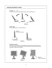
Adjusting the Monitor Position Tilt Range : -37° ~ 145° You can tilt the screen backward and forward as shown below(Figure A). -37 +145 (Figure A) Height Range You can adjust height of the screen(Figure B). The monitor rotates from Landscape to Portrait through 90°anti-clockwise. (Figure C) -3- Maximum: 4.87 inch(123.8 mm) (Figure B) Landscape & Portrait This monitor offers the ability to Landscape through 90°clockwise and from Portrait to rotate between landscape and portrait modes(Figure C). Maximum: 3.863 inch(98.1mm)
Adjusting the Monitor Position Tilt Range : -37° ~ 145° You can tilt the screen backward and forward as shown below(Figure A). -37 +145 (Figure A) Height Range You can adjust height of the screen(Figure B). The monitor rotates from Landscape to Portrait through 90°anti-clockwise. (Figure C) -3- Maximum: 4.87 inch(123.8 mm) (Figure B) Landscape & Portrait This monitor offers the ability to Landscape through 90°clockwise and from Portrait to rotate between landscape and portrait modes(Figure C). Maximum: 3.863 inch(98.1mm)
Service Manual
Page 4
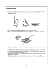
... want to keep the arm folded.) 5. To obtain the correct cables and/or to the monitor. VESA Wall Mounting Alternative mounting options for your dealer, retailer, or other IBM authorized Servicer. -4- Locate a place to which you selected in the step 6, and then reconnect the signal cable and the power cord to get further instructions on the bottom of the stand to attach the monitor to the...
... want to keep the arm folded.) 5. To obtain the correct cables and/or to the monitor. VESA Wall Mounting Alternative mounting options for your dealer, retailer, or other IBM authorized Servicer. -4- Locate a place to which you selected in the step 6, and then reconnect the signal cable and the power cord to get further instructions on the bottom of the stand to attach the monitor to the...
Service Manual
Page 5
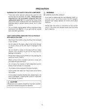
... design without obtaining written permission from shock hazard during service operation. -5- These parts are pressed cause short and may damage the panel.) CAUTION Please use only a plastic screwdriver to protect yourself from IBM Inc. TAKE CARE DURING HANDLING THE LCD MODULE WITH BACKLIGHT UNIT. • Must mount the module using mounting holes arranged in areas of the frame strongly or...
... design without obtaining written permission from shock hazard during service operation. -5- These parts are pressed cause short and may damage the panel.) CAUTION Please use only a plastic screwdriver to protect yourself from IBM Inc. TAKE CARE DURING HANDLING THE LCD MODULE WITH BACKLIGHT UNIT. • Must mount the module using mounting holes arranged in areas of the frame strongly or...
Service Manual
Page 7
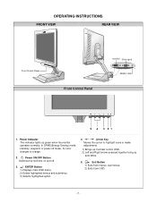
... from OSD. -7- In DPMS(Energy Saving) mode, - its color changes to highlight icons or make adjustments. 1) Brings up Contrast control OSD. 2) Left and Right arrows pressed together bring up green when the monitor operates normally; ENTER Button 1) Displays main OSD menu. 2) Enters highlighted menus and submenus. 3) Selects highlighted option. 4. OPERATING INSTRUCTIONS FRONT VIEW REAR VIEW Front Control Panel Front Control Panel DVI Port DSub signal Adapter Jack 5 4 3 21 1. Power Indicator This indicator lights up auto setup. 5. Power ON/OFF Button Switches the monitors on...
... from OSD. -7- In DPMS(Energy Saving) mode, - its color changes to highlight icons or make adjustments. 1) Brings up Contrast control OSD. 2) Left and Right arrows pressed together bring up green when the monitor operates normally; ENTER Button 1) Displays main OSD menu. 2) Enters highlighted menus and submenus. 3) Selects highlighted option. 4. OPERATING INSTRUCTIONS FRONT VIEW REAR VIEW Front Control Panel Front Control Panel DVI Port DSub signal Adapter Jack 5 4 3 21 1. Power Indicator This indicator lights up auto setup. 5. Power ON/OFF Button Switches the monitors on...

Service Manual
Page 8
WIRING DIAGRAM J1 Module link Cable : 6631T11012M P704 P703 Inverter Cable : 6631T11012L -8-
WIRING DIAGRAM J1 Module link Cable : 6631T11012M P704 P703 Inverter Cable : 6631T11012L -8-

Service Manual
Page 9
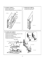
... Link Cable connector. (6) Remove the screw (b). (7) Remove the Tilt Swivel. CABINET ASS'Y REMOVAL (1) Remove four Screws (a). (2) Remove the Control PCB connerctor. (3) Remove the Cabinet Ass'y. (a) (b) Back Cover Cabinet (a) (b) (a) (b) (a) (b) (a) (a) Control PCB Connector (a) (a) -9- BACK COVER REMOVAL (1) Remove four Screw Covers (a). (2) Remove four screws (b). (3) Remove the Back Cover Ass'y. 3. Cover Hinge Module Link Cabel (b) (c) (a) (a) 2. TILT SWIVEL REMOVAL (1) Remove the Cover Hinge. (2) Remove two screws (a). (3) Remove the Cover Piece Back. (4) Remove two...
... Link Cable connector. (6) Remove the screw (b). (7) Remove the Tilt Swivel. CABINET ASS'Y REMOVAL (1) Remove four Screws (a). (2) Remove the Control PCB connerctor. (3) Remove the Cabinet Ass'y. (a) (b) Back Cover Cabinet (a) (b) (a) (b) (a) (b) (a) (a) Control PCB Connector (a) (a) -9- BACK COVER REMOVAL (1) Remove four Screw Covers (a). (2) Remove four screws (b). (3) Remove the Back Cover Ass'y. 3. Cover Hinge Module Link Cabel (b) (c) (a) (a) 2. TILT SWIVEL REMOVAL (1) Remove the Cover Hinge. (2) Remove two screws (a). (3) Remove the Cover Piece Back. (4) Remove two...
Service Manual
Page 10
... 6. TILT SWIVEL ASS'Y REMOVAL (1) Remove the Cover Hnge (a). (3) Remove the Cover Stand Body. (Change the Cable) (2) Remove the Cover Stand Rear(b). (4) Remove two screws(c). (5) Remove the Cover Stand Top. (6) Remove five screws (d) and Metal Shield Main. (7) Remove two screwS (e). (c) (c) Cover Stand Top (b) (d) (d) (d) (d) (d) Metal Shield Main (e) (e) Inverter Ass'y Remove the Cover Stand Body Cover Stand Body (a) Cover Hinge - 10 - LCD MODULE REMOVAL (1) Remove Inverter Connector. (2) Remove eight Screws (a). (3) Remove the Metal Frame from the LCD MODULE. (a) LCD...
... 6. TILT SWIVEL ASS'Y REMOVAL (1) Remove the Cover Hnge (a). (3) Remove the Cover Stand Body. (Change the Cable) (2) Remove the Cover Stand Rear(b). (4) Remove two screws(c). (5) Remove the Cover Stand Top. (6) Remove five screws (d) and Metal Shield Main. (7) Remove two screwS (e). (c) (c) Cover Stand Top (b) (d) (d) (d) (d) (d) Metal Shield Main (e) (e) Inverter Ass'y Remove the Cover Stand Body Cover Stand Body (a) Cover Hinge - 10 - LCD MODULE REMOVAL (1) Remove Inverter Connector. (2) Remove eight Screws (a). (3) Remove the Metal Frame from the LCD MODULE. (a) LCD...
Service Manual
Page 12
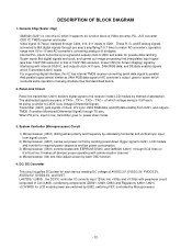
... digital. These R, G, and B analog signals converted to 8bit digital signals through C204, 210, 211 inputs to the receiver inside LCD module by each OSD function. 4. Transmitter (U401) gets signals of clock, H/V sync, 24bit RGB data, and DE(data enable) from signal source. 2) Microprocessor (U501) carries out power control by interfacing with communication channel. 4) Microprocessor (U4) lets User adjust screen by method of TX0+-, TX1+-, TX2+-, TXC+- It makes all...
... digital. These R, G, and B analog signals converted to 8bit digital signals through C204, 210, 211 inputs to the receiver inside LCD module by each OSD function. 4. Transmitter (U401) gets signals of clock, H/V sync, 24bit RGB data, and DE(data enable) from signal source. 2) Microprocessor (U501) carries out power control by interfacing with communication channel. 4) Microprocessor (U4) lets User adjust screen by method of TX0+-, TX1+-, TX2+-, TXC+- It makes all...
Service Manual
Page 13
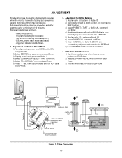
... with each mode data saved. - Programmable Signal Generator. (eg. Adjustment for White Balance 1) Display color 0,0 pattern at Mode 13. 2) Set External Bright to MAX position and Contrast to MAX Position. 3) Select PRESET START → BIAS CAL command and Enter. 4) No attempt to manually adjust, BIAS data is some probelm on the IBM compatible PC. 2) Select EEPROM all FOS data to EEPROM. 2. Control Line IBM Compatible PC 15 10 5 PARALLEL PORT Not used RS232C PARALLEL...
... with each mode data saved. - Programmable Signal Generator. (eg. Adjustment for White Balance 1) Display color 0,0 pattern at Mode 13. 2) Set External Bright to MAX position and Contrast to MAX Position. 3) Select PRESET START → BIAS CAL command and Enter. 4) No attempt to manually adjust, BIAS data is some probelm on the IBM compatible PC. 2) Select EEPROM all FOS data to EEPROM. 2. Control Line IBM Compatible PC 15 10 5 PARALLEL PORT Not used RS232C PARALLEL...
Service Manual
Page 14
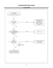
YES CHECK U803 PIN 2, 3 NO WAVEFROM? 200kHz 12V YES 40% duty CHECK KEY CONTROL CONNECTOR ROUTINE CHECK ADAPTER, AND FIND OUT SHORT POINT OF EACH DC LINE OF 2.5V AND 3.3V CHECK X501. YES CHECK X501'S WAVEFROM NO OSCILLATE AS 24MHZ ? TROUBLESHOOTING GUIDE 1. NO POWER NO POWER (POWER INDICATOR OFF) CHECK J801'S NO VOLTAGE (12V) ? CHECK U803 AND L805'S OPEN - 14 -
YES CHECK U803 PIN 2, 3 NO WAVEFROM? 200kHz 12V YES 40% duty CHECK KEY CONTROL CONNECTOR ROUTINE CHECK ADAPTER, AND FIND OUT SHORT POINT OF EACH DC LINE OF 2.5V AND 3.3V CHECK X501. YES CHECK X501'S WAVEFROM NO OSCILLATE AS 24MHZ ? TROUBLESHOOTING GUIDE 1. NO POWER NO POWER (POWER INDICATOR OFF) CHECK J801'S NO VOLTAGE (12V) ? CHECK U803 AND L805'S OPEN - 14 -
Service Manual
Page 15
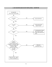
2. CAN YOU SEE PULSE AT YOUR SCOPE? YES REPLACE CCFL LAMP IN THE LCD MODULE NO - 15 - REPLACE INVERTER ASS'Y INVERTER NO RASTER (OSD IS NOT DISPLAYED) J703 PIN10 12V? YES NO CHECK ADAPTER NO CHECK MICOM INV ON/OFF PORT. 1. CHECK MICOM DIM-ADJ PORT CHECK PULSE AS CONTACTING SCOPE PROBE TO CAUTION LABEL. (CONTACT PROBE TO CAUTION LABEL. NO RASTER (OSD IS NOT DISPLAYED) - YES J703 PIN1 5V? YES J703 PIN5 5V? CONFIRM BRIGHTNESS NO OSD CONTRL STATE. 2.
2. CAN YOU SEE PULSE AT YOUR SCOPE? YES REPLACE CCFL LAMP IN THE LCD MODULE NO - 15 - REPLACE INVERTER ASS'Y INVERTER NO RASTER (OSD IS NOT DISPLAYED) J703 PIN10 12V? YES NO CHECK ADAPTER NO CHECK MICOM INV ON/OFF PORT. 1. CHECK MICOM DIM-ADJ PORT CHECK PULSE AS CONTACTING SCOPE PROBE TO CAUTION LABEL. (CONTACT PROBE TO CAUTION LABEL. NO RASTER (OSD IS NOT DISPLAYED) - YES J703 PIN1 5V? YES J703 PIN5 5V? CONFIRM BRIGHTNESS NO OSD CONTRL STATE. 2.
Service Manual
Page 16
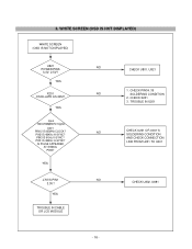
PIN1 IS 48KHz H-SYNC? IS PULSE APPEARED AT SIGNAL PINS? CHECK X201 3. WHITE SCREEN (OSD IS NOT DISPLAYED) WHITE SCREEN (OSD IS NOT DISPLAYED) U821 POWER PINS 3.3V, 2.5V? PIN2 IS 48KHz H-SYNC? YES Input 1024x768@60Hz Signal. TROUBLE IN U201 NO CHECK U201 OR U401'S SOLDERING CONDITION AND CHECK CONNECTION LINE FROM U201 TO U401 NO CHECK U802, U881 - 16 - 3. CHECK PIN34, 35 NO SOLDERING CONDITION 2. YES X201 OSCILLATE AS 24M? PIN3 IS 60Hz V-SYNC? YES TROUBLE IN CABLE OR LCD MODULE NO CHECK U801, U821 1. U401 PIN12 IS 65MHz CLOCK? YES J703'S PIN1 3.3V?
PIN1 IS 48KHz H-SYNC? IS PULSE APPEARED AT SIGNAL PINS? CHECK X201 3. WHITE SCREEN (OSD IS NOT DISPLAYED) WHITE SCREEN (OSD IS NOT DISPLAYED) U821 POWER PINS 3.3V, 2.5V? PIN2 IS 48KHz H-SYNC? YES Input 1024x768@60Hz Signal. TROUBLE IN U201 NO CHECK U201 OR U401'S SOLDERING CONDITION AND CHECK CONNECTION LINE FROM U201 TO U401 NO CHECK U802, U881 - 16 - 3. CHECK PIN34, 35 NO SOLDERING CONDITION 2. YES X201 OSCILLATE AS 24M? PIN3 IS 60Hz V-SYNC? YES TROUBLE IN CABLE OR LCD MODULE NO CHECK U801, U821 1. U401 PIN12 IS 65MHz CLOCK? YES J703'S PIN1 3.3V?
Service Manual
Page 17
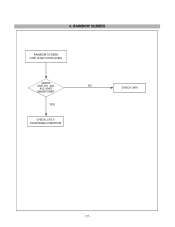
YES CHECK J703'S SOLDERING CONDITION CHECK U401 - 17 - 4. RAINBOW SCREEN RAINBOW SCREEN (OSD IS NOT DISPLAYED) CHECK CMF 401, 402, NO 403, 404'S WAVEFORM?
YES CHECK J703'S SOLDERING CONDITION CHECK U401 - 17 - 4. RAINBOW SCREEN RAINBOW SCREEN (OSD IS NOT DISPLAYED) CHECK CMF 401, 402, NO 403, 404'S WAVEFORM?
Service Manual
Page 21
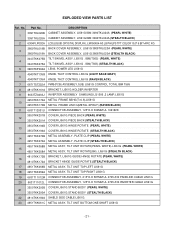
... WHITE) 15 4951TKK058A METAL ASSY, TILT UNIT ROTATE(BK). DESCRIPTION 3091TKL026B CABINET ASSEMBLY, LI561G IBM 3090TKL024A (PEARL WHITE) 1 3091TKL026A CABINET ASSEMBLY, LI561G IBM 3090TKL024A (STEALTH BLACK) 2 6304FLP002A LCD(LIQUID CRYSTAL DISPLAY), LM150X04-A3 LG PHILPS TFT COLOR 15.0" 6 BIT+FRC XG 3809TKL018B BACK COVER ASSEMBLY, LI561G 3808TKL020A (PEARL WHITE) 3 3809TKL018A BACK COVER ASSEMBLY, LI561G 3808TKL020A (STEALTH BLACK) 3043TKK075B TILT SWIVEL ASSY, LI561G . EXPLODED VIEW PARTS LIST Ref. Part No. LI561G (STEALTH BLACK) 4810TKK172B BRACKET, LI561G GUIDE...
... WHITE) 15 4951TKK058A METAL ASSY, TILT UNIT ROTATE(BK). DESCRIPTION 3091TKL026B CABINET ASSEMBLY, LI561G IBM 3090TKL024A (PEARL WHITE) 1 3091TKL026A CABINET ASSEMBLY, LI561G IBM 3090TKL024A (STEALTH BLACK) 2 6304FLP002A LCD(LIQUID CRYSTAL DISPLAY), LM150X04-A3 LG PHILPS TFT COLOR 15.0" 6 BIT+FRC XG 3809TKL018B BACK COVER ASSEMBLY, LI561G 3808TKL020A (PEARL WHITE) 3 3809TKL018A BACK COVER ASSEMBLY, LI561G 3808TKL020A (STEALTH BLACK) 3043TKK075B TILT SWIVEL ASSY, LI561G . EXPLODED VIEW PARTS LIST Ref. Part No. LI561G (STEALTH BLACK) 4810TKK172B BRACKET, LI561G GUIDE...
Service Manual
Page 22
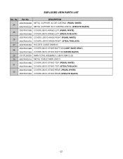
... 4950TKK322A METAL SUPPORT AL D CASTING LI561G (STEALTH BLACK) 3550TKK196B COVER LI561G HINGE LEFT (PEARL WHITE) 25 3550TKK196A COVER LI561G HINGE LEFT (STEALTH BLACK) 3550TKK197B COVER, LI561G HINGE RIGHT (PEARL WHITE) 26 3550TKK197A COVER, LI561G HINGE RIGHT (STEALTH BLACK) 27 4930TKK035A HOLDER, CABLE DAMB-05 3550TKK199B COVER LI561G STAND BOTTOM (LIGHT SAGE GRAY) 28 3550TKK199A COVER LI561G STAND BOTTOM (RAVEN BLACK) 29 3313TL5032A MAIN TOTAL ASSEMBLY, LI561G IBM CL-25...
... 4950TKK322A METAL SUPPORT AL D CASTING LI561G (STEALTH BLACK) 3550TKK196B COVER LI561G HINGE LEFT (PEARL WHITE) 25 3550TKK196A COVER LI561G HINGE LEFT (STEALTH BLACK) 3550TKK197B COVER, LI561G HINGE RIGHT (PEARL WHITE) 26 3550TKK197A COVER, LI561G HINGE RIGHT (STEALTH BLACK) 27 4930TKK035A HOLDER, CABLE DAMB-05 3550TKK199B COVER LI561G STAND BOTTOM (LIGHT SAGE GRAY) 28 3550TKK199A COVER LI561G STAND BOTTOM (RAVEN BLACK) 29 3313TL5032A MAIN TOTAL ASSEMBLY, LI561G IBM CL-25...

Service Manual
Page 23
...R/TP NP0 15PF 1608 50V 5% R/TP NP0 220PF 1608 50V 5% R/TP NP0 MODEL: T560(6656-HW2)/ T560(6656-HG2) DATE: 2001. 8. 17. *S *AL LOC. NO. PART NO. NO. PART NO. DESCRIPTION / SPECIFICATION C272 C274 C275 C276 C277 C278 C280 C281 C282 C284 C285 C286 C287 C288 C289 C290... R/TP NP0 1000PF 1608 50V 5% R/TP NP0 0.1UF 1608 50V 10% R/TP X7R - 23 - REPLACEMENT PARTS LIST CAUTION: BEFORE REPLACING ANY OF THESE COMPONENTS, READ CAREFULLY THE SAFETY PRECAUTIONS IN THIS MANUAL. * NOTE : S SAFETY Mark AL ALTERNATIVE PARTS MODEL: T560(6656-HW2)/ T560(6656-HG2) DATE: 2001. 8. 17. *S *AL LOC.
...R/TP NP0 15PF 1608 50V 5% R/TP NP0 220PF 1608 50V 5% R/TP NP0 MODEL: T560(6656-HW2)/ T560(6656-HG2) DATE: 2001. 8. 17. *S *AL LOC. NO. PART NO. NO. PART NO. DESCRIPTION / SPECIFICATION C272 C274 C275 C276 C277 C278 C280 C281 C282 C284 C285 C286 C287 C288 C289 C290... R/TP NP0 1000PF 1608 50V 5% R/TP NP0 0.1UF 1608 50V 10% R/TP X7R - 23 - REPLACEMENT PARTS LIST CAUTION: BEFORE REPLACING ANY OF THESE COMPONENTS, READ CAREFULLY THE SAFETY PRECAUTIONS IN THIS MANUAL. * NOTE : S SAFETY Mark AL ALTERNATIVE PARTS MODEL: T560(6656-HW2)/ T560(6656-HG2) DATE: 2001. 8. 17. *S *AL LOC.
Service Manual
Page 27
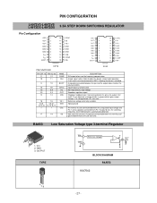
... 13 16 4,5,6 13,14,15 1 18 4,5,6,7 14,15,16,17 1 17 19 NAME COMP INH BOOT SYNC Vcc OUT VFB V5.1 GND OSC SS DESCRIPTION E/A output to be used it must be connected to GND; if floating the device is requested for frequency compensation A logic signal (active high) disables the device (sleep mode operation). Stepdown feedback input. BA033 Low Saturation Voltage...
... 13 16 4,5,6 13,14,15 1 18 4,5,6,7 14,15,16,17 1 17 19 NAME COMP INH BOOT SYNC Vcc OUT VFB V5.1 GND OSC SS DESCRIPTION E/A output to be used it must be connected to GND; if floating the device is requested for frequency compensation A logic signal (active high) disables the device (sleep mode operation). Stepdown feedback input. BA033 Low Saturation Voltage...

Service Manual
Page 32
5. CONNECTOR & JACKS - 32 -
5. CONNECTOR & JACKS - 32 -


