
Instruction Manual
Page 3
... injury. Most accidents that result from power tool operation and maintenance are caused by the failure to prevent bodily injury or machine damage are outlined in the "SAFETY" section of the safety precautions, warnings and operating instructions in the Instruction Manual before it occurs, and by HITACHI. Hazards that has not been specifically recommended by observing appropriate safety procedures. NOTE emphasizes essential information...
... injury. Most accidents that result from power tool operation and maintenance are caused by the failure to prevent bodily injury or machine damage are outlined in the "SAFETY" section of the safety precautions, warnings and operating instructions in the Instruction Manual before it occurs, and by HITACHI. Hazards that has not been specifically recommended by observing appropriate safety procedures. NOTE emphasizes essential information...

Instruction Manual
Page 4
..., oil, sharp edges or moving parts. Keep cord away from a receptacle. Replace damaged cords immediately. Contain long hair. SAVE THESE INSTRUCTIONS 1. Power tools create sparks which may ignite the dust of electric shock. (5) When operating a power tool outside, use common sense when operating a power tool. These cords are rated for the three wire grounded power cord and grounded power supply system. (2) Avoid body contact with a polarized plug (one blade is grounded. (3) Do not expose power tools...
..., oil, sharp edges or moving parts. Keep cord away from a receptacle. Replace damaged cords immediately. Contain long hair. SAVE THESE INSTRUCTIONS 1. Power tools create sparks which may ignite the dust of electric shock. (5) When operating a power tool outside, use common sense when operating a power tool. These cords are rated for the three wire grounded power cord and grounded power supply system. (2) Avoid body contact with a polarized plug (one blade is grounded. (3) Do not expose power tools...

Instruction Manual
Page 5
... the tool's operation. Tools are dangerous in a risk of injury. (2) When servicing a tool, use tool if switch does not turn it on invites accidents. (4) Remove adjusting keys or wrenches before using. If damaged, have the switch on or off before making any other condition that cannot be repaired. (4) Disconnect the plug form the power source before plugging in unexpected situations. (6) Use safety equipment. Service or maintenance performed by qualified repair personnel. A wrench or a key...
... the tool's operation. Tools are dangerous in a risk of injury. (2) When servicing a tool, use tool if switch does not turn it on invites accidents. (4) Remove adjusting keys or wrenches before using. If damaged, have the switch on or off before making any other condition that cannot be repaired. (4) Disconnect the plug form the power source before plugging in unexpected situations. (6) Use safety equipment. Service or maintenance performed by qualified repair personnel. A wrench or a key...

Instruction Manual
Page 6
... use circular saw for the screw diameter. 4. Blades, cutting implements and accessories which have been mounted to youself or others. NEVER use a power tool for applications other than those specified in proper working order. Do not drop or throw the tool. Check their condition periodically. 11. If maintenance or servicing requires the removal of a heavy-duty tool. Hold tools by children, individuals unfamiliar with a "live " and shock the operator...
... use circular saw for the screw diameter. 4. Blades, cutting implements and accessories which have been mounted to youself or others. NEVER use a power tool for applications other than those specified in proper working order. Do not drop or throw the tool. Check their condition periodically. 11. If maintenance or servicing requires the removal of a heavy-duty tool. Hold tools by children, individuals unfamiliar with a "live " and shock the operator...

Instruction Manual
Page 7
... the motor may burn out. 15. Should a power tool be operating unusually, making strange noises, or otherwise appears defective, stop . 17. Turn power off . If using it immediately and arrange for repairs by a Hitachi authorized service center. 16. English 13. Operate the power tool at a higher voltage than the rated voltage, it may damage and crack plastic parts. NEVER use a tool which is defective or operating abnormally. Carefully handle power tools...
... the motor may burn out. 15. Should a power tool be operating unusually, making strange noises, or otherwise appears defective, stop . 17. Turn power off . If using it immediately and arrange for repairs by a Hitachi authorized service center. 16. English 13. Operate the power tool at a higher voltage than the rated voltage, it may damage and crack plastic parts. NEVER use a tool which is defective or operating abnormally. Carefully handle power tools...

Instruction Manual
Page 8
... Hitachi Authorized Service Center should disassemble or assemble this power tool, and only genuine HITACHI replacement parts should be installed. ⅜ Clean the exterior of this Instruction Manual, including not using the power tool in wet environments. SAVE THESE INSTRUCTIONS AND MAKE THEM AVAILABLE TO OTHER USERS AND OWNERS OF THIS TOOL! 8 Never use solvents, gasoline or thinners on the nameplate. English DOUBLE INSULATION FOR SAFER OPERATION To ensure safer operation...
... Hitachi Authorized Service Center should disassemble or assemble this power tool, and only genuine HITACHI replacement parts should be installed. ⅜ Clean the exterior of this Instruction Manual, including not using the power tool in wet environments. SAVE THESE INSTRUCTIONS AND MAKE THEM AVAILABLE TO OTHER USERS AND OWNERS OF THIS TOOL! 8 Never use solvents, gasoline or thinners on the nameplate. English DOUBLE INSULATION FOR SAFER OPERATION To ensure safer operation...

Instruction Manual
Page 9
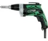
... power tool. NEVER operate, or attempt any maintenance on the tool unless you in this Instruction Manual may show details or attachments that differ from those on your own power tool. NAME OF PARTS Gear Cover Housing Nameplate Gear Cover Housing Nameplate Sub-Stopper (F) Sub-Stopper (B) Locator Lever Switch W6VM • W6V4 • W6VA4 Locator Handle Cover Lever Switch Handle Cover Fig. 1 W6VB3 • W8VB2 SPECIFICATIONS Model W6VM W6V4 W6VA4 W6VB3 W8VB2 Motor...
... power tool. NEVER operate, or attempt any maintenance on the tool unless you in this Instruction Manual may show details or attachments that differ from those on your own power tool. NAME OF PARTS Gear Cover Housing Nameplate Gear Cover Housing Nameplate Sub-Stopper (F) Sub-Stopper (B) Locator Lever Switch W6VM • W6V4 • W6VA4 Locator Handle Cover Lever Switch Handle Cover Fig. 1 W6VB3 • W8VB2 SPECIFICATIONS Model W6VM W6V4 W6VA4 W6VB3 W8VB2 Motor...
Instruction Manual
Page 10
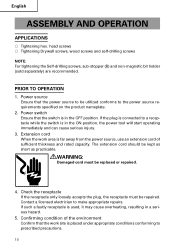
... replaced or repaired. 4. Confirming condition of sufficient thickness and rated capacity. head screws ⅜ Tightening Drywall screws, wood screws and self-drilling screws NOTE: For tightening the Self-drilling screws, sub-stopper (B) and non-magnetic bit holder (sold separately) are recommended. If the plug is connected to the power source requirements specified on the product nameplate. 2. The extension cord should be utilized conforms to a receptacle while the switch...
... replaced or repaired. 4. Confirming condition of sufficient thickness and rated capacity. head screws ⅜ Tightening Drywall screws, wood screws and self-drilling screws NOTE: For tightening the Self-drilling screws, sub-stopper (B) and non-magnetic bit holder (sold separately) are recommended. If the plug is connected to the power source requirements specified on the product nameplate. 2. The extension cord should be utilized conforms to a receptacle while the switch...

Instruction Manual
Page 11
...-drilling screws (Fig. 6) Mount a self-drilling screw on the bit, and set to loosen and remove screws. head Sub-Stopper (B) screw Fig. 4 0.06" - 0.07" (1.5 - 2 mm) Drywall screw Sub-Stopper (F) Fig. 5 11 R side Lever Fig. 2 Sub Locator Stopper (B) Gear cover Fig. 3 0.04" - 0.06" (1 - 1.5 mm) Hex. CAUTION: Never change the bit rotating direction while operating the Screw Driver. Adjusting the tightening depth (Fig. 3) The tightening depth can be adjusted by turning locator right and left with click feeling. (1) For hex-head screws...
...-drilling screws (Fig. 6) Mount a self-drilling screw on the bit, and set to loosen and remove screws. head Sub-Stopper (B) screw Fig. 4 0.06" - 0.07" (1.5 - 2 mm) Drywall screw Sub-Stopper (F) Fig. 5 11 R side Lever Fig. 2 Sub Locator Stopper (B) Gear cover Fig. 3 0.04" - 0.06" (1 - 1.5 mm) Hex. CAUTION: Never change the bit rotating direction while operating the Screw Driver. Adjusting the tightening depth (Fig. 3) The tightening depth can be adjusted by turning locator right and left with click feeling. (1) For hex-head screws...

Instruction Manual
Page 12
... trigger switch is released. 3. Turn the power switch OFF before changing the direction of hex-socket (or bit holder) rotation while the motor is released. 2. The switch will be fully transferred to the item "Mounting and dismounting the hex-socket or the bit". 0.04" - 0.06" (1 - 1.5 mm) Self-drilling screw Sub-Stopper (F) Fig. 6 HOW TO USE THE SCREW DRIVER 1. English 8. Rotational speed increases as the trigger switch is pulled, and reaches a maximum speed of the screw...
... trigger switch is released. 3. Turn the power switch OFF before changing the direction of hex-socket (or bit holder) rotation while the motor is released. 2. The switch will be fully transferred to the item "Mounting and dismounting the hex-socket or the bit". 0.04" - 0.06" (1 - 1.5 mm) Self-drilling screw Sub-Stopper (F) Fig. 6 HOW TO USE THE SCREW DRIVER 1. English 8. Rotational speed increases as the trigger switch is pulled, and reaches a maximum speed of the screw...
Instruction Manual
Page 13
... of bit by hand or vise and pull out the bit with pliers. 3. socket Remove sub-stopper (G) as the same manner of hex-head socket and remove Fig. 7 the bit holder, then pull out the bit with pliers. 2. Mounting the hex-socket or the bit Install the bit in the reverse order to tighten the Self-drilling screw into a steel plate, cut material stuck in the magnet bit will...
... of bit by hand or vise and pull out the bit with pliers. 3. socket Remove sub-stopper (G) as the same manner of hex-head socket and remove Fig. 7 the bit holder, then pull out the bit with pliers. 2. Mounting the hex-socket or the bit Install the bit in the reverse order to tighten the Self-drilling screw into a steel plate, cut material stuck in the magnet bit will...

Instruction Manual
Page 14
... properly tightened. B: Code No. In the operation and maintenance of power tools, the safety regulations and standards prescribed in each country must be performed by a Hitachi Authorized Service Center. Inspecting the carbon brushes For your continued safety and electrical shock protection, carbon brush inspection and replacement on the unit exterior with a dried rag or a rag moistened with a new one as soon as excessive wear is noticed. 2. Service parts list...
... properly tightened. B: Code No. In the operation and maintenance of power tools, the safety regulations and standards prescribed in each country must be performed by a Hitachi Authorized Service Center. Inspecting the carbon brushes For your continued safety and electrical shock protection, carbon brush inspection and replacement on the unit exterior with a dried rag or a rag moistened with a new one as soon as excessive wear is noticed. 2. Service parts list...
Instruction Manual
Page 15
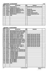
... code numbers and/or design) may be changed without any other attachment or accessory can be dangerous and could cause injury or mechanical damage. NEVER use replacement parts or accessories which are constantly being improved and modified to use a particular replacement part or accessory with this tool. STANDARD ACCESSORIES (1) No. 2 Phillips driver bit (Code No. 971511Z 1 (2) Magnetic bit holder (Code No. 982554Z 1 (3) Sub-stopper (F) (Code No. 323351 1 (1) Magnetic hex. English MODIFICATIONS: Hitachi Power Tools...
... code numbers and/or design) may be changed without any other attachment or accessory can be dangerous and could cause injury or mechanical damage. NEVER use replacement parts or accessories which are constantly being improved and modified to use a particular replacement part or accessory with this tool. STANDARD ACCESSORIES (1) No. 2 Phillips driver bit (Code No. 971511Z 1 (2) Magnetic bit holder (Code No. 982554Z 1 (3) Sub-stopper (F) (Code No. 323351 1 (1) Magnetic hex. English MODIFICATIONS: Hitachi Power Tools...

Instruction Manual
Page 16
...: Specifications are subject to change without any obligation on the part of the HITACHI. 16 For other screws Screw head Type Bit Size No.1 No.2 No.3 No.1 No.2 No.1 No.2 No.3 No.1 No.2 Code No. 985333 971511Z 971512Z 985334 985335 985336 985337 985338 985340 985341 B Size 5/32" (4 mm) 985342 13/64" (5 mm) 985343 Bit holder Magnetic bit holder (Short type) Magnetic bit holder (Code No. 982554Z) Non-magnetic bit bolder (Code No...
...: Specifications are subject to change without any obligation on the part of the HITACHI. 16 For other screws Screw head Type Bit Size No.1 No.2 No.3 No.1 No.2 No.1 No.2 No.3 No.1 No.2 Code No. 985333 971511Z 971512Z 985334 985335 985336 985337 985338 985340 985341 B Size 5/32" (4 mm) 985342 13/64" (5 mm) 985343 Bit holder Magnetic bit holder (Short type) Magnetic bit holder (Code No. 982554Z) Non-magnetic bit bolder (Code No...

Instruction Manual
Page 48
48 W6VM A B CD 1 876-031 1 S-16 2 323-487 1 "3" 3 323-488 1 4 971-468 1 5 317-662 1 6 321-057 3 D4×25 7 323-486 1 "5" 8 872-573 1 9 959-148 2 D3.175 ...
48 W6VM A B CD 1 876-031 1 S-16 2 323-487 1 "3" 3 323-488 1 4 971-468 1 5 317-662 1 6 321-057 3 D4×25 7 323-486 1 "5" 8 872-573 1 9 959-148 2 D3.175 ...
Parts List
Page 2
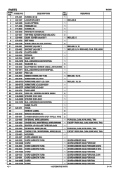
... SPRING GEAR SET BALL BEARING 608VVC2PS2L WASHER (A) SLOTTED HD. HD. PARTS ITEM NO. TAPPING SCREW D4X50 340-599C STATOR 110V-120V 340-599E STATOR 220V-240V 608-VVM BALL BEARING 608VVC2PS2L NAME PLATE 323-471 HOOK HITACHI LABEL 323-512 BRUSH HOLDER (A) 999-091 CARBON BRUSH (AUTO STOP TYPE) (1 PAIR) 323-489 INTERNAL WIRE (BROWN) 323-480 CHOKE COIL (W/INTERNAL WIRE) BROWN 323-479 SWITCH (1P PILLAR TYPE) W/LOCK...
... SPRING GEAR SET BALL BEARING 608VVC2PS2L WASHER (A) SLOTTED HD. HD. PARTS ITEM NO. TAPPING SCREW D4X50 340-599C STATOR 110V-120V 340-599E STATOR 220V-240V 608-VVM BALL BEARING 608VVC2PS2L NAME PLATE 323-471 HOOK HITACHI LABEL 323-512 BRUSH HOLDER (A) 999-091 CARBON BRUSH (AUTO STOP TYPE) (1 PAIR) 323-489 INTERNAL WIRE (BROWN) 323-480 CHOKE COIL (W/INTERNAL WIRE) BROWN 323-479 SWITCH (1P PILLAR TYPE) W/LOCK...

Parts List
Page 3
CODE NO. USED REMARKS * 38 500-409Z CORD 1 (CORD ARMOR D8.8) FOR KOR 39 937-631 CORD CLIP 1 40 984-750 TAPPING SCREW (W/FLANGE) D4X16 2 * 41 959-140 CONNECTOR 50091 (10 PCS.) 2 EXCEPT FOR USA, CAN, KUW, HKG, THA * 42 930-039 NOISE SUPPRESSOR 1 EXCEPT ...EXCEPT FOR USA, CAN, KUW, HKG, THA * 44 317-667 INTERNAL WIRE 2 EXCEPT FOR USA, CAN, KUW, HKG, THA * 45 992-635 EARTH TERMINAL 1 EXCEPT FOR USA, CAN, KUW, HKG, THA 46 323-484 HANDLE COVER 1 47 301-653 TAPPING SCREW (W/FLANGE) D4X20 (BLACK) 3 W 6VM 8 -- 04 * ALTERNATIVE PARTS --- 3 --- PARTS ITEM NO. DESCRIPTION NO.
CODE NO. USED REMARKS * 38 500-409Z CORD 1 (CORD ARMOR D8.8) FOR KOR 39 937-631 CORD CLIP 1 40 984-750 TAPPING SCREW (W/FLANGE) D4X16 2 * 41 959-140 CONNECTOR 50091 (10 PCS.) 2 EXCEPT FOR USA, CAN, KUW, HKG, THA * 42 930-039 NOISE SUPPRESSOR 1 EXCEPT ...EXCEPT FOR USA, CAN, KUW, HKG, THA * 44 317-667 INTERNAL WIRE 2 EXCEPT FOR USA, CAN, KUW, HKG, THA * 45 992-635 EARTH TERMINAL 1 EXCEPT FOR USA, CAN, KUW, HKG, THA 46 323-484 HANDLE COVER 1 47 301-653 TAPPING SCREW (W/FLANGE) D4X20 (BLACK) 3 W 6VM 8 -- 04 * ALTERNATIVE PARTS --- 3 --- PARTS ITEM NO. DESCRIPTION NO.
Parts List
Page 4
...FOR THA, HKG, TPE, KOR * 612 982-563Z NON-MAGNETIC BIT HOLDER 1 EXCEPT FOR THA, HKG, TPE, KOR * 613 323-356 MAGNETIC HEX. DRIVER BIT 4MMX25 (W/STEPPED ROD) 1 624 985-341 - BIT 6MMX25L 1 628 310-904 CASE 1 --- 4 --- * ALTERNATIVE PARTS Printed in Japan 8 -- 04 (040825N) SOCKET 3/8" 65L 1 ...OPTIONAL ACCESSORIES ITEM NO. SOCKET 1 REMARKS 602 317-671 SUB STOPPER (B) FOR H5/16 HEX. SOCKET 1/4"X65L 1 EXCEPT FOR THA, HKG, TPE, KOR * 608 985-326 NON-MAGNETIC HEX. DRIVER BIT 8MMX25 1 623 985-340 - CODE NO. DESCRIPTION NO. DRIVER BIT 5MMX25 1 621 985-338 - DRIVER BIT ...
...FOR THA, HKG, TPE, KOR * 612 982-563Z NON-MAGNETIC BIT HOLDER 1 EXCEPT FOR THA, HKG, TPE, KOR * 613 323-356 MAGNETIC HEX. DRIVER BIT 4MMX25 (W/STEPPED ROD) 1 624 985-341 - BIT 6MMX25L 1 628 310-904 CASE 1 --- 4 --- * ALTERNATIVE PARTS Printed in Japan 8 -- 04 (040825N) SOCKET 3/8" 65L 1 ...OPTIONAL ACCESSORIES ITEM NO. SOCKET 1 REMARKS 602 317-671 SUB STOPPER (B) FOR H5/16 HEX. SOCKET 1/4"X65L 1 EXCEPT FOR THA, HKG, TPE, KOR * 608 985-326 NON-MAGNETIC HEX. DRIVER BIT 8MMX25 1 623 985-340 - CODE NO. DESCRIPTION NO. DRIVER BIT 5MMX25 1 621 985-338 - DRIVER BIT ...


