
Instruction Manual
Page 3
... avoided by WARNINGS on the power tool and in this Instruction Manual. NEVER use this power tool in a manner that result from power tool operation and maintenance are caused by the failure to prevent bodily injury or machine damage are outlined in the "SAFETY" section of the safety precautions, warnings and operating instructions in the Instruction Manual before it occurs, and by HITACHI. NOTE emphasizes essential information. 3 MEANINGS...
... avoided by WARNINGS on the power tool and in this Instruction Manual. NEVER use this power tool in a manner that result from power tool operation and maintenance are caused by the failure to prevent bodily injury or machine damage are outlined in the "SAFETY" section of the safety precautions, warnings and operating instructions in the Instruction Manual before it occurs, and by HITACHI. NOTE emphasizes essential information. 3 MEANINGS...

Instruction Manual
Page 4
... abuse the cord. Be sure switch is grounded. (3) Don't expose power tools to carry the tools or pull the plug from a receptacle. Failure to install a polarized outlet. Electrical Safety (1) Double Insulated tools are rated for the three wire grounded power cord and grounded power supply system. (2) Avoid body contact with your work area clean and well lit. Water entering a power tool will fit in electric shock, fire...
... abuse the cord. Be sure switch is grounded. (3) Don't expose power tools to carry the tools or pull the plug from a receptacle. Failure to install a polarized outlet. Electrical Safety (1) Double Insulated tools are rated for the three wire grounded power cord and grounded power supply system. (2) Avoid body contact with your work area clean and well lit. Water entering a power tool will fit in electric shock, fire...

Instruction Manual
Page 5
... to a rotating part of untrained users. (6) Maintain tools with the switch is dangerous and must be repaired. (4) Disconnect the plug form the power source before making any adjustments, changing accessories, or storing the tool. Follow instructions in the Maintenance section of the tool in a risk of electric shock or injury. 5 A wrench or a key that may be performed only by the manufacturer for appropriate conditions. 4. Service (1) Tool service must be...
... to a rotating part of untrained users. (6) Maintain tools with the switch is dangerous and must be repaired. (4) Disconnect the plug form the power source before making any adjustments, changing accessories, or storing the tool. Follow instructions in the Maintenance section of the tool in a risk of electric shock or injury. 5 A wrench or a key that may be performed only by the manufacturer for appropriate conditions. 4. Service (1) Tool service must be...

Instruction Manual
Page 6
... parts near the tool's moving parts. Using any wheel a rated capacity LESS than those specified in place. NEVER use tool for purpose not intended -for cutting tree limbs or logs. 9. NEVER operate without all guards in the Instruction Manual. 6 Wheels and other than 13,300 RPM and/or an incorrect sized wheel (see SPECIFICATIONS at least the speed recommended on the tool warning label. ALWAYS use circular saw for example- Don't use a power tool...
... parts near the tool's moving parts. Using any wheel a rated capacity LESS than those specified in place. NEVER use tool for purpose not intended -for cutting tree limbs or logs. 9. NEVER operate without all guards in the Instruction Manual. 6 Wheels and other than 13,300 RPM and/or an incorrect sized wheel (see SPECIFICATIONS at least the speed recommended on the tool warning label. ALWAYS use circular saw for example- Don't use a power tool...

Instruction Manual
Page 7
... to a complete stop using the power tool at voltages specified on page 15). 21. If using it will result in the tool's housing or handle can lead to electric shock. NEVER use a depressed center wheel which is cracked. Turn power off. Solvents such as where flammable materials or gases are present. 22. Blades, cutting implements and accessories which have been mounted to the tool should not be...
... to a complete stop using the power tool at voltages specified on page 15). 21. If using it will result in the tool's housing or handle can lead to electric shock. NEVER use a depressed center wheel which is cracked. Turn power off. Solvents such as where flammable materials or gases are present. 22. Blades, cutting implements and accessories which have been mounted to the tool should not be...
Instruction Manual
Page 8
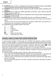
... grip the body handle and side handle while operating the grinder. 26. ALWAYS have been used on page 12). 27. Touching these precautions: ⅜ Only HITACHI AUTHORIZED SERVICE CENTER should disassemble or assemble this power tool, and only genuine HITACHI replacement parts should be careful with soapy water, and dry thoroughly. Never use solvents, gasoline or thinners on the nameplate. ALWAYS be installed. ⅜ Clean...
... grip the body handle and side handle while operating the grinder. 26. ALWAYS have been used on page 12). 27. Touching these precautions: ⅜ Only HITACHI AUTHORIZED SERVICE CENTER should disassemble or assemble this power tool, and only genuine HITACHI replacement parts should be careful with soapy water, and dry thoroughly. Never use solvents, gasoline or thinners on the nameplate. ALWAYS be installed. ⅜ Clean...

Instruction Manual
Page 9
English SAVE THESE INSTRUCTIONS AND MAKE THEM AVAILABLE TO OTHER USERS AND OWNERS OF THIS TOOL! 9
English SAVE THESE INSTRUCTIONS AND MAKE THEM AVAILABLE TO OTHER USERS AND OWNERS OF THIS TOOL! 9

Instruction Manual
Page 10
.... NAME OF PARTS Push Button Switch Gear Cover Housing Tail Cover Depressed Center Wheel Packing Gland SPECIFICATIONS Side Handle Wheel Guard Fig.1 Model Motor Power Source Current No-Load Speed Wheel Size: external diam. NEVER operate, or attempt any maintenance on your own power tool. English FUNCTIONAL DESCRIPTION NOTE: The information contained in this Instruction Manual is designed to assist you have first read and understood all safety instructions contained in this Instruction Manual may show...
.... NAME OF PARTS Push Button Switch Gear Cover Housing Tail Cover Depressed Center Wheel Packing Gland SPECIFICATIONS Side Handle Wheel Guard Fig.1 Model Motor Power Source Current No-Load Speed Wheel Size: external diam. NEVER operate, or attempt any maintenance on your own power tool. English FUNCTIONAL DESCRIPTION NOTE: The information contained in this Instruction Manual is designed to assist you have first read and understood all safety instructions contained in this Instruction Manual may show...
Instruction Manual
Page 11
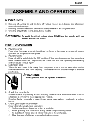
... conforms to make appropriate repairs. Check your work area is in the OFF position. If the plug is connected to a receptacle while the switch is far away from the power source, use this grinder with cup wheels and/or saw blades. WARNING: Damaged cord must be kept as short as practicable. Power source Ensure that the switch is used, it may cause overheating...
... conforms to make appropriate repairs. Check your work area is in the OFF position. If the plug is connected to a receptacle while the switch is far away from the power source, use this grinder with cup wheels and/or saw blades. WARNING: Damaged cord must be kept as short as practicable. Power source Ensure that the switch is used, it may cause overheating...

Instruction Manual
Page 12
... to fix it is replaced 3 minutes or more When starting daily work , test the grinder by first clearing the area of the trial run is as follows: When depressed center wheel is firmly clamped and has been properly mounted. Fig. 2 Make sure it Wheel Guard completely. Turn the grinder "on the wheel guard. Duration of all other abnomalities before using. Test the grinder before mounting. English 6. Mounting the wheel guard...
... to fix it is replaced 3 minutes or more When starting daily work , test the grinder by first clearing the area of the trial run is as follows: When depressed center wheel is firmly clamped and has been properly mounted. Fig. 2 Make sure it Wheel Guard completely. Turn the grinder "on the wheel guard. Duration of all other abnomalities before using. Test the grinder before mounting. English 6. Mounting the wheel guard...
Instruction Manual
Page 13
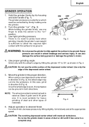
.... 4 6. Use light grinding pressure. Turn the grinder "on " position. 3. CAUTION: Do not use one finger to slide the switch to 30°, as Class A grain and # 36 grain size. Once the wheel edge is worn, the workpiece can be ground. When using a new depressed center wheel in areas of the depressed center wheel. Heavy pressure can also damage the surface being ground or damage the grinder's motor...
.... 4 6. Use light grinding pressure. Turn the grinder "on " position. 3. CAUTION: Do not use one finger to slide the switch to 30°, as Class A grain and # 36 grain size. Once the wheel edge is worn, the workpiece can be ground. When using a new depressed center wheel in areas of the depressed center wheel. Heavy pressure can also damage the surface being ground or damage the grinder's motor...

Instruction Manual
Page 14
... turning the Wheel Nut depressed center wheel slowly with one Wrench hand, lock the spindle by using the supplied Wheel wrench as shown in the "OFF" position and the electrical cord has been disconnected from the receptacle. 1. Spindle 2. Disassembly To remove the depressed center wheel, simply reverse the above-mentioned procedure. Wheel Washer CAUTION: Tighten the wheel nut securely and confirm that the spindle is in Fig. 5. Wheel Guard Push Button Fig. 5 14 Assembly (1) Turn the disc grinder...
... turning the Wheel Nut depressed center wheel slowly with one Wrench hand, lock the spindle by using the supplied Wheel wrench as shown in the "OFF" position and the electrical cord has been disconnected from the receptacle. 1. Spindle 2. Disassembly To remove the depressed center wheel, simply reverse the above-mentioned procedure. Wheel Washer CAUTION: Tighten the wheel nut securely and confirm that the spindle is in Fig. 5. Wheel Guard Push Button Fig. 5 14 Assembly (1) Turn the disc grinder...
Instruction Manual
Page 15
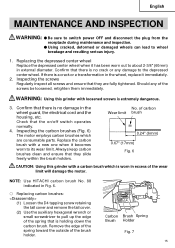
...) Fig. 6 CAUTION: Using this grinder with loosened screws is a crack or a transformation in the wheel guard, the electrical cord and the housing, etc. Remove the edge of the spring toward the outside of the spring that there is worn in Fig. 6. ⅜ Replacing carbon brushes: (1) Loosen the D4 tapping screw retaining the tail cover and remove the tail cover. (2) Use the auxiliary hexagonal wrench or small screwdriver to its...
...) Fig. 6 CAUTION: Using this grinder with loosened screws is a crack or a transformation in the wheel guard, the electrical cord and the housing, etc. Remove the edge of the spring toward the outside of the spring that there is worn in Fig. 6. ⅜ Replacing carbon brushes: (1) Loosen the D4 tapping screw retaining the tail cover and remove the tail cover. (2) Use the auxiliary hexagonal wrench or small screwdriver to its...
Instruction Manual
Page 16
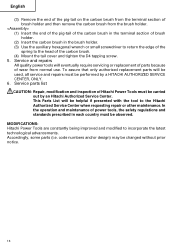
... Hitachi Authorized Service Center when requesting repair or other maintenance. This Parts List will be used, all service and repairs must be observed. code numbers and/or design) may be carried out by a HITACHI AUTHORIZED SERVICE CENTER, ONLY. 6. MODIFICATIONS: Hitachi Power Tools are constantly being improved and modified to the head of power tools, the safety regulations and standards prescribed in the brush holder. (3) Use the auxiliary hexagonal wrench or small screwdriver to return the edge...
... Hitachi Authorized Service Center when requesting repair or other maintenance. This Parts List will be used, all service and repairs must be observed. code numbers and/or design) may be carried out by a HITACHI AUTHORIZED SERVICE CENTER, ONLY. 6. MODIFICATIONS: Hitachi Power Tools are constantly being improved and modified to the head of power tools, the safety regulations and standards prescribed in the brush holder. (3) Use the auxiliary hexagonal wrench or small screwdriver to return the edge...
Instruction Manual
Page 17
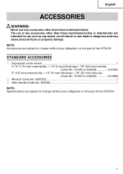
...; Wrench (Code No. 938332Z 1 ⅜ Side Handle (Code No. 994322 1 NOTE: Specifications are subject to change without any accessories other than those mentioned below or attachments not intended for use such as cup wheel, cut-off wheel or saw blade is dangerous and may cause personal injury or property damage. The use of any obligation on the part of the HITACHI. 17 NOTE: Accessories are subject to change...
...; Wrench (Code No. 938332Z 1 ⅜ Side Handle (Code No. 994322 1 NOTE: Specifications are subject to change without any accessories other than those mentioned below or attachments not intended for use such as cup wheel, cut-off wheel or saw blade is dangerous and may cause personal injury or property damage. The use of any obligation on the part of the HITACHI. 17 NOTE: Accessories are subject to change...
Parts List
Page 1
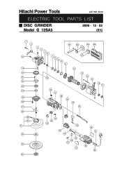
E272 ELECTRIC TOOL PARTS LIST DISC GRINDER Model G 12SA3 2005 • 12 • 23 (E1) 1 2 18 19 20 21 22 23 24 25 26 27 28 29 30 31 32 33 34 501 502 3 4 5 6 7 8 9 10 11 503 504 12 13 14 35 15 36 37 38 39 40 41 16 17 44 43 42 55 45 46 49 48 47 52 50 51 53 54 Hitachi Power Tools LIST NO.
E272 ELECTRIC TOOL PARTS LIST DISC GRINDER Model G 12SA3 2005 • 12 • 23 (E1) 1 2 18 19 20 21 22 23 24 25 26 27 28 29 30 31 32 33 34 501 502 3 4 5 6 7 8 9 10 11 503 504 12 13 14 35 15 36 37 38 39 40 41 16 17 44 43 42 55 45 46 49 48 47 52 50 51 53 54 Hitachi Power Tools LIST NO.

Parts List
Page 2
...-536 SPRING 2 45 325-054 SWITCH HOLDER 1 --- 2 --- * ALTERNATIVE PARTS G 12SA3 12 -- 05 PARTS ITEM NO. TAPPING SCREW D4X70 2 * 15 340-645D STATOR 120V 1 * 15 340-645E STATOR 230V 1 * 15 340-645F STATOR 240V 1 16 315-877 DUST SEAL 1 17 608-VVM BALL BEARING 608VVC2PS2L 1 18 303-255 SEAL LOCK SCREW (W/SP. C. WASHER) M4X10 2 19 301-943 LOCK PIN 1 20 321-736 GEAR 1 21...
...-536 SPRING 2 45 325-054 SWITCH HOLDER 1 --- 2 --- * ALTERNATIVE PARTS G 12SA3 12 -- 05 PARTS ITEM NO. TAPPING SCREW D4X70 2 * 15 340-645D STATOR 120V 1 * 15 340-645E STATOR 230V 1 * 15 340-645F STATOR 240V 1 16 315-877 DUST SEAL 1 17 608-VVM BALL BEARING 608VVC2PS2L 1 18 303-255 SEAL LOCK SCREW (W/SP. C. WASHER) M4X10 2 19 301-943 LOCK PIN 1 20 321-736 GEAR 1 21...

Parts List
Page 3
USED 2 REMARKS 2 1 1 1 2 1 1 1 (CORD ARMOR D8.8) 1 (CORD ARMOR D8.8) FOR KUW 1 (CORD ARMOR D8.8) FOR USA, CAN 1 (CORD ARMOR D8.8) FOR GBR 1 (CORD ARMOR D8.8) FOR NZL 1 FOR NOISE SUPPRESSOR G 12SA3 12 -- 05 * ALTERNATIVE PARTS --- 3 --- PARTS ITEM NO. CODE NO. 46 980-063 TERMINAL DESCRIPTION 47 984-750 TAPPING SCREW (W/FLANGE) D4X16 48 937-631 CORD CLIP 49 953-327 CORD ARMOR D8.8 50...
USED 2 REMARKS 2 1 1 1 2 1 1 1 (CORD ARMOR D8.8) 1 (CORD ARMOR D8.8) FOR KUW 1 (CORD ARMOR D8.8) FOR USA, CAN 1 (CORD ARMOR D8.8) FOR GBR 1 (CORD ARMOR D8.8) FOR NZL 1 FOR NOISE SUPPRESSOR G 12SA3 12 -- 05 * ALTERNATIVE PARTS --- 3 --- PARTS ITEM NO. CODE NO. 46 980-063 TERMINAL DESCRIPTION 47 984-750 TAPPING SCREW (W/FLANGE) D4X16 48 937-631 CORD CLIP 49 953-327 CORD ARMOR D8.8 50...

Parts List
Page 4
... 502 994-322 SIDE HANDLE 1 * 503 325-496 SIDE HANDLE (VIBRATION-ABSORBING) 1 FOR EUROPE * 504 325-515 CASE 1 FOR EUROPE G 12SA3 OPTIONAL ACCESSORIES ITEM NO. USED * 601 937-825Z RUBBER PAD 1 REMARKS * 601 938-317 RUBBER PAD 1 FOR USA, CAN * 602 937-826Z WASHER NUT 1 * 602 938-318 WASHER NUT 1 FOR USA, CAN 603 314-095 SANDING DISCS 115MM C-P16 (10 PCS...
... 502 994-322 SIDE HANDLE 1 * 503 325-496 SIDE HANDLE (VIBRATION-ABSORBING) 1 FOR EUROPE * 504 325-515 CASE 1 FOR EUROPE G 12SA3 OPTIONAL ACCESSORIES ITEM NO. USED * 601 937-825Z RUBBER PAD 1 REMARKS * 601 938-317 RUBBER PAD 1 FOR USA, CAN * 602 937-826Z WASHER NUT 1 * 602 938-318 WASHER NUT 1 FOR USA, CAN 603 314-095 SANDING DISCS 115MM C-P16 (10 PCS...


