Instruction Manual
Page 3
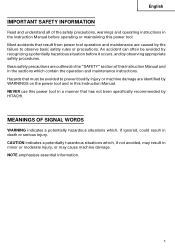
... failure to prevent bodily injury or machine damage are outlined in the "SAFETY" section of the safety precautions, warnings and operating instructions in the Instruction Manual before it occurs, and by HITACHI. Hazards that result from power tool operation and maintenance are caused by WARNINGS on the power tool and in this Instruction Manual and in minor or moderate injury, or may cause machine damage...
... failure to prevent bodily injury or machine damage are outlined in the "SAFETY" section of the safety precautions, warnings and operating instructions in the Instruction Manual before it occurs, and by HITACHI. Hazards that result from power tool operation and maintenance are caused by WARNINGS on the power tool and in this Instruction Manual and in minor or moderate injury, or may cause machine damage...
Instruction Manual
Page 4
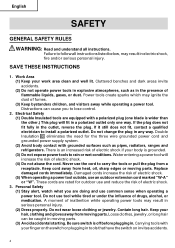
... from a receptacle. SAVE THESE INSTRUCTIONS 1. Never use an outdoor extension cord marked "W-A" or "W". Electrical Safety (1) Double Insulated tools are rated for the three wire grounded power cord and grounded power supply system. (2) Avoid body contact with a polarized plug (one blade is off before plugging in a polarized outlet only one way. Double Insulation eliminates the need for outdoor use and reduce the risk of...
... from a receptacle. SAVE THESE INSTRUCTIONS 1. Never use an outdoor extension cord marked "W-A" or "W". Electrical Safety (1) Double Insulated tools are rated for the three wire grounded power cord and grounded power supply system. (2) Avoid body contact with a polarized plug (one blade is off before plugging in a polarized outlet only one way. Double Insulation eliminates the need for outdoor use and reduce the risk of...
Instruction Manual
Page 5
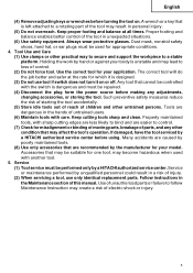
... use only identical replacement parts. Service or maintenance performed by hand or against your body is left attached to a stable platform. English (4) Remove adjusting keys or wrenches before using. Tools are easier to bind and are dangerous in a risk of control. (2) Do not force tool. Service (1) Tool service must be performed only by the manufacturer for your model. Use of unauthorized parts or failure to loss of injury. (2) When servicing a tool, use tool...
... use only identical replacement parts. Service or maintenance performed by hand or against your body is left attached to a stable platform. English (4) Remove adjusting keys or wrenches before using. Tools are easier to bind and are dangerous in a risk of control. (2) Do not force tool. Service (1) Tool service must be performed only by the manufacturer for your model. Use of unauthorized parts or failure to loss of injury. (2) When servicing a tool, use tool...
Instruction Manual
Page 6
... an operation where the cutting tool may contact hidden wiring or its operation or unauthorized personnel. 11. NEVER touch moving parts. 7. NEVER allow the tool to replace the guard or safety feature before resuming operation of the tool "live" and shock the operator. 2. Do not use circular saw for cutting tree limbs or logs. 9. NEVER operate without all screws, bolts and covers tightly in place. Contact with bare hands after operation...
... an operation where the cutting tool may contact hidden wiring or its operation or unauthorized personnel. 11. NEVER touch moving parts. 7. NEVER allow the tool to replace the guard or safety feature before resuming operation of the tool "live" and shock the operator. 2. Do not use circular saw for cutting tree limbs or logs. 9. NEVER operate without all screws, bolts and covers tightly in place. Contact with bare hands after operation...
Instruction Manual
Page 7
... handle power tools. Should a power tool be securely mounted to youself or others. Blades, cutting implements and accessories which is defective or operating abnormally. Wipe plastic parts with a soft cloth lightly dampened with solvent. Blades and accessories must be kept clean so that meets the requirement of the latest revision of ANSI Standard Z87.1. 21. hertz A amperes no load speed W watt Class II Construction ---/min ... Keep motor air...
... handle power tools. Should a power tool be securely mounted to youself or others. Blades, cutting implements and accessories which is defective or operating abnormally. Wipe plastic parts with a soft cloth lightly dampened with solvent. Blades and accessories must be kept clean so that meets the requirement of the latest revision of ANSI Standard Z87.1. 21. hertz A amperes no load speed W watt Class II Construction ---/min ... Keep motor air...

Instruction Manual
Page 8
... follow these precautions: ⅜ Only HITACHI AUTHORIZED SERVICE CENTER should be installed. ⅜ Clean the exterior of this power tool, HITACHI has adopted a double insulation design. To keep the double insulation system effective, follow the normal electrical safety precautions given in this power tool, and only genuine HITACHI replacement parts should disassemble or assemble this Instruction Manual, including not using the power tool in wet environments. "Double insulation " means...
... follow these precautions: ⅜ Only HITACHI AUTHORIZED SERVICE CENTER should be installed. ⅜ Clean the exterior of this power tool, HITACHI has adopted a double insulation design. To keep the double insulation system effective, follow the normal electrical safety precautions given in this power tool, and only genuine HITACHI replacement parts should disassemble or assemble this Instruction Manual, including not using the power tool in wet environments. "Double insulation " means...
Instruction Manual
Page 9
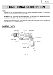
Some illustrations in this manual. NEVER operate, or attempt any maintenance on your own power tool NAME OF PARTS Gear Cover Housing Nameplate Drill Chuck Side Handle Switch Trigger Handle Cover Push Button Stopper Fig. 1 9 English FUNCTIONAL DESCRIPTION NOTE: The information contained in this Instruction Manual is designed to assist you in this Instruction Manual may show details or attachments that differ from those on the tool unless you have first read and understood all safety instructions contained in the safe operation and maintenance of the power tool.
Some illustrations in this manual. NEVER operate, or attempt any maintenance on your own power tool NAME OF PARTS Gear Cover Housing Nameplate Drill Chuck Side Handle Switch Trigger Handle Cover Push Button Stopper Fig. 1 9 English FUNCTIONAL DESCRIPTION NOTE: The information contained in this Instruction Manual is designed to assist you in this Instruction Manual may show details or attachments that differ from those on the tool unless you have first read and understood all safety instructions contained in the safe operation and maintenance of the power tool.
Instruction Manual
Page 11
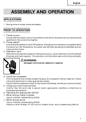
... drill bit. However, when drilling 1/4" (6.5 mm) or smaller holes, use an extension cord of sufficient thickness and rated capacity. The extension cord should be utilized conforms to a receptacle while the switch is in the ON position, the power tool will start operating immediately and can cause serious injury. 3. If such a fautly receptacle is far away from the power source, use a metalworking drill bit. 11 English ASSEMBLY...
... drill bit. However, when drilling 1/4" (6.5 mm) or smaller holes, use an extension cord of sufficient thickness and rated capacity. The extension cord should be utilized conforms to a receptacle while the switch is in the ON position, the power tool will start operating immediately and can cause serious injury. 3. If such a fautly receptacle is far away from the power source, use a metalworking drill bit. 11 English ASSEMBLY...
Instruction Manual
Page 12
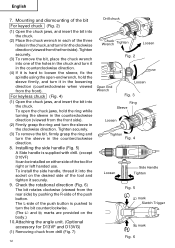
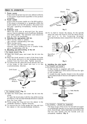
... the bit For keyed chuck (Fig. 2) (1) Open the chuck jaws, and insert the bit into the chuck. Installing the side handle (Fig. 5) A Side handle is pushed to loosen the sleeve, fix the spindle using the open the chuck jaws, hold the sleeve firmly, and turn it in the loosening direction (counterclockwise when viewed from the front). Mounting and dismounting of the push button is supplied with drill. (except D10VF) It...
... the bit For keyed chuck (Fig. 2) (1) Open the chuck jaws, and insert the bit into the chuck. Installing the side handle (Fig. 5) A Side handle is pushed to loosen the sleeve, fix the spindle using the open the chuck jaws, hold the sleeve firmly, and turn it in the loosening direction (counterclockwise when viewed from the front). Mounting and dismounting of the push button is supplied with drill. (except D10VF) It...
Instruction Manual
Page 13
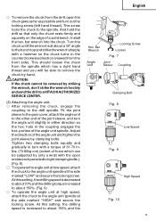
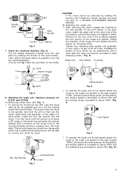
... chuck turns in the coupling engages the hex. Tighten two clamping bolts equally and gradually in turn with the open the chuck jaws as far as possible and turn the angle unit slightly in either direction so the hex. bar wrench into the chuck. Adjust the direction of a solid bench. At this setting, the drilling speed is decreased to about 70% and the drilling torque increased to remove the chuck...
... chuck turns in the coupling engages the hex. Tighten two clamping bolts equally and gradually in turn with the open the chuck jaws as far as possible and turn the angle unit slightly in either direction so the hex. bar wrench into the chuck. Adjust the direction of a solid bench. At this setting, the drilling speed is decreased to about 70% and the drilling torque increased to remove the chuck...
Instruction Manual
Page 14
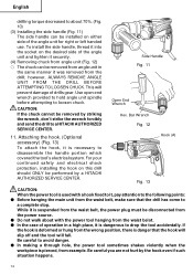
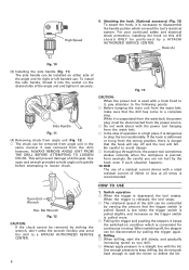
...tool accidentally. English drilling torque decreased to about with a hook fixed to it is deformed or hung from the drill; Use open end wrench provided to hold angle unit spindle before attempting to a HITACHI AUTHORIZED SERVICE CENTER. 11. Bar Wrench Fig. 12 Hook (A) Fig. 13 CAUTION: When the power tool is pierced, from the waist belt...This will fall. For your continued safety and electrical shock protection, installing the hook on either side of drills gear. Side Handle Fig. 11 Open End Wrench Hex. CAUTION: If the chuck cannot be removed by the hook even if such situation...
...tool accidentally. English drilling torque decreased to about with a hook fixed to it is deformed or hung from the drill; Use open end wrench provided to hold angle unit spindle before attempting to a HITACHI AUTHORIZED SERVICE CENTER. 11. Bar Wrench Fig. 12 Hook (A) Fig. 13 CAUTION: When the power tool is pierced, from the waist belt...This will fall. For your continued safety and electrical shock protection, installing the hook on either side of drills gear. Side Handle Fig. 11 Open End Wrench Hex. CAUTION: If the chuck cannot be removed by the hook even if such situation...
Instruction Manual
Page 15
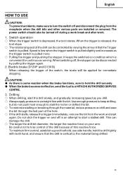
... to turn the switch off and disconnect the plug from the work . 1. The power switch should also be controlled by pulling the trigger again. 2. Switch operation ⅜ When the trigger switch is released, the tool stops. ⅜ The rotational speed of the hole. ⅜ If the drill stalls, release the trigger immediately, remove the bit from the receptacle when the drill bits and other various parts are installed or removed. Speed is low when the trigger switch...
... to turn the switch off and disconnect the plug from the work . 1. The power switch should also be controlled by pulling the trigger again. 2. Switch operation ⅜ When the trigger switch is released, the tool stops. ⅜ The rotational speed of the hole. ⅜ If the drill stalls, release the trigger immediately, remove the bit from the receptacle when the drill bits and other various parts are installed or removed. Speed is low when the trigger switch...
Instruction Manual
Page 16
... fully tightened. Inspecting the carbon brushes For your continued safety and electrical shock protection, carbon brush inspection and replacement on this drill with oil or water. 6. Exercise due care to switch power OFF and disconnect the plug from normal use. Inspecting the drill bits Since use , the Power tool should ONLY be loosened, retighten them immediately. Service and repairs All quality power tools will be used, all screws and ensure that only authorized replacement parts will...
... fully tightened. Inspecting the carbon brushes For your continued safety and electrical shock protection, carbon brush inspection and replacement on this drill with oil or water. 6. Exercise due care to switch power OFF and disconnect the plug from normal use. Inspecting the drill bits Since use , the Power tool should ONLY be loosened, retighten them immediately. Service and repairs All quality power tools will be used, all screws and ensure that only authorized replacement parts will...

Parts List
Page 2
... PUSHING BUTTON 1 SWITCH (1P SCREW TYPE) W/LOCK 1 FOR USA,CAN,GBR (110V) SWITCH (1P SCREW TYPE) W/LOCK 1 FOR NZL,EUROPE TAPPING SCREW (W/FLANGE) D4X16 2 CORD CLIP 1 TUBE (D) 2 CORD ARMOR D8.8 1 CORD 1 (CORD ARMOR D8.8) FOR USA,CAN CORD 1 (CORD ARMOR D8.8) FOR NZL CORD 1 (CORD ARMOR D8.8) FOR GBR (110V) * ALTERNATIVE PARTS D 10VF 8-- 01 HD. DESCRIPTION SPECIAL SCREW (LEFT HAND) M6X23 NO. PARTS ITEM NO. USED 1 REMARKS CHUCK WRENCH 10VLR-J 1 VINYL BAND 1 DRILL CHUCK 10VLR-J 1 INCLUD.2 DRILL CHUCK 10VLRD-N (W/O CHUCK WRENCH) 1 SPINDLE...
... PUSHING BUTTON 1 SWITCH (1P SCREW TYPE) W/LOCK 1 FOR USA,CAN,GBR (110V) SWITCH (1P SCREW TYPE) W/LOCK 1 FOR NZL,EUROPE TAPPING SCREW (W/FLANGE) D4X16 2 CORD CLIP 1 TUBE (D) 2 CORD ARMOR D8.8 1 CORD 1 (CORD ARMOR D8.8) FOR USA,CAN CORD 1 (CORD ARMOR D8.8) FOR NZL CORD 1 (CORD ARMOR D8.8) FOR GBR (110V) * ALTERNATIVE PARTS D 10VF 8-- 01 HD. DESCRIPTION SPECIAL SCREW (LEFT HAND) M6X23 NO. PARTS ITEM NO. USED 1 REMARKS CHUCK WRENCH 10VLR-J 1 VINYL BAND 1 DRILL CHUCK 10VLR-J 1 INCLUD.2 DRILL CHUCK 10VLRD-N (W/O CHUCK WRENCH) 1 SPINDLE...

Handling Instructions
Page 2
... (corded) power tool or battery-operated (cordless) power tool. 1) Work area safety a) Keep work to lose control. 2) Electrical safety a) Power tool plugs must be stored out of reach of electric shock. Loose clothes, jewellery or long hair can be performed. g) If devices are caused by a qualified repair person using only identical replacement parts. Use of parts and any way. Use the correct power tool for the connection of the power tool is earthed or grounded. The correct power tool...
... (corded) power tool or battery-operated (cordless) power tool. 1) Work area safety a) Keep work to lose control. 2) Electrical safety a) Power tool plugs must be stored out of reach of electric shock. Loose clothes, jewellery or long hair can be performed. g) If devices are caused by a qualified repair person using only identical replacement parts. Use of parts and any way. Use the correct power tool for the connection of the power tool is earthed or grounded. The correct power tool...
Handling Instructions
Page 3
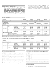
... up such as it is subject to change by areas)* Power input No load speed Drill chuck capacity Steel Twist Bit Hole Saw Capacity Flat Spade Bit Wood Auger Bit Hole Saw Weight (without notice. DRILL SAFETY WARNINGS 1. Use auxiliary handle(s), if supplied with the tool. Do not wear gloves made of control can cause personal injury. 2. for keyed chuck) ........ 1 (1) Side handle 1 (2) Handle joint 1 (3) Chuck wrench (Spec. SPECIFICATIONS Model Voltage (by areas. only for keyed chuck) ...... 1 (1) Side handle 1 (2)Chuck wrench (Spec.
... up such as it is subject to change by areas)* Power input No load speed Drill chuck capacity Steel Twist Bit Hole Saw Capacity Flat Spade Bit Wood Auger Bit Hole Saw Weight (without notice. DRILL SAFETY WARNINGS 1. Use auxiliary handle(s), if supplied with the tool. Do not wear gloves made of control can cause personal injury. 2. for keyed chuck) ........ 1 (1) Side handle 1 (2) Handle joint 1 (3) Chuck wrench (Spec. SPECIFICATIONS Model Voltage (by areas. only for keyed chuck) ...... 1 (1) Side handle 1 (2)Chuck wrench (Spec.
Handling Instructions
Page 4
... Use ordinary woodworking drill bits. It can result in the counterclockwise direction. Loosen Side Handle Tighten Fig. 4 For D13VG D13VF for Australia The large torque of the tool and tighten it in the loosening direction (counterclockwise when viewed from the front side). Extension cord When the work . Power switch Ensure that the side handle and the handle joint are completely installed. (Fig. 5) 4 Tighten securely. (3) To remove the bit, place the chuck wrench...
... Use ordinary woodworking drill bits. It can result in the counterclockwise direction. Loosen Side Handle Tighten Fig. 4 For D13VG D13VF for Australia The large torque of the tool and tighten it in the loosening direction (counterclockwise when viewed from the front side). Extension cord When the work . Power switch Ensure that the side handle and the handle joint are completely installed. (Fig. 5) 4 Tighten securely. (3) To remove the bit, place the chuck wrench...
Handling Instructions
Page 5
... turn the bit counterclockwise. (The L and R marks are provided on the edge of the push button is at low speed, attach the chuck to the drill spindle. hole in the counterclockwise direction (viewed from the rear side) by clamping bolts. Bar Wrench Locking Screw Loosen Fig. 7 5 The L-side of a solid bench. This screw locks the chuck to the bench top and strike the wrench sharply with a torque of...
... turn the bit counterclockwise. (The L and R marks are provided on the edge of the push button is at low speed, attach the chuck to the drill spindle. hole in the counterclockwise direction (viewed from the rear side) by clamping bolts. Bar Wrench Locking Screw Loosen Fig. 7 5 The L-side of a solid bench. This screw locks the chuck to the bench top and strike the wrench sharply with a torque of...
Handling Instructions
Page 6
... walk about with the bit. Switch operation ⅜ When the trigger is recommended. Use enough pressure to keep drilling, but do not push hard enough to loosen chuck. RCD The use . CAUTION: When the power tool is used with a rated residual current of the drill can be removed by a HITACHI AUTHORIZED SERVICE CENTER. Drilling ⅜ When drilling, start the drill slowly, and gradually increasing speed as the trigger switch is pulled more. ⅜...
... walk about with the bit. Switch operation ⅜ When the trigger is recommended. Use enough pressure to keep drilling, but do not push hard enough to loosen chuck. RCD The use . CAUTION: When the power tool is used with a rated residual current of the drill can be removed by a HITACHI AUTHORIZED SERVICE CENTER. Drilling ⅜ When drilling, start the drill slowly, and gradually increasing speed as the trigger switch is pulled more. ⅜...
Handling Instructions
Page 7
... the trigger on your continued safety and electrical shock protection, carbon brush inspection and replacement on this reactive force. Inspecting the mounting screws: Regularly inspect all mounting screws and ensure that the drill is vertical to the material being improved and modified to start again. In the operation and maintenance of research and development, the specifications herein are subject to HITACHI's continuing program of power tools, the safety regulations...
... the trigger on your continued safety and electrical shock protection, carbon brush inspection and replacement on this reactive force. Inspecting the mounting screws: Regularly inspect all mounting screws and ensure that the drill is vertical to the material being improved and modified to start again. In the operation and maintenance of research and development, the specifications herein are subject to HITACHI's continuing program of power tools, the safety regulations...

