
Owners Guide
Page 6
... both VHF and UHF antennas are illustrations and names of the VHF or UHF adapter. Before purchasing any cables, be sure of the output and input connector types required by the various components and the length of the standard video cable to the antenna jack on the television's rear jack panel...-UP CABLES AND CONNECTORS Most video/audio connections between components can be purchased from an outdoor antenna, connect the VHF or UHF antenna leads to inputs and outputs located on the television.
... both VHF and UHF antennas are illustrations and names of the VHF or UHF adapter. Before purchasing any cables, be sure of the output and input connector types required by the various components and the length of the standard video cable to the antenna jack on the television's rear jack panel...-UP CABLES AND CONNECTORS Most video/audio connections between components can be purchased from an outdoor antenna, connect the VHF or UHF antenna leads to inputs and outputs located on the television.
Owners Guide
Page 7
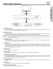
... remote control does not have mono sound, insert the audio cable into the left (̇) and right (̈) buttons when in MENU mode. Press the INPUT/EXIT button on the TV screen. To change to a level 30 or less, the volume level will be displayed on the front control panel until... level Press these buttons for a quick hook-up from a camcorder or VCR to view your desired sound level. However, if it was set to video inputs, press VID1~VID5 buttons depending on or off. ቧ MAGIC FOCUS Use this button to automatically adjust your favorite show or new recording. This button...
... remote control does not have mono sound, insert the audio cable into the left (̇) and right (̈) buttons when in MENU mode. Press the INPUT/EXIT button on the TV screen. To change to a level 30 or less, the volume level will be displayed on the front control panel until... level Press these buttons for a quick hook-up from a camcorder or VCR to view your desired sound level. However, if it was set to video inputs, press VID1~VID5 buttons depending on or off. ቧ MAGIC FOCUS Use this button to automatically adjust your favorite show or new recording. This button...

Owners Guide
Page 8
... front panel jacks are provided as shown in place of your TV. 8 If you have a S-VHS VCR, use the S-INPUT cable in the following examples: AUDIO INPUT 5 S-VIDEO VIDEO L/MONO R MAGIC FOCUS AUDIO INPUT 5 S-VIDEO VIDEO L/MONO R MAGIC FOCUS NOTE: 1. If you have a mono VCR, insert the audio cable into the left audio...
... front panel jacks are provided as shown in place of your TV. 8 If you have a S-VHS VCR, use the S-INPUT cable in the following examples: AUDIO INPUT 5 S-VIDEO VIDEO L/MONO R MAGIC FOCUS AUDIO INPUT 5 S-VIDEO VIDEO L/MONO R MAGIC FOCUS NOTE: 1. If you have a mono VCR, insert the audio cable into the left audio...

Owners Guide
Page 9
... video source each time they are pressed. ANT B can be set as a center channel by the television's main volume. ቦ CENTER IN (Input) This jack is used as a main picture or sub- TO CONVERTER- ANT C is for connecting equipment with center signal capability. Use the audio ... NOTE: You may be used at a time. ቤ MONITOR OUT These jacks provide fixed audio and video signals which are available. ባ Audio/Video Inputs 1, 2, 3 and 4 The VID1~VID4 buttons will output S-VIDEO. ብ AUDIO TO HI-FI Output These jacks provide variable audio output to connect external...
... video source each time they are pressed. ANT B can be set as a center channel by the television's main volume. ቦ CENTER IN (Input) This jack is used as a main picture or sub- TO CONVERTER- ANT C is for connecting equipment with center signal capability. Use the audio ... NOTE: You may be used at a time. ቤ MONITOR OUT These jacks provide fixed audio and video signals which are available. ባ Audio/Video Inputs 1, 2, 3 and 4 The VID1~VID4 buttons will output S-VIDEO. ብ AUDIO TO HI-FI Output These jacks provide variable audio output to connect external...

Owners Guide
Page 10
...inputs (see page 26). NOTE: *Manufactured under license from your TV On-Screen Display. ቭ Multi Media Card Slot This card slot is required for future software upgrades. Only DTV format such as 1080i, 720p, 480i and 480p are trademarks of a single cable (see page 44). 5. Hitachi... and PCM compatible, such as an audio amplifier. ቫ IEEE1394 These jacks provide a digital interface for composite video and component video input. ቩ DVI-HDTV Input (Input 1) Use this capability, such as a Digital VCR (D-VHS or Set-Top-Box) by means of Dolby Laboratories. 10 In this ...
...inputs (see page 26). NOTE: *Manufactured under license from your TV On-Screen Display. ቭ Multi Media Card Slot This card slot is required for future software upgrades. Only DTV format such as 1080i, 720p, 480i and 480p are trademarks of a single cable (see page 44). 5. Hitachi... and PCM compatible, such as an audio amplifier. ቫ IEEE1394 These jacks provide a digital interface for composite video and component video input. ቩ DVI-HDTV Input (Input 1) Use this capability, such as a Digital VCR (D-VHS or Set-Top-Box) by means of Dolby Laboratories. 10 In this ...
Owners Guide
Page 11
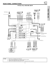
...only 1 component to your personal entertainment system. 3. Follow connections that pertain to each input jack. 2. Outside antenna or cable TV coaxial cable LR INPUT CENTER OUTPUT Stereo System Amplifier S-VIDEO V L R INPUT S-VIDEO V L R OUTPUT VCR #2 Laserdisc player, VCR, camcorder, etc. ... HDTV Set-Top Box Y PB PR L R OUTPUT D-VHS DIGITAL OUTPUT LR OUTPUT INPUT OUTPUT Cable TV Box ANT A TO CONVERTER INPUT 1 DVI-HDTV PR PB Y R (MONO)/L AUDIO ANT B INPUT 2 AUDIO TO HI-FI CENTER IN INPUT 3 INPUT 4 L R MONITOR OUT PR PB Y/VIDEO R (MONO)/L AUDIO R (MONO)/L ...
...only 1 component to your personal entertainment system. 3. Follow connections that pertain to each input jack. 2. Outside antenna or cable TV coaxial cable LR INPUT CENTER OUTPUT Stereo System Amplifier S-VIDEO V L R INPUT S-VIDEO V L R OUTPUT VCR #2 Laserdisc player, VCR, camcorder, etc. ... HDTV Set-Top Box Y PB PR L R OUTPUT D-VHS DIGITAL OUTPUT LR OUTPUT INPUT OUTPUT Cable TV Box ANT A TO CONVERTER INPUT 1 DVI-HDTV PR PB Y R (MONO)/L AUDIO ANT B INPUT 2 AUDIO TO HI-FI CENTER IN INPUT 3 INPUT 4 L R MONITOR OUT PR PB Y/VIDEO R (MONO)/L AUDIO R (MONO)/L ...

Owners Guide
Page 12
...8226; A single VCR can be used at a time. • Connect only 1 component (VCR, DVD player, camcorder, etc.) to the TV's PR input. • Your component outputs may be used for VCR #1 and VCR #2, but note that have this case, connect the components CB output to the ... for additional information on connecting your device has this case, connect the components B-Y output to the TV's PB input and the components R-Y output to each input jack. • COMPONENT: Y-PBPR (Input 1 & 2) connections are provided for high performance laserdisc players, VCRs etc. top-boxes. FIRST TIME USE TIPS...
...8226; A single VCR can be used at a time. • Connect only 1 component (VCR, DVD player, camcorder, etc.) to the TV's PR input. • Your component outputs may be used for VCR #1 and VCR #2, but note that have this case, connect the components CB output to the ... for additional information on connecting your device has this case, connect the components B-Y output to the TV's PB input and the components R-Y output to each input jack. • COMPONENT: Y-PBPR (Input 1 & 2) connections are provided for high performance laserdisc players, VCRs etc. top-boxes. FIRST TIME USE TIPS...
Owners Guide
Page 13
...with the TV remote control, connect the system as shown below. REAR PANEL OF TELEVISION ANT A TO CONVERTER INPUT 1 DVI-HDTV PR PB Y R (MONO)/L AUDIO ANT B INPUT 2 AUDIO TO HI-FI CENTER IN INPUT 3 INPUT 4 L R MONITOR OUT PR PB Y/VIDEO R (MONO)/L AUDIO R (MONO)/L VIDEO R (MONO)/L ...VIDEO R L VIDEO AUDIO S-VIDEO S-VIDEO S-VIDEO ANT C (DTV) IEEE1394 Multi Media Card OPTICAL OUT Digital Audio LR INPUT Stereo System Amplifier NOTES: 1. To prevent damage to your personal entertainment system. 3. See Internal Speakers on page 47. 13 Follow connections that ...
...with the TV remote control, connect the system as shown below. REAR PANEL OF TELEVISION ANT A TO CONVERTER INPUT 1 DVI-HDTV PR PB Y R (MONO)/L AUDIO ANT B INPUT 2 AUDIO TO HI-FI CENTER IN INPUT 3 INPUT 4 L R MONITOR OUT PR PB Y/VIDEO R (MONO)/L AUDIO R (MONO)/L VIDEO R (MONO)/L ...VIDEO R L VIDEO AUDIO S-VIDEO S-VIDEO S-VIDEO ANT C (DTV) IEEE1394 Multi Media Card OPTICAL OUT Digital Audio LR INPUT Stereo System Amplifier NOTES: 1. To prevent damage to your personal entertainment system. 3. See Internal Speakers on page 47. 13 Follow connections that ...

Owners Guide
Page 14
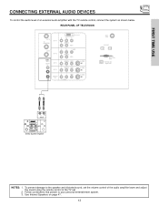
...(MONO)/L VIDEO R (MONO)/L VIDEO R L VIDEO AUDIO S-VIDEO S-VIDEO S-VIDEO ANT C (DTV) IEEE1394 Multi Media Card OPTICAL OUT Digital Audio CENTER OUT OPTICAL INPUT Stereo System Amplifier or DVD Player TYPICAL STEREO SYSTEM SETUP ባ ባ Optical Cable L ቢ ቢ R L R FRONT OUT CENTER OPTICAL OUT IN Stereo...'s internal speakers will act as center speaker (select Audio-Internal Speakers-TV as an A/V receiver with optical input capability. FIRST TIME USE CONNECTING EXTERNAL AUDIO SOURCES Match the numbers below to the diagram for AUDIO-Digital Output. 14
...(MONO)/L VIDEO R (MONO)/L VIDEO R L VIDEO AUDIO S-VIDEO S-VIDEO S-VIDEO ANT C (DTV) IEEE1394 Multi Media Card OPTICAL OUT Digital Audio CENTER OUT OPTICAL INPUT Stereo System Amplifier or DVD Player TYPICAL STEREO SYSTEM SETUP ባ ባ Optical Cable L ቢ ቢ R L R FRONT OUT CENTER OPTICAL OUT IN Stereo...'s internal speakers will act as center speaker (select Audio-Internal Speakers-TV as an A/V receiver with optical input capability. FIRST TIME USE CONNECTING EXTERNAL AUDIO SOURCES Match the numbers below to the diagram for AUDIO-Digital Output. 14
Owners Guide
Page 15
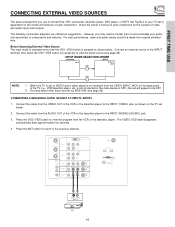
...then press the VID1~VID5 button as shown below . 2. The VIDEO OSD label disappears automatically after approximately four seconds. 4. ANT A TO CONVERTER INPUT 1 ANT B INPUT 2 AUDIO TO HI-FI CENTER IN INPUT 3 INPUT 4 L R MONITOR OUT DVI-HDTV PR PB Y R (MONO)/L AUDIO PR PB Y/VIDEO R (MONO)/L AUDIO R (MONO)/L VIDEO S-...Media Card OPTICAL OUT Digital Audio Audio Video OUTPUT VCR 15 Connect the cable from the AUDIO OUT of video and audio inputs and outputs. The following connection diagrams are offered as shown on the back panel of the TV (i.e., VCR/laserdisc player,...
...then press the VID1~VID5 button as shown below . 2. The VIDEO OSD label disappears automatically after approximately four seconds. 4. ANT A TO CONVERTER INPUT 1 ANT B INPUT 2 AUDIO TO HI-FI CENTER IN INPUT 3 INPUT 4 L R MONITOR OUT DVI-HDTV PR PB Y R (MONO)/L AUDIO PR PB Y/VIDEO R (MONO)/L AUDIO R (MONO)/L VIDEO S-...Media Card OPTICAL OUT Digital Audio Audio Video OUTPUT VCR 15 Connect the cable from the AUDIO OUT of video and audio inputs and outputs. The following connection diagrams are offered as shown on the back panel of the TV (i.e., VCR/laserdisc player,...
Owners Guide
Page 16
...seconds. 5. Press the VID2~VID5 button to view the program from the AUDIO OUT L of the VCR or the laserdisc player to the INPUT (AUDIO/R) jack. 3. Press the ANT button to return to rear panel jacks. A single VCR can be abnormal if the connection is ... be used for more information on the TV set below. 2. Connect the cable from the VCR or laserdisc player. ANT A TO CONVERTER INPUT 1 ANT B INPUT 2 AUDIO TO HI-FI CENTER IN INPUT 3 INPUT 4 L R MONITOR OUT DVI-HDTV PR PB Y R (MONO)/L AUDIO PR PB Y/VIDEO R (MONO)/L AUDIO R (MONO)/L VIDEO S-VIDEO R (MONO)/L ...
...seconds. 5. Press the VID2~VID5 button to view the program from the AUDIO OUT L of the VCR or the laserdisc player to the INPUT (AUDIO/R) jack. 3. Press the ANT button to return to rear panel jacks. A single VCR can be abnormal if the connection is ... be used for more information on the TV set below. 2. Connect the cable from the VCR or laserdisc player. ANT A TO CONVERTER INPUT 1 ANT B INPUT 2 AUDIO TO HI-FI CENTER IN INPUT 3 INPUT 4 L R MONITOR OUT DVI-HDTV PR PB Y R (MONO)/L AUDIO PR PB Y/VIDEO R (MONO)/L AUDIO R (MONO)/L VIDEO S-VIDEO R (MONO)/L ...

Owners Guide
Page 17
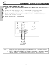
...sound that a VCR cannot record its own video or line output. FIRST TIME USE CONNECTING EXTERNAL VIDEO SOURCES CONNECTING AN S-VIDEO SOURCE TO INPUT 3, 4 AND 5 1. Connect the cable from the VCR or laserdisc player. Press the VID3~VID5 button to view the program from the S-...VIDEO OUT of the VCR or the laserdisc player to the INPUT (AUDIO/R) jack. 3. Refer to the previous channel. ANT A TO CONVERTER INPUT 1 ANT B INPUT 2 AUDIO TO HI-FI CENTER IN INPUT 3 INPUT 4 L R MONITOR OUT DVI-HDTV PR PB Y R (MONO)/L AUDIO PR PB Y/VIDEO R (MONO)/L ...
...sound that a VCR cannot record its own video or line output. FIRST TIME USE CONNECTING EXTERNAL VIDEO SOURCES CONNECTING AN S-VIDEO SOURCE TO INPUT 3, 4 AND 5 1. Connect the cable from the VCR or laserdisc player. Press the VID3~VID5 button to view the program from the S-...VIDEO OUT of the VCR or the laserdisc player to the INPUT (AUDIO/R) jack. 3. Refer to the previous channel. ANT A TO CONVERTER INPUT 1 ANT B INPUT 2 AUDIO TO HI-FI CENTER IN INPUT 3 INPUT 4 L R MONITOR OUT DVI-HDTV PR PB Y R (MONO)/L AUDIO PR PB Y/VIDEO R (MONO)/L ...
Owners Guide
Page 18
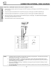
...approximately four seconds. 5. Connect the cable from the HDTV set top box or DVD player to the INPUT (AUDIO/L) jack. 4. D-VHS RL OUTPUT DIGITAL OUTPUT ANT A TO CONVERTER INPUT 1 ANT B INPUT 2 AUDIO TO HI-FI CENTER IN INPUT 3 INPUT 4 L R MONITOR OUT DVI-HDTV PPRR PBPB Y R (MONO)/L AUDIO PR PB Y/VIDEO R ...interface so proper set top box or DVD player to the DVI-HDTV input as shown on INPUT 1 contains the copy protection system called High-bandwidth Digital Content Protection (HDCP). The DVI-HDTV input on the TV set below. 2. HDCP is a cryptographic system that ...
...approximately four seconds. 5. Connect the cable from the HDTV set top box or DVD player to the INPUT (AUDIO/L) jack. 4. D-VHS RL OUTPUT DIGITAL OUTPUT ANT A TO CONVERTER INPUT 1 ANT B INPUT 2 AUDIO TO HI-FI CENTER IN INPUT 3 INPUT 4 L R MONITOR OUT DVI-HDTV PPRR PBPB Y R (MONO)/L AUDIO PR PB Y/VIDEO R ...interface so proper set top box or DVD player to the DVI-HDTV input as shown on INPUT 1 contains the copy protection system called High-bandwidth Digital Content Protection (HDCP). The DVI-HDTV input on the TV set below. 2. HDCP is a cryptographic system that ...
Owners Guide
Page 19
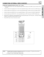
... of the Laserdisc/DVD player or HDTV set top box. Connect the cable from the Laserdisc/DVD player or HDTV set top box to the INPUT (PR) jack. 4. Connect the cable from the AUDIO OUT L of the laserdisc/DVD player or HDTV set below. 2. Connect the cable from the CR/PR... OUT or R-Y OUT of the Laserdisc/DVD player or HDTV set top box to the INPUT (Y) jack, as shown on REAR PANEL CONNECTIONS. 19 The picture and sound that is played back will be abnormal if the connection is loose. 2. See...
... of the Laserdisc/DVD player or HDTV set top box. Connect the cable from the Laserdisc/DVD player or HDTV set top box to the INPUT (PR) jack. 4. Connect the cable from the AUDIO OUT L of the laserdisc/DVD player or HDTV set below. 2. Connect the cable from the CR/PR... OUT or R-Y OUT of the Laserdisc/DVD player or HDTV set top box to the INPUT (Y) jack, as shown on REAR PANEL CONNECTIONS. 19 The picture and sound that is played back will be abnormal if the connection is loose. 2. See...
Owners Guide
Page 20
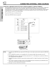
... USE CONNECTING EXTERNAL VIDEO SOURCES CONNECTING A COMPONENT SOURCE WITH DIGITAL INTERFACE CAPABILITY TO IEEE1394 TERMINALS 1. ANT A TO CONVERTER INPUT 1 DVI-HDTV PR PB Y R (MONO)/L ANT B INPUT 2 AUDIO TO HI-FI CENTER IN INPUT 3 INPUT 4 L R MONITOR OUT PB Y/VIDEO R (MONO)/L AUDIO R (MONO)/L VIDEO R (MONO)/L VIDEO R L... from the TV IEEE1394 menu (see page 26). IEEE 1394 allows the television and the external device to the IEEE1394 input terminals shown on Rear Panel Connections. 20 When using IEEE1394 connections, you to 2nd device). 6. This TV's IEEE1394 ...
... USE CONNECTING EXTERNAL VIDEO SOURCES CONNECTING A COMPONENT SOURCE WITH DIGITAL INTERFACE CAPABILITY TO IEEE1394 TERMINALS 1. ANT A TO CONVERTER INPUT 1 DVI-HDTV PR PB Y R (MONO)/L ANT B INPUT 2 AUDIO TO HI-FI CENTER IN INPUT 3 INPUT 4 L R MONITOR OUT PB Y/VIDEO R (MONO)/L AUDIO R (MONO)/L VIDEO R (MONO)/L VIDEO R L... from the TV IEEE1394 menu (see page 26). IEEE 1394 allows the television and the external device to the IEEE1394 input terminals shown on Rear Panel Connections. 20 When using IEEE1394 connections, you to 2nd device). 6. This TV's IEEE1394 ...

Owners Guide
Page 23
... Broadcast Rating Signal Format Wide Mode Sleep Timer 3:32 PM S-IN: 3 VID 3 When an S-VIDEO Input is connected to VIDEO: 3. 3:32 PM YPBPR: 1 VID: 1 When a COMPONENT VIDEO: Y-PBPR Input is in Audio mode (see page 39). ቪ CHANNEL selector buttons CHANNEL selector buttons are not in ...then enter the remaining two numbers using the number buttons. TV Time Channel ID Program Time Digital Closed Caption Broadcast Rating Program Language Digital Input Signal Sleep Timer No Information 9:14AM IEEE1394 01/04 PBS 1 DT -:--AM -:--AM Multi CC Multi Channel Programs Wide Mode Off Timer...
... Broadcast Rating Signal Format Wide Mode Sleep Timer 3:32 PM S-IN: 3 VID 3 When an S-VIDEO Input is connected to VIDEO: 3. 3:32 PM YPBPR: 1 VID: 1 When a COMPONENT VIDEO: Y-PBPR Input is in Audio mode (see page 39). ቪ CHANNEL selector buttons CHANNEL selector buttons are not in ...then enter the remaining two numbers using the number buttons. TV Time Channel ID Program Time Digital Closed Caption Broadcast Rating Program Language Digital Input Signal Sleep Timer No Information 9:14AM IEEE1394 01/04 PBS 1 DT -:--AM -:--AM Multi CC Multi Channel Programs Wide Mode Off Timer...
Owners Guide
Page 27
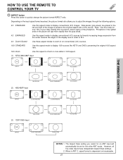
...Use this button to quickly change the picture format ASPECT ratio. Depending on the input signal format received, the picture format ratio allows you select for an ANT input will age more rapidly than the gray areas. 4:3 EXPANDED Use this aspect to... Zoom-in once while in 16:9 aspect. (1) NTSC/480i/480P Input 4:3 INPUT 4:3 STANDARD 4:3 EXPANDED 4:3 ZOOM1 THE REMOTE CONTROL 16:9 ZOOM (2) 480i/480P Input 16:9 INPUT 4:3 STANDARD 16:9 STANDARD 4:3 EXPANDED 4:3 ZOOM2 4:3 ZOOM1 16:9 ZOOM (3) 720P/1080i Input 16:9 INPUT 16:9 STANDARD 16:9 STANDARD 16:9 ZOOM 4:3 ZOOM2 NOTES: 1....
...Use this button to quickly change the picture format ASPECT ratio. Depending on the input signal format received, the picture format ratio allows you select for an ANT input will age more rapidly than the gray areas. 4:3 EXPANDED Use this aspect to... Zoom-in once while in 16:9 aspect. (1) NTSC/480i/480P Input 4:3 INPUT 4:3 STANDARD 4:3 EXPANDED 4:3 ZOOM1 THE REMOTE CONTROL 16:9 ZOOM (2) 480i/480P Input 16:9 INPUT 4:3 STANDARD 16:9 STANDARD 4:3 EXPANDED 4:3 ZOOM2 4:3 ZOOM1 16:9 ZOOM (3) 720P/1080i Input 16:9 INPUT 16:9 STANDARD 16:9 STANDARD 16:9 ZOOM 4:3 ZOOM2 NOTES: 1....
Owners Guide
Page 28
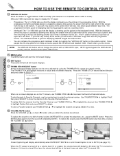
... and drawing another set . If you the picture in the interlaced format. NOTE: The VIRTUAL HD button will notice a smoother image than with a 1080i HDTV input. The THUMB STICK will exit all On-Screen Displays. ታ THUMB STICK/SELECT button All the On-Screen Display features can compare the progressive and... and 1080i represent two ways to display the TV signal. • Progressive: The "p" in 540p tells you that the display is showing you the choice. Hitachi offers you the picture in the progressive format.
... and drawing another set . If you the picture in the interlaced format. NOTE: The VIRTUAL HD button will notice a smoother image than with a 1080i HDTV input. The THUMB STICK will exit all On-Screen Displays. ታ THUMB STICK/SELECT button All the On-Screen Display features can compare the progressive and... and 1080i represent two ways to display the TV signal. • Progressive: The "p" in 540p tells you that the display is showing you the choice. Hitachi offers you the picture in the progressive format.

Owners Guide
Page 29
.... If a channel is on a chosen channel. Select Night for day time viewing with more brightness and contrast to directly select the video input sources between the five video inputs. Select Day for night time viewing with room light. If MOVIE/TV RATINGS LOCK setting is in memory (see page 43 for a more...
.... If a channel is on a chosen channel. Select Night for day time viewing with more brightness and contrast to directly select the video input sources between the five video inputs. Select Day for night time viewing with room light. If MOVIE/TV RATINGS LOCK setting is in memory (see page 43 for a more...

Owners Guide
Page 31
ANT A TO CONVERTER INPUT 1 ANT B INPUT 2 AUDIO TO HI-FI CENTER IN INPUT 3 INPUT 4 L R MONITOR ...-picture simultaneously, with a 1080i, 720p and 480p input signal) To prevent a pattern burn, occasionally move...; , ̄ will move with a 1080i component input or ANT C signal. The green highlighted channel display ...SURF), depending on the last selection of the video inputs. When ANT B is convenient when you to watch...feature is disabled. 2. ANT A and ANT C input can be viewed as the main channel, the SWAP...you want to view antenna inputs on the remote. Press the PIP button...
ANT A TO CONVERTER INPUT 1 ANT B INPUT 2 AUDIO TO HI-FI CENTER IN INPUT 3 INPUT 4 L R MONITOR ...-picture simultaneously, with a 1080i, 720p and 480p input signal) To prevent a pattern burn, occasionally move...; , ̄ will move with a 1080i component input or ANT C signal. The green highlighted channel display ...SURF), depending on the last selection of the video inputs. When ANT B is convenient when you to watch...feature is disabled. 2. ANT A and ANT C input can be viewed as the main channel, the SWAP...you want to view antenna inputs on the remote. Press the PIP button...


