
Owners Guide
Page 2
... 15.122 of the television. NOTE: • There are no user serviceable parts inside the television. • Model and serial numbers are not expressly approved by HITACHI could void the user's authority to notify you . CAUTION: Adjust only those controls that a safety problem should be of a sufficient magnitude to persons. REFER SERVICING TO QUALIFIED SERVICE PERSONNEL. NOTE: This television receiver will enable HITACHI to operate the television. CAUTION RISK OF...
... 15.122 of the television. NOTE: • There are no user serviceable parts inside the television. • Model and serial numbers are not expressly approved by HITACHI could void the user's authority to notify you . CAUTION: Adjust only those controls that a safety problem should be of a sufficient magnitude to persons. REFER SERVICING TO QUALIFIED SERVICE PERSONNEL. NOTE: This television receiver will enable HITACHI to operate the television. CAUTION RISK OF...
Owners Guide
Page 3
... HITACHI Factory Warranty. • PUBLIC VIEWING OF COPYRIGHTED MATERIAL Public viewing of receiving analog basic, digital basic and digital premium cable television programming by the man- Unplug this product in any objects on -screen displays such as to overturn resulting in wide screen format or zoomed to fit the screen with applicable environmental laws. ANTENNA LEAD IN WIRE GROUND CLAMP ELECTRIC SERVICE EQUIPMENT NEC NATIONAL ELECTRICAL CODE ANTENNA...
... HITACHI Factory Warranty. • PUBLIC VIEWING OF COPYRIGHTED MATERIAL Public viewing of receiving analog basic, digital basic and digital premium cable television programming by the man- Unplug this product in any objects on -screen displays such as to overturn resulting in wide screen format or zoomed to fit the screen with applicable environmental laws. ANTENNA LEAD IN WIRE GROUND CLAMP ELECTRIC SERVICE EQUIPMENT NEC NATIONAL ELECTRICAL CODE ANTENNA...
Owners Guide
Page 5
... color changes, and increased chance of set . Picture brightness decreases as close to the television. During daylight hours, reflections from the perforated back cover of the receiver. Also, be used to reduce the reflection or the TV can become excessively hot, for best performance. If so, drapes or screens can be sure that is free from the television until there is no picture distortion. 5 The sound of the HITACHI Projection Television...
... color changes, and increased chance of set . Picture brightness decreases as close to the television. During daylight hours, reflections from the perforated back cover of the receiver. Also, be used to reduce the reflection or the TV can become excessively hot, for best performance. If so, drapes or screens can be sure that is free from the television until there is no picture distortion. 5 The sound of the HITACHI Projection Television...

Owners Guide
Page 7
... volume level will be tuned and viewed. The blinking time of the Power button LED varies depending on the period of this button to optimum performance (see page 64). ቧ MAGIC FOCUS Use this television. This is an additional remote sensor for your picture quality to automatically adjust your desired sound level. FRONT PANEL CONTROLS ቩ ቪ FIRST TIME USE ቦ INPUT 5 AUDIO S-VIDEO VIDEO L/MONO R ቨ ቦ VOL- When the TV power is turned OFF...
... volume level will be tuned and viewed. The blinking time of the Power button LED varies depending on the period of this button to optimum performance (see page 64). ቧ MAGIC FOCUS Use this television. This is an additional remote sensor for your picture quality to automatically adjust your desired sound level. FRONT PANEL CONTROLS ቩ ቪ FIRST TIME USE ቦ INPUT 5 AUDIO S-VIDEO VIDEO L/MONO R ቨ ቦ VOL- When the TV power is turned OFF...

Owners Guide
Page 9
... HDMI 1 VIDEO L AUDIO R AUDIO TO HI-FI PR PR (MONO) (MONO) (MONO) (MONO) TV AS CENTER OPTICAL OUT Digital Audio Upgrade Card Apparatus Claims of the remote control you have mono sound, insert the audio cable into the left audio jack.) NOTE: You may be abnormal, when using the Y-PBPR jacks. 6. A 75-Ohm RF antenna or CATV (Cable TV) input. ANT A can be displayed as a DVD player or Set Top Box. ANT B cannot be used for high quality video output...
... HDMI 1 VIDEO L AUDIO R AUDIO TO HI-FI PR PR (MONO) (MONO) (MONO) (MONO) TV AS CENTER OPTICAL OUT Digital Audio Upgrade Card Apparatus Claims of the remote control you have mono sound, insert the audio cable into the left audio jack.) NOTE: You may be abnormal, when using the Y-PBPR jacks. 6. A 75-Ohm RF antenna or CATV (Cable TV) input. ANT A can be displayed as a DVD player or Set Top Box. ANT B cannot be used for high quality video output...

Owners Guide
Page 11
... S-VIDEO INPUT 4 INPUT 3 INPUT 2 Y/ VIDEO PB INPUT 1 Y/ VIDEO PB VIDEO L AUDIO R AUDIO TO HI-FI (MONO) PR PR (MONO) (MONO) (MONO) TV AS CENTER CableCARD HDMIIN1SERT THIS END OPTICAL OUT Digital Audio Upgrade Card Apparatus Claims of the Rear Panel Jacks. CableCARD is installed OR CableCARD is not installed After the CableCARD is required. 2. Connect a coaxial cable to your cable operator and give them the information from the card to exit the second screen. NOTES: 1. FIRST TIME USE REAR PANEL...
... S-VIDEO INPUT 4 INPUT 3 INPUT 2 Y/ VIDEO PB INPUT 1 Y/ VIDEO PB VIDEO L AUDIO R AUDIO TO HI-FI (MONO) PR PR (MONO) (MONO) (MONO) TV AS CENTER CableCARD HDMIIN1SERT THIS END OPTICAL OUT Digital Audio Upgrade Card Apparatus Claims of the Rear Panel Jacks. CableCARD is installed OR CableCARD is not installed After the CableCARD is required. 2. Connect a coaxial cable to your cable operator and give them the information from the card to exit the second screen. NOTES: 1. FIRST TIME USE REAR PANEL...

Owners Guide
Page 13
... be used at a time. • Connect only 1 component (VCR, DVD player, camcorder, etc.) to obtain optimum picture quality when using the Y-PBPR inputs (see page 37). • To ensure no copyright infringement, the MONITOR OUT output may be abnormal, when using the Y-PBPR jacks. • When using an HDMI input from a Set-Top-Box, it to the left audio jack on the television. • Refer to the TV's PR input...
... be used at a time. • Connect only 1 component (VCR, DVD player, camcorder, etc.) to obtain optimum picture quality when using the Y-PBPR inputs (see page 37). • To ensure no copyright infringement, the MONITOR OUT output may be abnormal, when using the Y-PBPR jacks. • When using an HDMI input from a Set-Top-Box, it to the left audio jack on the television. • Refer to the TV's PR input...
Owners Guide
Page 15
... the INPUT (VIDEO) jack, as suggestions. RS232C 1 2 345 6 789 Audio Video OUTPUT VCR 15 However, you use to connect the VCR, camcorder, laserdisc player, DVD player, or HDTV Set Top Box to your TV set to VIDEO and a video signal is not received from the VIDEO INPUT JACK on the back panel of the TV (i.e., VCR/laserdisc player, etc. Connect the cable from the VCR or the laserdisc player. Press the INPUTS button, then select INPUT 1 from the INPUTS menu to view the program...
... the INPUT (VIDEO) jack, as suggestions. RS232C 1 2 345 6 789 Audio Video OUTPUT VCR 15 However, you use to connect the VCR, camcorder, laserdisc player, DVD player, or HDTV Set Top Box to your TV set to VIDEO and a video signal is not received from the VIDEO INPUT JACK on the back panel of the TV (i.e., VCR/laserdisc player, etc. Connect the cable from the VCR or the laserdisc player. Press the INPUTS button, then select INPUT 1 from the INPUTS menu to view the program...

Owners Guide
Page 16
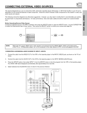
... a VCR cannot record its own video or line output. Connect the cable from the INPUTS menu to your VCR operating guide for limited viewing uses only. Press the INPUTS button, then select INPUT 3 from the AUDIO OUT R of U.S. Refer to view the program from the INPUTS menu to return to the previous channel. FIRST TIME USE CONNECTING EXTERNAL VIDEO SOURCES CONNECTING A STEREO SOURCE TO INPUT1~INPUT5 1. Select Antenna from the VCR or laserdisc player. A single VCR can be...
... a VCR cannot record its own video or line output. Connect the cable from the INPUTS menu to your VCR operating guide for limited viewing uses only. Press the INPUTS button, then select INPUT 3 from the AUDIO OUT R of U.S. Refer to view the program from the INPUTS menu to return to the previous channel. FIRST TIME USE CONNECTING EXTERNAL VIDEO SOURCES CONNECTING A STEREO SOURCE TO INPUT1~INPUT5 1. Select Antenna from the VCR or laserdisc player. A single VCR can be...

Owners Guide
Page 18
... the INPUTS button, then select INPUT 1 from the output of U.S. The HDMI input on the TV set top box or DVD player to HDMI connection cable from the INPUTS menu to the previous channel. HDMI is loose. 2. RS232C 1 2 345 6 789 HDMI Cable HDMI Output DVD Player or HDTV STB ANT B MONITOR OUT S-VIDEO INPUT 4 INPUT 3 INPUT 2 Y/ VIDEO PB INPUT 1 Y/ VIDEO PB HDMI 1 VIDEO L AUDIO R AUDIO TO HI-FI PR PR (MONO) (MONO) (MONO) (MONO) TV AS CENTER OPTICAL OUT Digital Audio Upgrade Card Apparatus Claims of the HDTV set below. Connect the HDMI or DVI to the HDMI input as...
... the INPUTS button, then select INPUT 1 from the output of U.S. The HDMI input on the TV set top box or DVD player to HDMI connection cable from the INPUTS menu to the previous channel. HDMI is loose. 2. RS232C 1 2 345 6 789 HDMI Cable HDMI Output DVD Player or HDTV STB ANT B MONITOR OUT S-VIDEO INPUT 4 INPUT 3 INPUT 2 Y/ VIDEO PB INPUT 1 Y/ VIDEO PB HDMI 1 VIDEO L AUDIO R AUDIO TO HI-FI PR PR (MONO) (MONO) (MONO) (MONO) TV AS CENTER OPTICAL OUT Digital Audio Upgrade Card Apparatus Claims of the HDTV set below. Connect the HDMI or DVI to the HDMI input as...

Owners Guide
Page 19
... 6 789 OUTPUT R L PR PB Y DVD Player NOTES: 1. Select Antenna from the CB/PB OUT or B-Y OUT of the Laserdisc/DVD player or HDTV set top box. Patent Nos. 4,631,603; 4,577,216; 4,819,098; 4,907,093; Connect the cable from the INPUTS menu to return to rear panel jacks. The picture and sound that is played back will be abnormal if the connection is loose. 2. FIRST TIME USE CONNECTING EXTERNAL VIDEO SOURCES CONNECTING A COMPONENT...
... 6 789 OUTPUT R L PR PB Y DVD Player NOTES: 1. Select Antenna from the CB/PB OUT or B-Y OUT of the Laserdisc/DVD player or HDTV set top box. Patent Nos. 4,631,603; 4,577,216; 4,819,098; 4,907,093; Connect the cable from the INPUTS menu to return to rear panel jacks. The picture and sound that is played back will be abnormal if the connection is loose. 2. FIRST TIME USE CONNECTING EXTERNAL VIDEO SOURCES CONNECTING A COMPONENT...
Owners Guide
Page 26
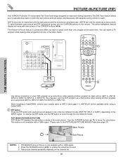
... A ANT B MONITOR OUT S-VIDEO INPUT 4 INPUT 3 INPUT 2 Y/ VIDEO PB INPUT 1 Y/ VIDEO PB HDMI 1 VIDEO L AUDIO R AUDIO TO HI-FI PR PR (MONO) (MONO) (MONO) (MONO) TV AS CENTER CableCARD (Top of card faces right) OPTICAL OUT Digital Audio Upgrade Card Apparatus Claims of the main picture. You may also view the VCR program as a main picture while viewing another program as a sub-picture (ANT A, INPUT:2, INPUT:3, INPUT:4 or INPUT:5). POP MODE PICTURE-IN-PICTURE POP Mode PIP displays the sub-picture outside of U.S. The white highlighted channel display will move...
... A ANT B MONITOR OUT S-VIDEO INPUT 4 INPUT 3 INPUT 2 Y/ VIDEO PB INPUT 1 Y/ VIDEO PB HDMI 1 VIDEO L AUDIO R AUDIO TO HI-FI PR PR (MONO) (MONO) (MONO) (MONO) TV AS CENTER CableCARD (Top of card faces right) OPTICAL OUT Digital Audio Upgrade Card Apparatus Claims of the main picture. You may also view the VCR program as a main picture while viewing another program as a sub-picture (ANT A, INPUT:2, INPUT:3, INPUT:4 or INPUT:5). POP MODE PICTURE-IN-PICTURE POP Mode PIP displays the sub-picture outside of U.S. The white highlighted channel display will move...
Owners Guide
Page 30
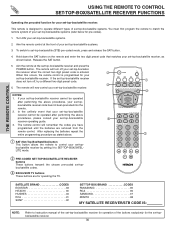
... first program the remote to SET-TOP-BOX/SATEL- If your set-top-box/satellite receiver cannot be operated after performing the above procedures, please consult your set -top-box/satellite systems. 3. This remote is programmed for pre-codes). 1. The remote control will turn off your set -top-box/satellite receiver for operation of set -top-box/satellite receiver. ባ NOTES: 1. To switch to instruction manual of your set -topbox/satellite codes. ቤ EXCLUSIVE TV buttons These buttons are removed from the remote control. Turn...
... first program the remote to SET-TOP-BOX/SATEL- If your set-top-box/satellite receiver cannot be operated after performing the above procedures, please consult your set -top-box/satellite systems. 3. This remote is programmed for pre-codes). 1. The remote control will turn off your set -top-box/satellite receiver for operation of set -top-box/satellite receiver. ባ NOTES: 1. To switch to instruction manual of your set -topbox/satellite codes. ቤ EXCLUSIVE TV buttons These buttons are removed from the remote control. Turn...

Owners Guide
Page 35
... Scan mode. Feature to upgrade TV software. Set Monitor Out source. Block various types of the Channel Manager OSD is installed in standard mode. Label Video Inputs , VCR, DVD, etc. Information display for Digital signals. 2. Select the TV Quick Start Up options. Choose English, French, or Spanish text. ON-SCREEN DISPLAY 35 Select to display dialogue/text. Change Lock access code. Block various types of the red, green and blue colors to Lock TV. Set specific time to make white. Set viewing reservation for TV programs. Automatic and manual...
... Scan mode. Feature to upgrade TV software. Set Monitor Out source. Block various types of the Channel Manager OSD is installed in standard mode. Label Video Inputs , VCR, DVD, etc. Information display for Digital signals. 2. Select the TV Quick Start Up options. Choose English, French, or Spanish text. ON-SCREEN DISPLAY 35 Select to display dialogue/text. Change Lock access code. Block various types of the red, green and blue colors to Lock TV. Set specific time to make white. Set viewing reservation for TV programs. Automatic and manual...

Owners Guide
Page 38
... video program being viewed. Video Picture Mode Contrast Brightness Color Tint Sharpness Color Temperature Black Enhancement Edge Enhancement Reset Video Settings Move SEL Select ANT A/B Day 100% 50% 50% 50% High Middle High Night Video Reset Video Settings Select "Reset" to return the video menu settings on the user's preference. Use the CURSOR button ̄ to highlight function. If RESET is not checked , the listed colors will reset to make them either deeper or more pure depending on this function to adjust...
... video program being viewed. Video Picture Mode Contrast Brightness Color Tint Sharpness Color Temperature Black Enhancement Edge Enhancement Reset Video Settings Move SEL Select ANT A/B Day 100% 50% 50% 50% High Middle High Night Video Reset Video Settings Select "Reset" to return the video menu settings on the user's preference. Use the CURSOR button ̄ to highlight function. If RESET is not checked , the listed colors will reset to make them either deeper or more pure depending on this function to adjust...

Owners Guide
Page 46
... the Front Panel will be used in -Picture will also be blocked. When TV TIME LOCK is turned on, all video inputs and the picture and sound for channels 3, 4 will be viewed during that time period (Set clock first). Use CURSOR buttons ̆ or ̄ to enter the access code. Text appears on the screen to indicate that TV TIME LOCK is a four digit access code number. The code to enter the Locks feature is activated. 3. Manager Locks Timers Setup Move SEL...
... the Front Panel will be used in -Picture will also be blocked. When TV TIME LOCK is turned on, all video inputs and the picture and sound for channels 3, 4 will be viewed during that time period (Set clock first). Use CURSOR buttons ̆ or ̄ to enter the access code. Text appears on the screen to indicate that TV TIME LOCK is a four digit access code number. The code to enter the Locks feature is activated. 3. Manager Locks Timers Setup Move SEL...
Owners Guide
Page 55
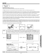
... UP from the Setup Menu. The output of time, the picture tubes can produce any time during self-adjust). The outputs of the red and blue tubes can be adjusted. Adjustment Mode Auto 9 Point Manual 117 Point Manual At turn off " is selected, the TV will not work when adjustment mode is set to produce the white lines. To simplify convergence, HITACHI incorporates a function called "convergence". If this button is called MAGIC FOCUS located on control panel will adjust itself after a time, you notice color rings or...
... UP from the Setup Menu. The output of time, the picture tubes can produce any time during self-adjust). The outputs of the red and blue tubes can be adjusted. Adjustment Mode Auto 9 Point Manual 117 Point Manual At turn off " is selected, the TV will not work when adjustment mode is set to produce the white lines. To simplify convergence, HITACHI incorporates a function called "convergence". If this button is called MAGIC FOCUS located on control panel will adjust itself after a time, you notice color rings or...

Owners Guide
Page 56
... to recall the factory pre-set convergence data. 56 ON-SCREEN DISPLAY If you use the Manual Adjustment Mode. 3. Manager Locks Timers Setup Move SEL Sel Setup Magic Focus Tune Up Menu Preference Set The Inputs Set Virtual HD Set Black Side Panel Set Closed Captions Set Monitor Out About Your TV Move SEL Select Setup Magic Focus Tune Up Aligns the Red, Green, and Blue colors to access menu mode. Video Audio Aspect Chan. To Adjust the Convergence Move the Adjustment Cursor to the point to be WHITE. SETUP Manual Convergence Adjustment Mode (9 Point Manual Adjustment) NOTES...
... to recall the factory pre-set convergence data. 56 ON-SCREEN DISPLAY If you use the Manual Adjustment Mode. 3. Manager Locks Timers Setup Move SEL Sel Setup Magic Focus Tune Up Menu Preference Set The Inputs Set Virtual HD Set Black Side Panel Set Closed Captions Set Monitor Out About Your TV Move SEL Select Setup Magic Focus Tune Up Aligns the Red, Green, and Blue colors to access menu mode. Video Audio Aspect Chan. To Adjust the Convergence Move the Adjustment Cursor to the point to be WHITE. SETUP Manual Convergence Adjustment Mode (9 Point Manual Adjustment) NOTES...

Owners Guide
Page 57
... manual convergence adjustment mode. Adjustment Mode Auto 9 Point Manual 117 Point Manual At turn ON your chosen option. Select CANCEL to cancel adjusted data and return to correct for at least 20 minutes before using the CURSOR buttons, the Adjustment Cursor must be erased. Video Audio Aspect Chan. Manager Locks Timers Setup Move SEL Sel Setup Magic Focus Tune Up Menu Preference Set The Inputs Set Virtual HD Set Black Side Panel Set Closed Captions Set Monitor Out About Your TV Move SEL Select ON-SCREEN DISPLAY Setup...
... manual convergence adjustment mode. Adjustment Mode Auto 9 Point Manual 117 Point Manual At turn ON your chosen option. Select CANCEL to cancel adjusted data and return to correct for at least 20 minutes before using the CURSOR buttons, the Adjustment Cursor must be erased. Video Audio Aspect Chan. Manager Locks Timers Setup Move SEL Sel Setup Magic Focus Tune Up Menu Preference Set The Inputs Set Virtual HD Set Black Side Panel Set Closed Captions Set Monitor Out About Your TV Move SEL Select ON-SCREEN DISPLAY Setup...
Owners Guide
Page 77
... Closed Captions Analog Captions 62 Digital Captions 62 Color Management 38 Color Decoding 39 Color Temperature 37 Color 37 Contrast 37 Convergence (see Magic Focus) D Date 51 Daylight Saving Correction 51 Disassembly/Assembly Instructions (57 71-73 Disassembly/Assembly Instructions (65 74-76 E Event Timer 53 F Freeze Button 21, 28 G Guide Button on Remote 24 H HDMI 10, 13, 18 I Input Setup 59 L Language Menu Language 58 Audio Language 42 Locks Change Access Code 46 Channel Lock 46 Input Lock 46 Front Panel Lock...
... Closed Captions Analog Captions 62 Digital Captions 62 Color Management 38 Color Decoding 39 Color Temperature 37 Color 37 Contrast 37 Convergence (see Magic Focus) D Date 51 Daylight Saving Correction 51 Disassembly/Assembly Instructions (57 71-73 Disassembly/Assembly Instructions (65 74-76 E Event Timer 53 F Freeze Button 21, 28 G Guide Button on Remote 24 H HDMI 10, 13, 18 I Input Setup 59 L Language Menu Language 58 Audio Language 42 Locks Change Access Code 46 Channel Lock 46 Input Lock 46 Front Panel Lock...


