
Owners Guide
Page 2
...important operating and maintenance (servicing) instructions in accordance with arrowhead symbol, within the product's enclosure that are not expressly approved by Hitachi could void the user's warranty. The exclamation point within an equilateral triangle, is designed to operate on back side of the ... RECEPTACLE, OR OTHER OUTLET UNLESS THE BLADES AND GROUND TERMINAL CAN BE FULLY INSERTED TO PREVENT BLADE EXPOSURE. NO USER SERVICEABLE PARTS INSIDE. REFER SERVICING TO QUALIFIED SERVICE PERSONNEL. WARNING: TO PREVENT FIRE OR SHOCK HAZARD, DO NOT EXPOSE THIS COLOR TELEVISION ...
...important operating and maintenance (servicing) instructions in accordance with arrowhead symbol, within the product's enclosure that are not expressly approved by Hitachi could void the user's warranty. The exclamation point within an equilateral triangle, is designed to operate on back side of the ... RECEPTACLE, OR OTHER OUTLET UNLESS THE BLADES AND GROUND TERMINAL CAN BE FULLY INSERTED TO PREVENT BLADE EXPOSURE. NO USER SERVICEABLE PARTS INSIDE. REFER SERVICING TO QUALIFIED SERVICE PERSONNEL. WARNING: TO PREVENT FIRE OR SHOCK HAZARD, DO NOT EXPOSE THIS COLOR TELEVISION ...

Owners Guide
Page 3
.... * Save these instructions for cleaning. Please fill out your television to dangerous voltage or other ). To help you to impact of HITACHI televisions. If you are unable to insert the plug fully into this television yourself as they may expose you operate these products properly,... this television set through the television cabinet's slots as opening or removing covers may touch dangerous voltage points or short out parts that a safety problem should still fail to fit, contact your electrician to traffic or abuse. Our reputation has been built on the...
.... * Save these instructions for cleaning. Please fill out your television to dangerous voltage or other ). To help you to impact of HITACHI televisions. If you are unable to insert the plug fully into this television yourself as they may expose you operate these products properly,... this television set through the television cabinet's slots as opening or removing covers may touch dangerous voltage points or short out parts that a safety problem should still fail to fit, contact your electrician to traffic or abuse. Our reputation has been built on the...

Owners Guide
Page 6
...time. PICTURE CAUTIONS Picture Burn Prevention • Continuous on or off. Public Viewing of Copyrighted Material Public viewing of programs broadcast by your HITACHI Factory Warranty. • When using Picture-in-Picture function, the sub-picture should not be left permanently in one corner of the screen ...television receivers. Such "PATTERN BURNS" constitute misuse and are NOT COVERED by TV stations and cable companies, as well as the original part. Unplug the television and call your dealer or service technician. 23 Whenever the television is damaged or fails, or if there is ...
...time. PICTURE CAUTIONS Picture Burn Prevention • Continuous on or off. Public Viewing of Copyrighted Material Public viewing of programs broadcast by your HITACHI Factory Warranty. • When using Picture-in-Picture function, the sub-picture should not be left permanently in one corner of the screen ...television receivers. Such "PATTERN BURNS" constitute misuse and are NOT COVERED by TV stations and cable companies, as well as the original part. Unplug the television and call your dealer or service technician. 23 Whenever the television is damaged or fails, or if there is ...

Owners Guide
Page 7
... out. 3. Insert two new "AA" size batteries for the remote control. BOTTOM VIEW 7 Open the battery cover of the remote control by pushing the notched part of the packing material. 2. 1. 1. Remote Control Unit CLU-572TSI...
... out. 3. Insert two new "AA" size batteries for the remote control. BOTTOM VIEW 7 Open the battery cover of the remote control by pushing the notched part of the packing material. 2. 1. 1. Remote Control Unit CLU-572TSI...

Owners Guide
Page 35
... buttons, add, skip. Check channel name, scan, and child lock. AUTO LINK 7. Press EXIT on with any VIDEO input. This part of component input. 1. SIGNAL SOURCE 4. Optimum hook up for your HITACHI Projection TV. 2. First time set and view favorite channels. Select type of the screen shows what selections are available. Label...
... buttons, add, skip. Check channel name, scan, and child lock. AUTO LINK 7. Press EXIT on with any VIDEO input. This part of component input. 1. SIGNAL SOURCE 4. Optimum hook up for your HITACHI Projection TV. 2. First time set and view favorite channels. Select type of the screen shows what selections are available. Label...

Owners Guide
Page 59
...on the floor, etc. Physical damage to cease operation. Don't leave it on your screen or cabinet with a soft cloth. CARE OF YOUR HITACHI PROJECTION TV AND YOUR REMOTE CONTROL DO Dust the screen and cabinet with strong cleaners, polishes or a chemically treated cloth. Avoid placing the remote ... become erratic or possibly stop altogether. Do not touch the screen too often. Excessive heat or moisture may cause the unit to the precision parts may cause the screen to shocks such as dropping it wet. Exposure of time, for a long period of the viewing screen to prolonged...
...on the floor, etc. Physical damage to cease operation. Don't leave it on your screen or cabinet with a soft cloth. CARE OF YOUR HITACHI PROJECTION TV AND YOUR REMOTE CONTROL DO Dust the screen and cabinet with strong cleaners, polishes or a chemically treated cloth. Avoid placing the remote ... become erratic or possibly stop altogether. Do not touch the screen too often. Excessive heat or moisture may cause the unit to the precision parts may cause the screen to shocks such as dropping it wet. Exposure of time, for a long period of the viewing screen to prolonged...

Service Manual
Page 1
... Use 6 4. Mechanical Instructions 7 5. Service Modes, Error Codes, and Fault Finding 12 6. Colour Television Module LGE PDP 2K6 PDP42X3* Contents Page 1. Spare Parts List 34 11. All rights reserved. No part of Philips. Circuit Diagrams and PWB Layouts 25 8. Technical Specifications, Connections, and Chassis Overview 2 2. Alignments 26 9. Circuit Descriptions, Abbreviation List, and IC...
... Use 6 4. Mechanical Instructions 7 5. Service Modes, Error Codes, and Fault Finding 12 6. Colour Television Module LGE PDP 2K6 PDP42X3* Contents Page 1. Spare Parts List 34 11. All rights reserved. No part of Philips. Circuit Diagrams and PWB Layouts 25 8. Technical Specifications, Connections, and Chassis Overview 2 2. Alignments 26 9. Circuit Descriptions, Abbreviation List, and IC...

Service Manual
Page 2
... 1.1.2 Definitions 1.1.3 Chassis Overview 1.1 Technical Specifications PDP42X3* The PDP Module is divided into a Panel part and a Drive part. Technical Specifications, Connections, and Chassis Overview Index of origin. 7. The Panel part consists of Electrodes, Phosphor, various dielectrics, and gas, while the Drive part includes electronic circuitry and PWBs. 1.1.1 General Specification Table 1-1 General Specifications Model Name Number...
... 1.1.2 Definitions 1.1.3 Chassis Overview 1.1 Technical Specifications PDP42X3* The PDP Module is divided into a Panel part and a Drive part. Technical Specifications, Connections, and Chassis Overview Index of origin. 7. The Panel part consists of Electrodes, Phosphor, various dielectrics, and gas, while the Drive part includes electronic circuitry and PWBs. 1.1.1 General Specification Table 1-1 General Specifications Model Name Number...

Service Manual
Page 3
BOARD NAME BOARD SERIAL NR. G_16390_007.eps 030806 Figure 1-6 TCP serial number (on board) TCP SERIAL NO. G_16390_005.eps 020806 Figure 1-5 Part number label (on TCP) Technical Specifications, Connections, and Chassis Overview LGE PDP 2K6 1. G_16390_008.eps 040806 Figure 1-4 Part number printing (on board) BOARD ASSY PART NR. EN 3 PCB PART NO.
BOARD NAME BOARD SERIAL NR. G_16390_007.eps 030806 Figure 1-6 TCP serial number (on board) TCP SERIAL NO. G_16390_005.eps 020806 Figure 1-5 Part number label (on TCP) Technical Specifications, Connections, and Chassis Overview LGE PDP 2K6 1. G_16390_008.eps 040806 Figure 1-4 Part number printing (on board) BOARD ASSY PART NR. EN 3 PCB PART NO.

Service Manual
Page 5
... 14. While assembling the PDP module into any other covering while power is handled incorrectly. 2.1 Warnings 1. Do not touch EMI ground part and Heat Sink of the recommended operating conditions. And because the capacitors of the device circuitry may remain charged at the corner of the...for function, quality or other faults may cause electric shock. 10. The absolute maximum ratings specify the limits of the glass panel part is not included in the specifications of the product with wet hands. The recommended operating conditions are guaranteed within the range of Film ...
... 14. While assembling the PDP module into any other covering while power is handled incorrectly. 2.1 Warnings 1. Do not touch EMI ground part and Heat Sink of the recommended operating conditions. And because the capacitors of the device circuitry may remain charged at the corner of the...for function, quality or other faults may cause electric shock. 10. The absolute maximum ratings specify the limits of the glass panel part is not included in the specifications of the product with wet hands. The recommended operating conditions are guaranteed within the range of Film ...

Service Manual
Page 9
... (Full White) 3 Max. Amps 5 The Trade Name of Frame Ass'y for High Voltage, Hot Surface, Wound 1 Warning (High Voltage, Hazard Voltage) 2 Warning (Hot Surface, Hot part) 3 Caution (Wound, Mechanical Hazard) 2. of LG Electronics 6 TUV Approval Mark 7 Safety Approval Mark 8 Safety Approval No. 3. Unplug the connectors [1]. 2. Remove the fixation screws [2]. 2 2 2 1 12 2 1 2 2 Figure...
... (Full White) 3 Max. Amps 5 The Trade Name of Frame Ass'y for High Voltage, Hot Surface, Wound 1 Warning (High Voltage, Hazard Voltage) 2 Warning (Hot Surface, Hot part) 3 Caution (Wound, Mechanical Hazard) 2. of LG Electronics 6 TUV Approval Mark 7 Safety Approval Mark 8 Safety Approval No. 3. Unplug the connectors [1]. 2. Remove the fixation screws [2]. 2 2 2 1 12 2 1 2 2 Figure...

Service Manual
Page 11
Slide the board to the right, while unplugging connectors [3]. Condition in Lock part is pulled. 6. Remove the heatsink. 4. Pull FPC as indicated by arrow. 4.2.6 X-board 1. Unplug the signal cable. 3. Separate the TCP's [1]. 5. Pull out the locks of the ...
Slide the board to the right, while unplugging connectors [3]. Condition in Lock part is pulled. 6. Remove the heatsink. 4. Pull FPC as indicated by arrow. 4.2.6 X-board 1. Unplug the signal cable. 3. Separate the TCP's [1]. 5. Pull out the locks of the ...

Service Manual
Page 13
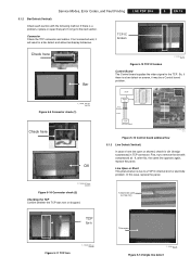
... one. Service Modes, Error Codes, and Fault Finding 5.1.1 No Display Check each section with the naked eye. If it is a problem, replace or repair that part. Connectors Check all connectors (PSU, Y-SUS, CTRL, Z-SUS). EN 13 G_16390_039.eps 110806 Figure 5-3 Control + Y-SUS board G_16390_042.eps 010906 Figure 5-6 Signal input (LVDS) Exhaust...
... one. Service Modes, Error Codes, and Fault Finding 5.1.1 No Display Check each section with the naked eye. If it is a problem, replace or repair that part. Connectors Check all connectors (PSU, Y-SUS, CTRL, Z-SUS). EN 13 G_16390_039.eps 110806 Figure 5-3 Control + Y-SUS board G_16390_042.eps 010906 Figure 5-6 Signal input (LVDS) Exhaust...

Service Manual
Page 14
... figure "PSU trouble shooting") 1. Voltage Check (5V, Va, Vs). The power protection function protects the boards when a short occurs on ). EN 14 5. Check each unit part of a PSU protection, disconnect the power supply connectors to the boards, to Module Label) Check fuse - from AC to adjust Va Voltage ADJ (VR351) (Va...
... figure "PSU trouble shooting") 1. Voltage Check (5V, Va, Vs). The power protection function protects the boards when a short occurs on ). EN 14 5. Check each unit part of a PSU protection, disconnect the power supply connectors to the boards, to Module Label) Check fuse - from AC to adjust Va Voltage ADJ (VR351) (Va...
Service Manual
Page 15
... Control Board The Control board supplies the video signal to the next section. Line Open or Short This phenomenon is a problem, replace or repair that part. MCM Buffer IC Array Resistor 6 line R - First, try to a TCP IC internal short or electrode problem. Service Modes, Error Codes, and Fault Finding LGE PDP...
... Control Board The Control board supplies the video signal to the next section. Line Open or Short This phenomenon is a problem, replace or repair that part. MCM Buffer IC Array Resistor 6 line R - First, try to a TCP IC internal short or electrode problem. Service Modes, Error Codes, and Fault Finding LGE PDP...

Service Manual
Page 16
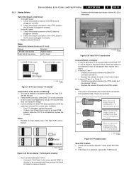
...not plugged in well, it can result in a horizontal bar, because the sustain voltage cannot be replaced separately. In case of adherence between a part of the film and the rear panel electrode, or a panel electrode open Panel electrode Insulation break down Horizontal bar F_15590_085.eps 060705 Figure 5-16 ... defect. Disconnected Screen off F_15590_086.eps 060705 Figure 5-17 Check drive connectors Scan IC Check Check the diode value of the right side part of CTRL board defect. So replace the CTRL board. LGE PDP 2K6 Service Modes, Error Codes, and Fault Finding Line Open or ...
...not plugged in well, it can result in a horizontal bar, because the sustain voltage cannot be replaced separately. In case of adherence between a part of the film and the rear panel electrode, or a panel electrode open Panel electrode Insulation break down Horizontal bar F_15590_085.eps 060705 Figure 5-16 ... defect. Disconnected Screen off F_15590_086.eps 060705 Figure 5-17 Check drive connectors Scan IC Check Check the diode value of the right side part of CTRL board defect. So replace the CTRL board. LGE PDP 2K6 Service Modes, Error Codes, and Fault Finding Line Open or ...

Service Manual
Page 17
Service Modes, Error Codes, and Fault Finding Scan IC Check Check diode value of the right side part of X, Y, and Z boards with an oscilloscope (> 200 MHz) and find the troubled board by comparing the output wave with the figures below ). 5. Check these boards ...
Service Modes, Error Codes, and Fault Finding Scan IC Check Check diode value of the right side part of X, Y, and Z boards with an oscilloscope (> 200 MHz) and find the troubled board by comparing the output wave with the figures below ). 5. Check these boards ...
Service Manual
Page 19
...ohmmeter, and then examine the diode in correctly. • Replace relevant X board. Check if the 60-pin connection of the CTRL board to the part of the Data TCP IC unit as shown in correctly. • On the XL board: 1. Check the connection between the X board and the heatsink... the Data TCP connector and the IC. - Case 1 Case 2 Case 3 All Partial Not at all F_15590_009.eps 040705 Figure 5-25 Screen display "Vertical parts missing" • How to the XL board is not defective, replace the X board. G_16390_081.eps 010906 Figure 5-26 Data TCP IC examination Unusual Pattern on...
...ohmmeter, and then examine the diode in correctly. • Replace relevant X board. Check if the 60-pin connection of the CTRL board to the part of the Data TCP IC unit as shown in correctly. • On the XL board: 1. Check the connection between the X board and the heatsink... the Data TCP connector and the IC. - Case 1 Case 2 Case 3 All Partial Not at all F_15590_009.eps 040705 Figure 5-25 Screen display "Vertical parts missing" • How to the XL board is not defective, replace the X board. G_16390_081.eps 010906 Figure 5-26 Data TCP IC examination Unusual Pattern on...

Service Manual
Page 20
... several horizontal lines including left case F_15590_018.eps 060605 Figure 5-29 Scan IC Vertical Lines with regular gap" Data Copy in a quarter or other division part of screen including left case F_15590_022.eps 040705 Figure 5-33 Screen display "Horizontal lines" Low Brightness of the SCAN IC - Open or short circuit on...
... several horizontal lines including left case F_15590_018.eps 060605 Figure 5-29 Scan IC Vertical Lines with regular gap" Data Copy in a quarter or other division part of screen including left case F_15590_022.eps 040705 Figure 5-33 Screen display "Horizontal lines" Low Brightness of the SCAN IC - Open or short circuit on...

Service Manual
Page 22
... damaged, the STB signal is not shown. - Wave format: As shown in figure below . - In most cases you can see a burn mark on the corresponding part, or mis-discharge. Wave format: No output wave. When STB signal is not generated. 2. Wave format: Output wave is generated again, the output must maintain...
... damaged, the STB signal is not shown. - Wave format: As shown in figure below . - In most cases you can see a burn mark on the corresponding part, or mis-discharge. Wave format: No output wave. When STB signal is not generated. 2. Wave format: Output wave is generated again, the output must maintain...


