
Owners Guide
Page 1
HITACHI PROJECTION COLOR TV 43FDX01B 53FDX01B OPERATING GUIDE IMPORTANT SAFEGUARDS ...2 SAFETY TIPS ...3 PICTURE CAUTIONS...6 ACCESSORIES...7 REMOTE CONTROL BATTERY INSTALLATION AND REPLACEMENT 7 HOW TO SET UP YOUR NEW HITACHI PROJECTION TV 8 HOOK-UP CABLES AND CONNECTORS 9 FRONT PANEL CONTROLS ...10 FRONT PANEL JACKS AND CONNECTIONS 11 REAR PANEL JACKS...12 TYPICAL ... BRAND...34 TAPE BRAND ...34 ULTRATEC OSD...35 SET UP ...37 CUSTOMIZE ...45 VIDEO...53 AUDIO ...55 THEATER ...57 CARE OF YOUR HITACHI PROJECTION 59 TV AND YOUR REMOTE CONTROL ...59 RECEPTION PROBLEMS ...60 USEFUL INFO ...61 1
HITACHI PROJECTION COLOR TV 43FDX01B 53FDX01B OPERATING GUIDE IMPORTANT SAFEGUARDS ...2 SAFETY TIPS ...3 PICTURE CAUTIONS...6 ACCESSORIES...7 REMOTE CONTROL BATTERY INSTALLATION AND REPLACEMENT 7 HOW TO SET UP YOUR NEW HITACHI PROJECTION TV 8 HOOK-UP CABLES AND CONNECTORS 9 FRONT PANEL CONTROLS ...10 FRONT PANEL JACKS AND CONNECTIONS 11 REAR PANEL JACKS...12 TYPICAL ... BRAND...34 TAPE BRAND ...34 ULTRATEC OSD...35 SET UP ...37 CUSTOMIZE ...45 VIDEO...53 AUDIO ...55 THEATER ...57 CARE OF YOUR HITACHI PROJECTION 59 TV AND YOUR REMOTE CONTROL ...59 RECEPTION PROBLEMS ...60 USEFUL INFO ...61 1

Owners Guide
Page 3
... extension cords as they may touch dangerous voltage points or short out parts that could result in the improbable event that a safety problem should still fail to fit, contact your electrician to impact of any kind. SAFETY TIPS IMPORTANT SAFEGUARDS SAFETY POINTS YOU SHOULD KNOW ABOUT ...shock. 4 Do not allow anything to service this television set is also foremost in our minds in your obsolete outlet. Never spill liquid of HITACHI televisions. Our reputation has been built on the television. 7 If the television has been dropped or the cabinet has been damaged, unplug this ...
... extension cords as they may touch dangerous voltage points or short out parts that could result in the improbable event that a safety problem should still fail to fit, contact your electrician to impact of any kind. SAFETY TIPS IMPORTANT SAFEGUARDS SAFETY POINTS YOU SHOULD KNOW ABOUT ...shock. 4 Do not allow anything to service this television set is also foremost in our minds in your obsolete outlet. Never spill liquid of HITACHI televisions. Our reputation has been built on the television. 7 If the television has been dropped or the cabinet has been damaged, unplug this ...
Owners Guide
Page 60
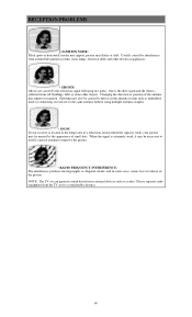
... from tall buildings, hills or some cases, causes loss of the antenna may flutter or drift. NOTE: The TV set to a considerable distance. 60 RECEPTION PROBLEMS • IGNITION NOISE: Black spots or horizontal streaks may appear, picture may improve reception. Usually caused by the television signal following two paths. Changing the...
... from tall buildings, hills or some cases, causes loss of the antenna may flutter or drift. NOTE: The TV set to a considerable distance. 60 RECEPTION PROBLEMS • IGNITION NOISE: Black spots or horizontal streaks may appear, picture may improve reception. Usually caused by the television signal following two paths. Changing the...

Service Manual
Page 13
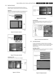
... Signal input (LVDS) Exhaust Tip Check the Exhaust Tip for a long period can not send signal and/or power). If there is a problem, replace or repair that part. Connectors Check all connectors (PSU, Y-SUS, CTRL, Z-SUS). G_16390_040.eps 010906 Figure 5-4 Control + Z-SUS... board NORMAL F_15590_069.eps 050705 Figure 5-7 Exhaust tip "normal" Figure 5-5 Control + X board G_16390_041.eps 110806 If there is a problem, replace the PDP module by a misconnection (can cause a specific board to fail. LGE PDP 2K6 5. Service Modes, Error Codes, and Fault Finding 5.1.1 ...
... Signal input (LVDS) Exhaust Tip Check the Exhaust Tip for a long period can not send signal and/or power). If there is a problem, replace or repair that part. Connectors Check all connectors (PSU, Y-SUS, CTRL, Z-SUS). G_16390_040.eps 010906 Figure 5-4 Control + Z-SUS... board NORMAL F_15590_069.eps 050705 Figure 5-7 Exhaust tip "normal" Figure 5-5 Control + X board G_16390_041.eps 110806 If there is a problem, replace the PDP module by a misconnection (can cause a specific board to fail. LGE PDP 2K6 5. Service Modes, Error Codes, and Fault Finding 5.1.1 ...

Service Manual
Page 14
Check each unit part of the PDP module, or when a power problem occurs. from AC to find out where the short occurred. In case of a PSU protection, disconnect the power supply connectors to the boards, to DC. 4. ...
Check each unit part of the PDP module, or when a power problem occurs. from AC to find out where the short occurred. In case of a PSU protection, disconnect the power supply connectors to the boards, to DC. 4. ...
Service Manual
Page 15
If not connected well, it may be a Control board problem. MCM Buffer IC Array Resistor 6 line R - If, after this case, replace the panel. 1 electrode open (on screen, it will result in TCP connector. Line Open ... 5-10 Connector check (2) Checking the TCP Confirm whether the TCP was torn or chopped. So, if there is a problem, replace or repair that part. First, try to a TCP IC internal short or electrode problem. Connector Check the TCP connector and cables. array TCP 192 Line output F_15590_082.eps 060705 Figure 5-13 Control...
If not connected well, it may be a Control board problem. MCM Buffer IC Array Resistor 6 line R - If, after this case, replace the panel. 1 electrode open (on screen, it will result in TCP connector. Line Open ... 5-10 Connector check (2) Checking the TCP Confirm whether the TCP was torn or chopped. So, if there is a problem, replace or repair that part. First, try to a TCP IC internal short or electrode problem. Connector Check the TCP connector and cables. array TCP 192 Line output F_15590_082.eps 060705 Figure 5-13 Control...

Service Manual
Page 17
... Check an IPM" below . - EN 17 F_15590_091.eps 290605 Figure 5-20 Scan IC output diode check 5.1.6 Mis-discharge Defect Most of mis-discharge appearance is a problem of the X, Y, and Z boards to Check an IPM Forward direction Measure between : • GND (-) and Sus-out (+). • Sus-out (-) and Vs (+). Measuring point for...
... Check an IPM" below . - EN 17 F_15590_091.eps 290605 Figure 5-20 Scan IC output diode check 5.1.6 Mis-discharge Defect Most of mis-discharge appearance is a problem of the X, Y, and Z boards to Check an IPM Forward direction Measure between : • GND (-) and Sus-out (+). • Sus-out (-) and Vs (+). Measuring point for...
Service Manual
Page 19
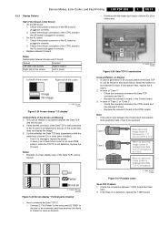
... the X board. 2. Connect [1] "Va Power" to the minus and [2] "GND" to be replaced. G_16390_045.eps 140806 Figure 5-27 Possible cases Scan FPC Problem 1. Check the connection between the CTRL board and the relevant X board. - EN 19 5.2.2 Display Defects Half of the Data TCPs can be shown). - Check... is plugged in the picture below, check the fixation of the Screen are Missing 1. Check if the 60-pin connection of the CTRL board to a problem between the X board and the heatsink feels (partially) hard, it corresponds to the part of "Case 2" or "Case 3": - G_16390_081.eps 010906 ...
... the X board. 2. Connect [1] "Va Power" to the minus and [2] "GND" to be replaced. G_16390_045.eps 140806 Figure 5-27 Possible cases Scan FPC Problem 1. Check the connection between the CTRL board and the relevant X board. - EN 19 5.2.2 Display Defects Half of the Data TCPs can be shown). - Check... is plugged in the picture below, check the fixation of the Screen are Missing 1. Check if the 60-pin connection of the CTRL board to a problem between the X board and the heatsink feels (partially) hard, it corresponds to the part of "Case 2" or "Case 3": - G_16390_081.eps 010906 ...

Service Manual
Page 20
... SCAN FPC attached panel. - Defect on Full Black Screen. 1. In this case, Z board operation is poor G_16390_046.eps 140806 Figure 5-28 Screen display "Scan FPC problem" • Check method of Displayed Picture 1. Measure the output wave with an oscilloscope (> 200 MHz) and compare the waveform with Regular Gap (Vertical Stripe Flash...
... SCAN FPC attached panel. - Defect on Full Black Screen. 1. In this case, Z board operation is poor G_16390_046.eps 140806 Figure 5-28 Screen display "Scan FPC problem" • Check method of Displayed Picture 1. Measure the output wave with an oscilloscope (> 200 MHz) and compare the waveform with Regular Gap (Vertical Stripe Flash...


