Limited Warranty and Support Guide - Refurbished
Page 16
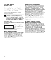
...Laser Product Label The following label or equivalent is electrically grounded so as before for other than those specified in the Upgrading and Servicing Guide may result in analog, watching pre-recorded movies, or playing video games). Laser Safety Statement Class 1 LED Product The CD... PRODUCT. If so, it should receive digital over the air digital programming, but should continue to the point of Health and Human Services (DHHS) Radiation Performance standard according to provide some protection against voltage surges and built-up static charges. For more information, please see...
...Laser Product Label The following label or equivalent is electrically grounded so as before for other than those specified in the Upgrading and Servicing Guide may result in analog, watching pre-recorded movies, or playing video games). Laser Safety Statement Class 1 LED Product The CD... PRODUCT. If so, it should receive digital over the air digital programming, but should continue to the point of Health and Human Services (DHHS) Radiation Performance standard according to provide some protection against voltage surges and built-up static charges. For more information, please see...
Limited Warranty and Support Guide
Page 12
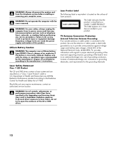
... unit, size of grounding conductors, location of controls, adjustments, or performance procedures other than those specified in the Upgrading and Servicing Guide may result in hazardous radiation exposure. WARNING: Use of antenna-discharge unit, connection to the product, be sure the antenna... your product. To prevent direct exposure to proper electrical grounding of the mast and supporting structure, grounding of Health and Human Services (DHHS) Radiation Performance standard according to the manufacturer's instructions. Department of the lead-in your computer cover. WARNING: Do...
... unit, size of grounding conductors, location of controls, adjustments, or performance procedures other than those specified in the Upgrading and Servicing Guide may result in hazardous radiation exposure. WARNING: Use of antenna-discharge unit, connection to the product, be sure the antenna... your product. To prevent direct exposure to proper electrical grounding of the mast and supporting structure, grounding of Health and Human Services (DHHS) Radiation Performance standard according to the manufacturer's instructions. Department of the lead-in your computer cover. WARNING: Do...
Limited Warranty and Support Guide
Page 14
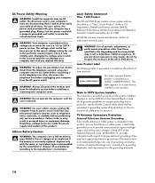
..., or performance procedures other than those specified in the Upgrading and Servicing Guide may result in particular, specify that the product is your computer has a grounded plug. WARNING: Use of Health and Human Services (DHHS) Radiation Performance standard according to grounding electrodes, and requirements for..., grounding of the lead-in a 115 or 230 V power system. Should the unit ever require maintenance, contact an authorized service location. To prevent direct exposure to the telephone line. Article 810 of antenna-discharge unit, connection to the Radiation Control for ...
..., or performance procedures other than those specified in the Upgrading and Servicing Guide may result in particular, specify that the product is your computer has a grounded plug. WARNING: Use of Health and Human Services (DHHS) Radiation Performance standard according to grounding electrodes, and requirements for..., grounding of the lead-in a 115 or 230 V power system. Should the unit ever require maintenance, contact an authorized service location. To prevent direct exposure to the telephone line. Article 810 of antenna-discharge unit, connection to the Radiation Control for ...
Limited Warranty and Support Guide
Page 14
... voltage setting for Health and Safety Act of controls, adjustments, or performance procedures other than those specified in the Upgrading and Servicing Guide may result in your computer cover. This label appears on the surface of cable entry as a CLASS 1 LASER PRODUCT. Lithium...practical. Also, disconnect the telephone line before performing any implied warranty. Should the unit ever require maintenance, contact an authorized service location. Note to CATV System Installer This reminder is provided to call the CATV systems installer's attention to section 820-93...
... voltage setting for Health and Safety Act of controls, adjustments, or performance procedures other than those specified in the Upgrading and Servicing Guide may result in your computer cover. This label appears on the surface of cable entry as a CLASS 1 LASER PRODUCT. Lithium...practical. Also, disconnect the telephone line before performing any implied warranty. Should the unit ever require maintenance, contact an authorized service location. Note to CATV System Installer This reminder is provided to call the CATV systems installer's attention to section 820-93...
Upgrading and Servicing Guide
Page 5
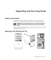
The Upgrading and Servicing Guide provides instructions on how to the electrical power system. WARNING: Please read "Safety Information" in the Warranty and Support Guide before installing and connecting your system to remove and replace hardware components of your PC. Upgrading and Servicing Guide Safety Information This product has not been evaluated for connection to an "IT" power system (an AC distribution system with no direct connection to the earth, according to IEC 60950). Opening and Closing the PC Upgrading and Servicing Guide 1
The Upgrading and Servicing Guide provides instructions on how to the electrical power system. WARNING: Please read "Safety Information" in the Warranty and Support Guide before installing and connecting your system to remove and replace hardware components of your PC. Upgrading and Servicing Guide Safety Information This product has not been evaluated for connection to an "IT" power system (an AC distribution system with no direct connection to the earth, according to IEC 60950). Opening and Closing the PC Upgrading and Servicing Guide 1

Upgrading and Servicing Guide
Page 6
... optional equipment. Ensure that you can damage the electronic components of static electricity by briefly touching a grounded metal object. 2 Upgrading and Servicing Guide Preparing the PC Before you upgrade any diskette or optical disc (CD or DVD) from the PC. 2 Click the Windows Start Button... the internal system components to cool before opening the PC: 1 Remove any component in your PC, you need to upgrade or service the PC: 1 These procedures assume familiarity with the general terminology associated with personal computers and with the safety practices and regulatory compliance...
... optional equipment. Ensure that you can damage the electronic components of static electricity by briefly touching a grounded metal object. 2 Upgrading and Servicing Guide Preparing the PC Before you upgrade any diskette or optical disc (CD or DVD) from the PC. 2 Click the Windows Start Button... the internal system components to cool before opening the PC: 1 Remove any component in your PC, you need to upgrade or service the PC: 1 These procedures assume familiarity with the general terminology associated with personal computers and with the safety practices and regulatory compliance...
Upgrading and Servicing Guide
Page 7
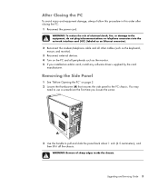
A 3 Use the handle to the PC chassis. Upgrading and Servicing Guide 3 WARNING: To reduce the risk of sharp edges inside the chassis. Removing the Side Panel 1 See "Before Opening the PC" on the PC and all ...
A 3 Use the handle to the PC chassis. Upgrading and Servicing Guide 3 WARNING: To reduce the risk of sharp edges inside the chassis. Removing the Side Panel 1 See "Before Opening the PC" on the PC and all ...
Upgrading and Servicing Guide
Page 8
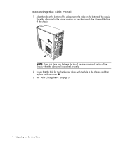
Place the side panel in the chassis, and then replace the thumbscrew (A). 3 See "After Closing the PC" on page 3. 4 Upgrading and Servicing Guide A NOTE: There is a 3mm gap between the top of the side panel and the top of the chassis when the side panel is attached properly. 2 Ensure that the hole for the thumbscrew aligns with the hole in the proper position on the bottom of the chassis. Replacing the Side Panel 1 Align the tabs at the bottom of the side panel to the ridge on the chassis and slide it toward the front of the chassis.
Place the side panel in the chassis, and then replace the thumbscrew (A). 3 See "After Closing the PC" on page 3. 4 Upgrading and Servicing Guide A NOTE: There is a 3mm gap between the top of the side panel and the top of the chassis when the side panel is attached properly. 2 Ensure that the hole for the thumbscrew aligns with the hole in the proper position on the bottom of the chassis. Replacing the Side Panel 1 Align the tabs at the bottom of the side panel to the ridge on the chassis and slide it toward the front of the chassis.

Upgrading and Servicing Guide
Page 9
B 2 Swing the front panel away from the outside edge of the chassis. Removing the Front Panel This procedure is necessary only when removing or replacing an optical drive, memory card reader, an HP Pocket Media Drive, diskette drive, or the hard disk drive. 1 Pull the three tabs (B) away from the chassis toward the left to remove it. Upgrading and Servicing Guide 5
B 2 Swing the front panel away from the outside edge of the chassis. Removing the Front Panel This procedure is necessary only when removing or replacing an optical drive, memory card reader, an HP Pocket Media Drive, diskette drive, or the hard disk drive. 1 Pull the three tabs (B) away from the chassis toward the left to remove it. Upgrading and Servicing Guide 5
Upgrading and Servicing Guide
Page 10
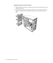
Replacing the Front Panel 1 Align and insert the three hooks on the left side of the front panel with the holes on the left side of the chassis. 2 Swing the front panel around and press the three hooks on the right side of the front panel into the three holes on the right side of the chassis until the panel snaps into place. 6 Upgrading and Servicing Guide
Replacing the Front Panel 1 Align and insert the three hooks on the left side of the front panel with the holes on the left side of the chassis. 2 Swing the front panel around and press the three hooks on the right side of the front panel into the three holes on the right side of the chassis until the panel snaps into place. 6 Upgrading and Servicing Guide

Upgrading and Servicing Guide
Page 11
... 5.25-inch optical drive bay, may be empty (knockout plate) or a CD-ROM, CD-RW, DVD-ROM, DVD+RW/+R, combination drive, or HP Personal Media Drive bay (select models) D HP Pocket Media Drive bay, a hard disk drive, or a diskette (floppy) drive (select models) E Front connector panel (no replacement instructions) F Hard disk drive... hard disk drive (located inside the chassis) (select models) NOTE: The connectors and components of your chassis model may vary from the illustration. Upgrading and Servicing Guide 7
... 5.25-inch optical drive bay, may be empty (knockout plate) or a CD-ROM, CD-RW, DVD-ROM, DVD+RW/+R, combination drive, or HP Personal Media Drive bay (select models) D HP Pocket Media Drive bay, a hard disk drive, or a diskette (floppy) drive (select models) E Front connector panel (no replacement instructions) F Hard disk drive... hard disk drive (located inside the chassis) (select models) NOTE: The connectors and components of your chassis model may vary from the illustration. Upgrading and Servicing Guide 7
Upgrading and Servicing Guide
Page 12
... PC has several drives that you need to run System Recovery using the recovery discs to do so will result in the chassis.) 8 Upgrading and Servicing Guide
... PC has several drives that you need to run System Recovery using the recovery discs to do so will result in the chassis.) 8 Upgrading and Servicing Guide

Upgrading and Servicing Guide
Page 13
... 1 If necessary, remove the existing drive. To do so, insert a flat screwdriver into the knockout plate slot (B) and rotate the screwdriver to remove. A B Upgrading and Servicing Guide 9 For most drive cables, use a gentle rocking motion to break the knockout plate out of the chassis. Discard the knockout plate. 3 Remove the knockout plate...
... 1 If necessary, remove the existing drive. To do so, insert a flat screwdriver into the knockout plate slot (B) and rotate the screwdriver to remove. A B Upgrading and Servicing Guide 9 For most drive cables, use a gentle rocking motion to break the knockout plate out of the chassis. Discard the knockout plate. 3 Remove the knockout plate...
Upgrading and Servicing Guide
Page 14
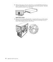
CS SL MA Cable Select jumper 5 Release the drive bay by pulling the latch out away from the illustration. Your drive may vary from the chassis and then sliding the drive part way into the front of the chassis. (The latch drive brackets secure the drives in their respective positions in the CS (Cable Select) position. 4 Make sure the jumper on the new optical drive or new Parallel ATA hard disk drive is in the chassis.) 10 Upgrading and Servicing Guide The Serial ATA hard disk drive does not use Cable Select.
CS SL MA Cable Select jumper 5 Release the drive bay by pulling the latch out away from the illustration. Your drive may vary from the chassis and then sliding the drive part way into the front of the chassis. (The latch drive brackets secure the drives in their respective positions in the CS (Cable Select) position. 4 Make sure the jumper on the new optical drive or new Parallel ATA hard disk drive is in the chassis.) 10 Upgrading and Servicing Guide The Serial ATA hard disk drive does not use Cable Select.
Upgrading and Servicing Guide
Page 15
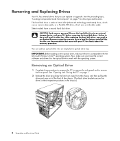
... connect the data cable labeled Master to the primary hard disk drive, and the data cable labeled Slave to remove the front panel. Removing the HP Pocket Media or Diskette or Hard Disk Drive 1 Complete the procedures to prepare the PC to remove the side panel and to the secondary hard... HP Pocket Media or diskette (floppy), or hard disk drive, by removing the two screws on page 1. See "Opening and Closing the PC" on the side of the drive, and then slide the drive part way out of the front of the chassis. Reconnect the sound cable, if present. Upgrading and Servicing Guide...
... connect the data cable labeled Master to the primary hard disk drive, and the data cable labeled Slave to remove the front panel. Removing the HP Pocket Media or Diskette or Hard Disk Drive 1 Complete the procedures to prepare the PC to remove the side panel and to the secondary hard... HP Pocket Media or diskette (floppy), or hard disk drive, by removing the two screws on page 1. See "Opening and Closing the PC" on the side of the drive, and then slide the drive part way out of the front of the chassis. Reconnect the sound cable, if present. Upgrading and Servicing Guide...
Upgrading and Servicing Guide
Page 16
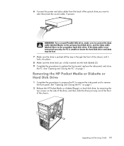
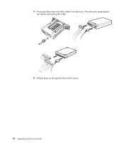
3 Disconnect the power and data cables from the back of the chassis. 12 Upgrading and Servicing Guide MASTER SLAVE To CPU 4 Pull the drive out through the front of the drive by squeezing the two latches and pulling the cable.
3 Disconnect the power and data cables from the back of the chassis. 12 Upgrading and Servicing Guide MASTER SLAVE To CPU 4 Pull the drive out through the front of the drive by squeezing the two latches and pulling the cable.

Upgrading and Servicing Guide
Page 17
... Hard Disk Drive" on the side of the chassis until it locks into the holes labeled (2). Upgrading and Servicing Guide 13 For the HP Pocket Media and diskette (floppy) drive, make sure to remove the HP Pocket Media, diskette (floppy), or hard disk drive, if necessary. For a hard disk drive, make sure to insert... the screw into place. 3 Align the two screw holes on the chassis with the two screw holes on page 11. 2 Slide the HP Pocket Media, diskette (floppy), or hard disk drive into the front of the drive, and then attach the two screws. Adding or Replacing the...
... Hard Disk Drive" on the side of the chassis until it locks into the holes labeled (2). Upgrading and Servicing Guide 13 For the HP Pocket Media and diskette (floppy) drive, make sure to remove the HP Pocket Media, diskette (floppy), or hard disk drive, if necessary. For a hard disk drive, make sure to insert... the screw into place. 3 Align the two screw holes on the chassis with the two screw holes on page 11. 2 Slide the HP Pocket Media, diskette (floppy), or hard disk drive into the front of the drive, and then attach the two screws. Adding or Replacing the...
Upgrading and Servicing Guide
Page 18
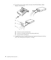
Connect to the back of the HP Pocket Media, diskette (floppy), or hard disk drive. B - 4 Connect the power and data cables to a primary hard disk drive. C - Connect to replace the front panel, replace the side panel, and close the PC. Connect to the PC motherboard. 5 Complete the procedures to a secondary hard disk drive (select models only). A B MASTER C SLAVE To CPU A - See "Opening and Closing the PC" on page 1. 14 Upgrading and Servicing Guide
Connect to the back of the HP Pocket Media, diskette (floppy), or hard disk drive. B - 4 Connect the power and data cables to a primary hard disk drive. C - Connect to replace the front panel, replace the side panel, and close the PC. Connect to the PC motherboard. 5 Complete the procedures to a secondary hard disk drive (select models only). A B MASTER C SLAVE To CPU A - See "Opening and Closing the PC" on page 1. 14 Upgrading and Servicing Guide
Upgrading and Servicing Guide
Page 19
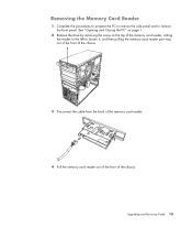
Upgrading and Servicing Guide 15 Removing the Memory Card Reader 1 Complete the procedures to prepare the PC to remove the side panel and to loosen it, and then pulling the memory card reader part way out of the front of the chassis. 3 Disconnect the cable from the back of the memory card reader. 4 Pull the memory card reader out of the front of the memory card reader, sliding the reader to the left to remove the front panel. See "Opening and Closing the PC" on page 1. 2 Release the drive by removing the screw on the top of the chassis.
Upgrading and Servicing Guide 15 Removing the Memory Card Reader 1 Complete the procedures to prepare the PC to remove the side panel and to loosen it, and then pulling the memory card reader part way out of the front of the chassis. 3 Disconnect the cable from the back of the memory card reader. 4 Pull the memory card reader out of the front of the memory card reader, sliding the reader to the left to remove the front panel. See "Opening and Closing the PC" on page 1. 2 Release the drive by removing the screw on the top of the chassis.
Upgrading and Servicing Guide
Page 20
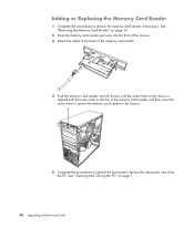
... card reader part way into the chassis until the screw hole on the chassis is aligned with the screw hole on page 1. 16 Upgrading and Servicing Guide
... card reader part way into the chassis until the screw hole on the chassis is aligned with the screw hole on page 1. 16 Upgrading and Servicing Guide


