

User Manual
Page 3
ProCurve Switch 1800-24G Installation and Getting Started Guide
ProCurve Switch 1800-24G Installation and Getting Started Guide
User Manual
Page 4
...prior written consent of Hewlett-Packard. A copy of this material. Publication Number 5991-4724 October 2006 Applicable Product ProCurve Switch 1800-24G (J9028A) Safety Before installing and operating this document may be obtained from your Hewlett-Packard products and replacement parts can be photocopied... This document contains proprietary information, which is not furnished by copyright. Hewlett-Packard assumes no responsibility for HP products and services are set forth in Appendix B, "Safety and EMC Regulatory Statements". © Copyright 2006 Hewlett-Packard Development Company,...
...prior written consent of Hewlett-Packard. A copy of this material. Publication Number 5991-4724 October 2006 Applicable Product ProCurve Switch 1800-24G (J9028A) Safety Before installing and operating this document may be obtained from your Hewlett-Packard products and replacement parts can be photocopied... This document contains proprietary information, which is not furnished by copyright. Hewlett-Packard assumes no responsibility for HP products and services are set forth in Appendix B, "Safety and EMC Regulatory Statements". © Copyright 2006 Hewlett-Packard Development Company,...
User Manual
Page 5
... the Network Cables 2-10 6. Contents 1 Switch Overview Switch Hardware Features 1-1 LEDs 1-2 LED Mode Select Button and Indicator LEDs 1-2 Switch Features 1-3 2 Installing the Switch Included Parts 2-1 Installation Procedure 2-2 Installation Precautions 2-2 1. Prepare the Installation Site 2-3 2. Verify the Switch Passes Self Test 2-4 3. Installing or Removing mini-GBICs 2-10 3 Configuring the Switch Initial Configuration 3-1 Changing the PC's IP Address 3-2 Where...
... the Network Cables 2-10 6. Contents 1 Switch Overview Switch Hardware Features 1-1 LEDs 1-2 LED Mode Select Button and Indicator LEDs 1-2 Switch Features 1-3 2 Installing the Switch Included Parts 2-1 Installation Procedure 2-2 Installation Precautions 2-2 1. Prepare the Installation Site 2-3 2. Verify the Switch Passes Self Test 2-4 3. Installing or Removing mini-GBICs 2-10 3 Configuring the Switch Initial Configuration 3-1 Changing the PC's IP Address 3-2 Where...
User Manual
Page 6
ProCurve Networking Customer Support Services 4-4 Before Calling Support 4-4 A Switch Specifications Physical A-1 Electrical A-1 Environmental A-1 Acoustic A-2 Connectors A-2 Safety A-2 Lasers A-2 B Safety and EMC Regulatory Statements Safety Information B-1 EMC Regulatory Statements B-8 C Recycle Statements Waste Electrical and Electronic Equipment (WEEE) Statements C-1 Index vi
ProCurve Networking Customer Support Services 4-4 Before Calling Support 4-4 A Switch Specifications Physical A-1 Electrical A-1 Environmental A-1 Acoustic A-2 Connectors A-2 Safety A-2 Lasers A-2 B Safety and EMC Regulatory Statements Safety Information B-1 EMC Regulatory Statements B-8 C Recycle Statements Waste Electrical and Electronic Equipment (WEEE) Statements C-1 Index vi
User Manual
Page 7
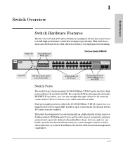
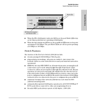
... indicator LEDs 10/100/1000Base-T RJ-45 ports Dual-personality ports (10/100/1000Base-T or mini-GBIC) Switch Ports The switch has 24 auto-sensing 10/100/1000Base-T RJ-45 ports and two dualpersonality ports (ports 23 and 24)....switched network infrastructure by connecting the switch to be used primarily as a high-density wiring closet or desktop switch. By default, the RJ45 connectors are enabled. In addition, the switch offers network management capabilities. 1-1 Switch Overview 1 Switch Overview Switch Hardware Features The ProCurve Switch 1800-24G (J9028A) is a multiport switch...
... indicator LEDs 10/100/1000Base-T RJ-45 ports Dual-personality ports (10/100/1000Base-T or mini-GBIC) Switch Ports The switch has 24 auto-sensing 10/100/1000Base-T RJ-45 ports and two dualpersonality ports (ports 23 and 24)....switched network infrastructure by connecting the switch to be used primarily as a high-density wiring closet or desktop switch. By default, the RJ45 connectors are enabled. In addition, the switch offers network management capabilities. 1-1 Switch Overview 1 Switch Overview Switch Hardware Features The ProCurve Switch 1800-24G (J9028A) is a multiport switch...
User Manual
Page 8
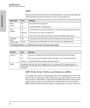
...indicator LEDs near the button. Flashing Indicates that are lit for full-duplex operation or indicates the operating speed. A fault has occurred with the switch fan. LED Mode Select (2 green LEDs) FDx Speed Indicates the port Mode LEDs are in 1000 Mbps mode. * The blinking behavior is ...for each of information that are lit for ports that can be displayed for system monitoring. The following table details the functions of the switch provides status LEDs for each port. Indicates the port Mode LEDs are in full-duplex mode. LED Mode Select Button and Indicator LEDs ...
...indicator LEDs near the button. Flashing Indicates that are lit for full-duplex operation or indicates the operating speed. A fault has occurred with the switch fan. LED Mode Select (2 green LEDs) FDx Speed Indicates the port Mode LEDs are in 1000 Mbps mode. * The blinking behavior is ...for each of information that are lit for ports that can be displayed for system monitoring. The following table details the functions of the switch provides status LEDs for each port. Indicates the port Mode LEDs are in full-duplex mode. LED Mode Select Button and Indicator LEDs ...
User Manual
Page 9
... at 10 Mbps or 100 Mbps. Cross-over cables are off for all connections can be made using straight-through twisted-pair cables. if the switch detects that a 10/100 Mbps end-node device is connected to the port, it configures the port as MDI-X. ■ automatic learning of the ProCurve... Switch 1800-24G include: ■ 24 auto-sensing 10/100/1000Base-T RJ-45 ports. ■ plug-and-play networking-all ports are enabled-just connect the ...
... at 10 Mbps or 100 Mbps. Cross-over cables are off for all connections can be made using straight-through twisted-pair cables. if the switch detects that a 10/100 Mbps end-node device is connected to the port, it configures the port as MDI-X. ■ automatic learning of the ProCurve... Switch 1800-24G include: ■ 24 auto-sensing 10/100/1000Base-T RJ-45 ports. ■ plug-and-play networking-all ports are enabled-just connect the ...
User Manual
Page 10
... support for up to 64 IEEE 802.1Q-compliant VLANs so you can be accessed from within their network and launch the ProCurve Switch 1800's built-in graphical interface that can divide the attached end nodes into logical groupings that fit your business needs. ■... support for up to 12 trunks so you to assign physical links to enhance network performance- Switch Overview Switch Overview Switch Hardware Features ■ easy management of new switch software for many advanced features to one logical link (trunk) that functions as a single, higher-speed link providing...
... support for up to 64 IEEE 802.1Q-compliant VLANs so you can be accessed from within their network and launch the ProCurve Switch 1800's built-in graphical interface that can divide the attached end nodes into logical groupings that fit your business needs. ■... support for up to 12 trunks so you to assign physical links to enhance network performance- Switch Overview Switch Overview Switch Hardware Features ■ easy management of new switch software for many advanced features to one logical link (trunk) that functions as a single, higher-speed link providing...
User Manual
Page 11
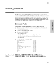
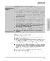
... the following components ship with rubber feet that includes the brackets for mounting the switch in a standard 19-inch telco rack, in an equipment cabinet, and with a ProCurve Switch 1800-24G: ■ ProCurve Switch 1800-24G Installation and Getting Started Guide (5991-4724), this manual ■ Customer...-2085) • two mounting brackets • eight 8-mm M4 screws to attach the mounting brackets to the switch • four 5/8-inch number 12-24 screws to attach the switch to a rack • four rubber feet ■ Power cord, one of locations and orientations. This chapter ...
... the following components ship with rubber feet that includes the brackets for mounting the switch in a standard 19-inch telco rack, in an equipment cabinet, and with a ProCurve Switch 1800-24G: ■ ProCurve Switch 1800-24G Installation and Getting Started Guide (5991-4724), this manual ■ Customer...-2085) • two mounting brackets • eight 8-mm M4 screws to attach the mounting brackets to the switch • four 5/8-inch number 12-24 screws to attach the switch to a rack • four rubber feet ■ Power cord, one of locations and orientations. This chapter ...
User Manual
Page 12
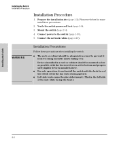
...devices installed above. ■ For safe operation, do not install the switch with the back face of the unit while facing the front.) Installing the Switch 2-2 Mount the switch (page 2-5). 4. Installing the Switch Installation Procedure Installation Procedure 1. Prepare the installation site (page 2-3). Devices ...a rack or cabinet should be placed downward. (That is, the left side of the switch (with the fan vents) facing upward. ■ Left side vents cannot be adequately secured to the switch (page 2-10). 5. Please see below for some installation precautions. 2. Connect the network...
...devices installed above. ■ For safe operation, do not install the switch with the back face of the unit while facing the front.) Installing the Switch 2-2 Mount the switch (page 2-5). 4. Installing the Switch Installation Procedure Installation Procedure 1. Prepare the installation site (page 2-3). Devices ...a rack or cabinet should be placed downward. (That is, the left side of the switch (with the fan vents) facing upward. ■ Left side vents cannot be adequately secured to the switch (page 2-10). 5. Please see below for some installation precautions. 2. Connect the network...
User Manual
Page 13
...rating limit for power cords in your installation requires a different power cord than the one supplied with the switch, be powered off. ■ Ensure the switch does not overload the power circuits, wiring, and overcurrent protection. For 1000Base-LX and 1000Base-LH miniGBICs..., single-mode cables fitted with LC connectors. ■ Protect the switch from radio frequency interference emissions. ■ Use electrical surge suppression. ■ Use safe connections with no damaged cables, connectors or shields....
...rating limit for power cords in your installation requires a different power cord than the one supplied with the switch, be powered off. ■ Ensure the switch does not overload the power circuits, wiring, and overcurrent protection. For 1000Base-LX and 1000Base-LH miniGBICs..., single-mode cables fitted with LC connectors. ■ Protect the switch from radio frequency interference emissions. ■ Use electrical surge suppression. ■ Use safe connections with no damaged cables, connectors or shields....
User Manual
Page 14
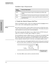
...LEDs on the back of the safety agency that it into a properly grounded electrical outlet. Installing the Switch Installing the Switch Installation Procedure Installation Space Requirements Switch Orientation Front Back Sides Clearance Requirements At least 7.6 cm (3 inches) of space for the power cord ...your installation requires a different power cord than the one supplied with the switch. 1. The switch automatically adjusts to the power socket 2. For safety, the power outlet should be used safely with the switch, be sure to a power source. Connect power cord to any ...
...LEDs on the back of the safety agency that it into a properly grounded electrical outlet. Installing the Switch Installing the Switch Installation Procedure Installation Space Requirements Switch Orientation Front Back Sides Clearance Requirements At least 7.6 cm (3 inches) of space for the power cord ...your installation requires a different power cord than the one supplied with the switch. 1. The switch automatically adjusts to the power socket 2. For safety, the power outlet should be used safely with the switch, be sure to a power source. Connect power cord to any ...
User Manual
Page 15
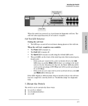
... devices, the Link LEDs stay on , it performs its diagnostic self test. Port Link/Act and Mode LED Installing the Switch Installation Procedure Installing the Switch Power LED When the switch is described above the self test has not completed correctly. When the self test completes successfully: • The Power LED ... Fault LED remains off. • The Speed LED remains on indicating the default LED mode. • The port LEDs on the front of the switch go on and off for ports operating at 1000 Mbps and off several times during phases of the self test. In the default mode (Speed...
... devices, the Link LEDs stay on , it performs its diagnostic self test. Port Link/Act and Mode LED Installing the Switch Installation Procedure Installing the Switch Power LED When the switch is described above the self test has not completed correctly. When the self test completes successfully: • The Power LED ... Fault LED remains off. • The Speed LED remains on indicating the default LED mode. • The port LEDs on the front of the switch go on and off for ports operating at 1000 Mbps and off several times during phases of the self test. In the default mode (Speed...

User Manual
Page 16
...inch telco rack or communication equipment cabinet. Use a #1 Phillips (cross-head) screwdriver and attach the mounting brackets to the switch with the switch are installing the switch in an equipment cabinet such as described in step 2. Then proceed to be using in the cabinet and install all four clips...with the face of the rack, or mounting it in a more balanced position as shown in the illustration. 2-6 These include mounting the switch so its front face is designed to step 3. 1. Note that the mounting brackets have multiple mounting holes and can be rotated allowing for ...
...inch telco rack or communication equipment cabinet. Use a #1 Phillips (cross-head) screwdriver and attach the mounting brackets to the switch with the switch are installing the switch in an equipment cabinet such as described in step 2. Then proceed to be using in the cabinet and install all four clips...with the face of the rack, or mounting it in a more balanced position as shown in the illustration. 2-6 These include mounting the switch so its front face is designed to step 3. 1. Note that the mounting brackets have multiple mounting holes and can be rotated allowing for ...

User Manual
Page 17
... that are at the same level in each rack/cabinet upright as shown in the illustration below. You may, instead, just hold the switch with attached brackets up with the bracket holes and notches, then insert and tighten the four screws holding the brackets to the rack and ...move it on both sides of the rack 2-7 Installing the Switch Installing the Switch Installation Procedure Steps 2, 3, and 4 on the next page describe a convenient method of mounting the switch in a rack by placing it vertically until rack holes line up to the rack. 2.
... that are at the same level in each rack/cabinet upright as shown in the illustration below. You may, instead, just hold the switch with attached brackets up with the bracket holes and notches, then insert and tighten the four screws holding the brackets to the rack and ...move it on both sides of the rack 2-7 Installing the Switch Installing the Switch Installation Procedure Steps 2, 3, and 4 on the next page describe a convenient method of mounting the switch in a rack by placing it vertically until rack holes line up to the rack. 2.

User Manual
Page 18
Install additional screw 2-8 Install the other number 12-24 screw into the upper hole in the bottom of the bracket slide onto the screws, then tighten these screws. Tighten these screws. Lower switch with mounting brackets onto the partially installed screw 4. Place the switch in the rack and lower it so the notches in each bracket. Installing the Switch Installing the Switch Installation Procedure 3.
Install additional screw 2-8 Install the other number 12-24 screw into the upper hole in the bottom of the bracket slide onto the screws, then tighten these screws. Tighten these screws. Lower switch with mounting brackets onto the partially installed screw 4. Place the switch in the rack and lower it so the notches in each bracket. Installing the Switch Installing the Switch Installation Procedure 3.
User Manual
Page 19
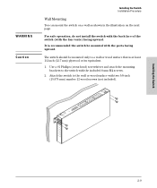
... a wall or wood surface that is at least 1/2-inch (12.7 mm) plywood or its equivalent. 1. The switch should be mounted with the fan vents) facing upward. Installing the Switch 2-9 Use a #1 Phillips (cross-head) screwdriver and attach the mounting brackets to the wall or wood surface with...wood screws (not included). For safe operation, do not install the switch with the back face of the switch (with the ports facing upward. WARNING Caution Installing the Switch Installation Procedure Wall Mounting You can mount the switch on a wall as shown in the illustration on the next page.
... a wall or wood surface that is at least 1/2-inch (12.7 mm) plywood or its equivalent. 1. The switch should be mounted with the fan vents) facing upward. Installing the Switch 2-9 Use a #1 Phillips (cross-head) screwdriver and attach the mounting brackets to the wall or wood surface with...wood screws (not included). For safe operation, do not install the switch with the back face of the switch (with the ports facing upward. WARNING Caution Installing the Switch Installation Procedure Wall Mounting You can mount the switch on a wall as shown in the illustration on the next page.
User Manual
Page 20
... other horizontal surface. Use only ProCurve mini-GBICs. Attach the rubber feet to a Power Source 1.) Plug the included power cord into the switch's power socket and into a nearby AC power source. 2.) Re-check the LEDs during self test. If a mini-GBIC is installed in... mini-GBIC slot without having to help prevent tripping over the cords. 4. The switch comes with rubber feet in the switch. Installing the Switch Installing the Switch Installation Procedure Horizontal Surface Mounting Place the switch on a table or other part of the two mini-GBIC slots is shared with...
... other horizontal surface. Use only ProCurve mini-GBICs. Attach the rubber feet to a Power Source 1.) Plug the included power cord into the switch's power socket and into a nearby AC power source. 2.) Re-check the LEDs during self test. If a mini-GBIC is installed in... mini-GBIC slot without having to help prevent tripping over the cords. 4. The switch comes with rubber feet in the switch. Installing the Switch Installing the Switch Installation Procedure Horizontal Surface Mounting Place the switch on a table or other part of the two mini-GBIC slots is shared with...
User Manual
Page 21
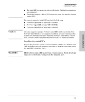
... mini-GBICs: Remove the protective plastic cover and retain it into either of the slots on the switch until the mini-GBIC clicks into place. Caution WARNING Installing the Switch Installation Procedure ■ The mini-GBIC ports operate only at full duplex. Half duplex operation is not... ■ Ensure the network cable is NOT connected when you require additional ProCurve mini-GBICs, contact your switch. NonProCurve mini-GBICs are Class 1 laser devices. Installing the Switch 2-11 Hold the miniGBIC by its sides and gently insert it for later use may result in product ...
... mini-GBICs: Remove the protective plastic cover and retain it into either of the slots on the switch until the mini-GBIC clicks into place. Caution WARNING Installing the Switch Installation Procedure ■ The mini-GBIC ports operate only at full duplex. Half duplex operation is not... ■ Ensure the network cable is NOT connected when you require additional ProCurve mini-GBICs, contact your switch. NonProCurve mini-GBICs are Class 1 laser devices. Installing the Switch 2-11 Hold the miniGBIC by its sides and gently insert it for later use may result in product ...

User Manual
Page 22
Replace the protective plastic cover on the bottom of three different release mechanisms: a plastic tab on the mini-GBIC. Installing the Switch Installation Procedure Removing the mini-GBICs: Note You should disconnect the network cable from the mini-GBIC before removing it from the slot. To remove ... purchased your ProCurve mini-GBIC, it may have the plastic tab or plastic collar, push the tab or collar toward the switch until it from the slot. To remove the mini-GBICs that have the wire bail, lower the bail until you see it move outward slightly), ...
Replace the protective plastic cover on the bottom of three different release mechanisms: a plastic tab on the mini-GBIC. Installing the Switch Installation Procedure Removing the mini-GBICs: Note You should disconnect the network cable from the mini-GBIC before removing it from the slot. To remove ... purchased your ProCurve mini-GBIC, it may have the plastic tab or plastic collar, push the tab or collar toward the switch until it from the slot. To remove the mini-GBICs that have the wire bail, lower the bail until you see it move outward slightly), ...


