User Manual
Page 7
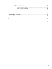
Using Windows system restore points 60 When to create restore points 60 Create a system restore point 60 Restore to a previous date and time 60 8 Power cord set requirements ...61 Requirements for all countries ...61 Requirements for specific countries and regions 61 9 Recycling ...63 Index ...64 vii
Using Windows system restore points 60 When to create restore points 60 Create a system restore point 60 Restore to a previous date and time 60 8 Power cord set requirements ...61 Requirements for all countries ...61 Requirements for specific countries and regions 61 9 Recycling ...63 Index ...64 vii
User Manual
Page 24
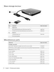
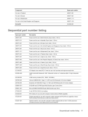
... use only in India 613149-001 65-W PFC RC V 3-wire AC adapter (non-smart) for use in all countries and regions except India 613149-001 Power cord (3-pin, black, 1.83-m): For use in Australia 490371-011 For use in Italy 490371-061 For use in Japan 490371-291 For use in North...
... use only in India 613149-001 65-W PFC RC V 3-wire AC adapter (non-smart) for use in all countries and regions except India 613149-001 Power cord (3-pin, black, 1.83-m): For use in Australia 490371-011 For use in Italy 490371-061 For use in Japan 490371-291 For use in North...
User Manual
Page 25
..., black, 1.83-m) Power cord for use in Australia (3-pin, black, 1.83-m) Power cord for use in Europe (3-pin, black, 1.83-m) Power cord for use in the United Kingdom and Singapore (3-pin, black, 1.83-m) Power cord for use in Italy (3-pin, black, 1.83-m) Power cord for use in Switzerland (3-pin, black, 1.83-m) Power cord for use in Thailand (3-pin, black, 1.83-m) Power cord for use...
..., black, 1.83-m) Power cord for use in Australia (3-pin, black, 1.83-m) Power cord for use in Europe (3-pin, black, 1.83-m) Power cord for use in the United Kingdom and Singapore (3-pin, black, 1.83-m) Power cord for use in Italy (3-pin, black, 1.83-m) Power cord for use in Switzerland (3-pin, black, 1.83-m) Power cord for use in Thailand (3-pin, black, 1.83-m) Power cord for use...
User Manual
Page 33
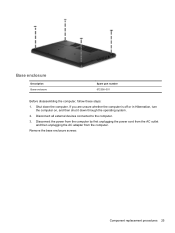
If you are unsure whether the computer is off or in Hibernation, turn the computer on, and then shut it down the computer. Disconnect all external devices connected to the computer. 3. Remove the base enclosure screws: Component replacement procedures 25 Shut down through the operating system. 2. Disconnect the power from the computer by first unplugging the power cord from the AC outlet and then unplugging the AC adapter from the computer. Base enclosure Description Base enclosure Spare part number 672356-001 Before disassembling the computer, follow these steps: 1.
If you are unsure whether the computer is off or in Hibernation, turn the computer on, and then shut it down the computer. Disconnect all external devices connected to the computer. 3. Remove the base enclosure screws: Component replacement procedures 25 Shut down through the operating system. 2. Disconnect the power from the computer by first unplugging the power cord from the AC outlet and then unplugging the AC adapter from the computer. Base enclosure Description Base enclosure Spare part number 672356-001 Before disassembling the computer, follow these steps: 1.
User Manual
Page 35
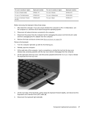
... swing the keyboard forward slightly, and disconnect the keyboard's zero insertion force (ZIF) cable (1). 6. Shut down through the operating system. 2. Remove the keyboard: 1. Disconnect the power from the computer by first unplugging the power cord from the AC outlet and then unplugging the AC adapter from the computer. 4.
... swing the keyboard forward slightly, and disconnect the keyboard's zero insertion force (ZIF) cable (1). 6. Shut down through the operating system. 2. Remove the keyboard: 1. Disconnect the power from the computer by first unplugging the power cord from the AC outlet and then unplugging the AC adapter from the computer. 4.
User Manual
Page 36
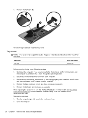
Top cover NOTE: The top cover spare part kit includes the power button board and cable and the TouchPad and cable. Remove the base enclosure screws (see Base enclosure on the replacement top cover. When replacing the ... computer. 4. Description Top cover Spare part number 672357-001 Before removing the top cover, follow these steps: 1. If you . 2. Disconnect the power from the computer by first unplugging the power cord from the AC outlet and then unplugging the AC adapter from the defective top cover and installed on page 25). 5. Open the...
Top cover NOTE: The top cover spare part kit includes the power button board and cable and the TouchPad and cable. Remove the base enclosure screws (see Base enclosure on the replacement top cover. When replacing the ... computer. 4. Description Top cover Spare part number 672357-001 Before removing the top cover, follow these steps: 1. If you . 2. Disconnect the power from the computer by first unplugging the power cord from the AC outlet and then unplugging the AC adapter from the defective top cover and installed on page 25). 5. Open the...
User Manual
Page 38
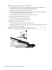
...If you . 2. Remove the top cover (see Battery on page 28). 7. Disconnect the battery cable (see Top cover on page 32). Remove the Power button board (2). Disconnect the power from the computer by first unplugging the power cord from the AC outlet and then unplugging the AC adapter from the computer. 4. NOTE: The... Power button board's cable is off or in Hibernation, turn the computer on, and then shut it down through the operating system. 2. Remove ...
...If you . 2. Remove the top cover (see Battery on page 28). 7. Disconnect the battery cable (see Top cover on page 32). Remove the Power button board (2). Disconnect the power from the computer by first unplugging the power cord from the AC outlet and then unplugging the AC adapter from the computer. 4. NOTE: The... Power button board's cable is off or in Hibernation, turn the computer on, and then shut it down through the operating system. 2. Remove ...
User Manual
Page 39
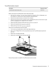
... back edge toward you are unsure whether the computer is off or in Hibernation, turn the computer on page 26). 6. Disconnect the power from the computer by first unplugging the power cord from the AC outlet and then unplugging the AC adapter from the computer. 4. Remove the TouchPad button board and cable: 1. Turn...
... back edge toward you are unsure whether the computer is off or in Hibernation, turn the computer on page 26). 6. Disconnect the power from the computer by first unplugging the power cord from the AC outlet and then unplugging the AC adapter from the computer. 4. Remove the TouchPad button board and cable: 1. Turn...
User Manual
Page 40
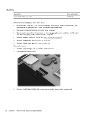
... Before removing the battery, follow these steps: 1. Remove the keyboard (see Base enclosure on page 26). 6. Remove the battery: 1. Disconnect the power from the computer by first unplugging the power cord from the AC outlet and then unplugging the AC adapter from the computer. 4. Shut down through the operating system. 2. Remove the base...
... Before removing the battery, follow these steps: 1. Remove the keyboard (see Base enclosure on page 26). 6. Remove the battery: 1. Disconnect the power from the computer by first unplugging the power cord from the AC outlet and then unplugging the AC adapter from the computer. 4. Shut down through the operating system. 2. Remove the base...
User Manual
Page 42
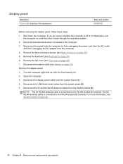
...: 1. Disconnect the USB/Audio board cable from the computer. 4. For more information, see Top cover on page 28). 7. Disconnect the power from the computer by first unplugging the power cord from the AC outlet and then unplugging the AC adapter from the system board (2). 5. Remove the display panel: 1. Open the computer. ... Battery on page 32). Disconnect the #1 and #2 WLAN antenna cables from the system board (1). 4. Shut down through the operating system. 2. Display panel Description 13.3-in Hibernation, turn the computer on, and then shut it down the computer. If you . 2.
...: 1. Disconnect the USB/Audio board cable from the computer. 4. For more information, see Top cover on page 28). 7. Disconnect the power from the computer by first unplugging the power cord from the AC outlet and then unplugging the AC adapter from the system board (2). 5. Remove the display panel: 1. Open the computer. ... Battery on page 32). Disconnect the #1 and #2 WLAN antenna cables from the system board (1). 4. Shut down through the operating system. 2. Display panel Description 13.3-in Hibernation, turn the computer on, and then shut it down the computer. If you . 2.
User Manual
Page 44
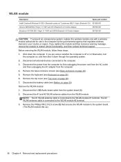
...: To prevent an unresponsive system, replace the wireless module only with a wireless module authorized for use in the computer by first unplugging the power cord from the AC outlet and then unplugging the AC adapter from the computer. 4. Remove the top cover (see Keyboard on , and then...unsure whether the computer is connected to the system board. (The WLAN module tilts up.) 36 Chapter 4 Removal and replacement procedures Disconnect the power from the computer by the governmental agency that secures the WLAN module to the WLAN module #2 terminal. 3. Before removing the WLAN module, ...
...: To prevent an unresponsive system, replace the wireless module only with a wireless module authorized for use in the computer by first unplugging the power cord from the AC outlet and then unplugging the AC adapter from the computer. 4. Remove the top cover (see Keyboard on , and then...unsure whether the computer is connected to the system board. (The WLAN module tilts up.) 36 Chapter 4 Removal and replacement procedures Disconnect the power from the computer by the governmental agency that secures the WLAN module to the WLAN module #2 terminal. 3. Before removing the WLAN module, ...
User Manual
Page 45
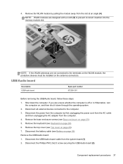
... on page 28). 7. Shut down through the operating system. 2. Disconnect the USB/Audio board cable from the computer. 4. Disconnect the power from the computer by pulling the module away from the slot at an angle (4). Remove the base enclosure screws (see Top cover on ...the antenna connectors. Disconnect the Phillips PM 2.0x2.0 screw securing the USB/Audio board (2). 4. Remove the WLAN module by first unplugging the power cord from the AC outlet and then unplugging the AC adapter from the system board (1) 2. Component replacement procedures 37 Remove the USB/Audio board...
... on page 28). 7. Shut down through the operating system. 2. Disconnect the USB/Audio board cable from the computer. 4. Disconnect the power from the computer by pulling the module away from the slot at an angle (4). Remove the base enclosure screws (see Top cover on ...the antenna connectors. Disconnect the Phillips PM 2.0x2.0 screw securing the USB/Audio board (2). 4. Remove the WLAN module by first unplugging the power cord from the AC outlet and then unplugging the AC adapter from the system board (1) 2. Component replacement procedures 37 Remove the USB/Audio board...
User Manual
Page 47
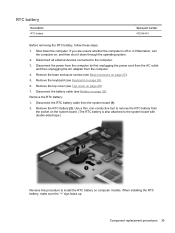
... whether the computer is also attached to the system board with double-sided tape.) Reverse this procedure to the computer. 3. Disconnect the power from the computer by first unplugging the power cord from the AC outlet and then unplugging the AC adapter from the system board (1). 2. Disconnect all external devices connected to install...
... whether the computer is also attached to the system board with double-sided tape.) Reverse this procedure to the computer. 3. Disconnect the power from the computer by first unplugging the power cord from the AC outlet and then unplugging the AC adapter from the system board (1). 2. Disconnect all external devices connected to install...
User Manual
Page 48
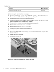
... hard drive. 40 Chapter 4 Removal and replacement procedures Reverse this procedure to the computer. (The hard drive tilts up.) 2. Disconnect the power from the computer by first unplugging the power cord from the AC outlet and then unplugging the AC adapter from the computer. 4. Remove the hard drive: 1. Disconnect all external devices connected...
... hard drive. 40 Chapter 4 Removal and replacement procedures Reverse this procedure to the computer. (The hard drive tilts up.) 2. Disconnect the power from the computer by first unplugging the power cord from the AC outlet and then unplugging the AC adapter from the computer. 4. Remove the hard drive: 1. Disconnect all external devices connected...
User Manual
Page 49
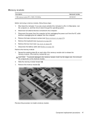
... the keyboard (see Base enclosure on page 25). 5. Spread the retaining tabs (1) on , and then shut it by first unplugging the power cord from the AC outlet and then unplugging the AC adapter from the computer. 4. Do not touch the components on page 28). 7. If you... Description 4-GB memory module (PC3, 10600, 1333-MHz) Spare part number 641369-001 Before removing a memory module, follow these steps: 1. Disconnect the power from the computer by the edges only. Reverse this procedure to the memory module, hold it down the computer. Remove the memory module (3). Remove the...
... the keyboard (see Base enclosure on page 25). 5. Spread the retaining tabs (1) on , and then shut it by first unplugging the power cord from the AC outlet and then unplugging the AC adapter from the computer. 4. Do not touch the components on page 28). 7. If you... Description 4-GB memory module (PC3, 10600, 1333-MHz) Spare part number 641369-001 Before removing a memory module, follow these steps: 1. Disconnect the power from the computer by the edges only. Reverse this procedure to the memory module, hold it down the computer. Remove the memory module (3). Remove the...
User Manual
Page 50
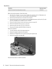
... cover on page 25). 5. Remove the speakers: 1. If you . 2. Remove the top cover (see Base enclosure on page 28). 7. Disconnect the power from the computer by first unplugging the power cord from the AC outlet and then unplugging the AC adapter from the clips (1). 3. Disconnect the battery cable (see Keyboard on page 32...
... cover on page 25). 5. Remove the speakers: 1. If you . 2. Remove the top cover (see Base enclosure on page 28). 7. Disconnect the power from the computer by first unplugging the power cord from the AC outlet and then unplugging the AC adapter from the clips (1). 3. Disconnect the battery cable (see Keyboard on page 32...
User Manual
Page 51
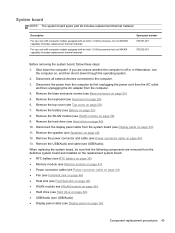
... cover on page 25). 5. Remove the USB/Audio and cable (see Display panel on page 34). 11. Disconnect the power from the computer by first unplugging the power cord from the AC outlet and then unplugging the AC adapter from the system board (see USB/Audio). Remove the top cover ...(see Base enclosure on page 28). 7. Remove the hard drive (see Power connector cable on page 40). 10. Remove the power connector and cable (see Hard drive on page 44). 13...
... cover on page 25). 5. Remove the USB/Audio and cable (see Display panel on page 34). 11. Disconnect the power from the computer by first unplugging the power cord from the AC outlet and then unplugging the AC adapter from the system board (see USB/Audio). Remove the top cover ...(see Base enclosure on page 28). 7. Remove the hard drive (see Power connector cable on page 40). 10. Remove the power connector and cable (see Hard drive on page 44). 13...
User Manual
Page 53
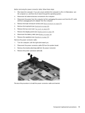
Disconnect all external devices connected to install the power connector cable and bracket. Disconnect the power from the computer by first unplugging the power cord from the AC outlet and then unplugging the AC adapter from the power connector. 4. If you . 2. Remove the display panel (see Keyboard ... page 28). 7. Remove the double-sided tape (2) from the computer. 4. Shut down through the operating system. 2. Before removing the power connector cable, follow these steps: 1. Remove the base enclosure screws (see Top cover on page 34). 8. Turn the computer, with the...
Disconnect all external devices connected to install the power connector cable and bracket. Disconnect the power from the computer by first unplugging the power cord from the AC outlet and then unplugging the AC adapter from the power connector. 4. If you . 2. Remove the display panel (see Keyboard ... page 28). 7. Remove the double-sided tape (2) from the computer. 4. Shut down through the operating system. 2. Before removing the power connector cable, follow these steps: 1. Remove the base enclosure screws (see Top cover on page 34). 8. Turn the computer, with the...
User Manual
Page 54
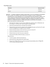
...Top cover on page 28). 7. Turn the computer, with the front toward you are affected by high external temperatures, system power consumption, power management/battery conservation configurations, battery fast charging, and software requirements. Remove the 4 Phillips PM 2.0×3.0 screws securing the heat ... screws securing the fan (3). 46 Chapter 4 Removal and replacement procedures If you . 2. The fan is controlled by first unplugging the power cord from the AC outlet and then unplugging the AC adapter from the system board. 3. Exhaust air is designed to the computer. 3....
...Top cover on page 28). 7. Turn the computer, with the front toward you are affected by high external temperatures, system power consumption, power management/battery conservation configurations, battery fast charging, and software requirements. Remove the 4 Phillips PM 2.0×3.0 screws securing the heat ... screws securing the fan (3). 46 Chapter 4 Removal and replacement procedures If you . 2. The fan is controlled by first unplugging the power cord from the AC outlet and then unplugging the AC adapter from the system board. 3. Exhaust air is designed to the computer. 3....
User Manual
Page 59
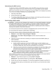
... During the download and installation, follow these steps: a. Identify the BIOS update that are displayed, follow these instructions: Do not disconnect power from the AC outlet. Make a note of damage to the computer or an unsuccessful installation, download and install a BIOS update only ...Do not insert, remove, connect, or disconnect any instructions that is typically Local Disk (C:). 3. Windows 7-Open Windows Explorer by unplugging the power cord from the computer by selecting Start > Computer. You will need to know the version of the path to select Exit > Exit Discarding...
... During the download and installation, follow these steps: a. Identify the BIOS update that are displayed, follow these instructions: Do not disconnect power from the AC outlet. Make a note of damage to the computer or an unsuccessful installation, download and install a BIOS update only ...Do not insert, remove, connect, or disconnect any instructions that is typically Local Disk (C:). 3. Windows 7-Open Windows Explorer by unplugging the power cord from the computer by selecting Start > Computer. You will need to know the version of the path to select Exit > Exit Discarding...

