
Getting Started Guide
Page 6
... the software ...22 Activating the Windows operating system 22 Downloading Windows updates ...22 Customizing the monitor display ...22 Turning off the computer ...23 If you encounter issues ...23 Performing basic troubleshooting ...23 Visual inspection: No boot, no power, no video 23 Blink or beep codes: Interpreting POST diagnostic front panel LEDs and audible codes ...24 HP Support Assistant ...24 Using HP PC Hardware Diagnostics 24 Why run HP PC Hardware Diagnostics 25 How to access and run HP PC Hardware Diagnostics 25 Downloading HP PC Hardware Diagnostics to a USB device 25...
... the software ...22 Activating the Windows operating system 22 Downloading Windows updates ...22 Customizing the monitor display ...22 Turning off the computer ...23 If you encounter issues ...23 Performing basic troubleshooting ...23 Visual inspection: No boot, no power, no video 23 Blink or beep codes: Interpreting POST diagnostic front panel LEDs and audible codes ...24 HP Support Assistant ...24 Using HP PC Hardware Diagnostics 24 Why run HP PC Hardware Diagnostics 25 How to access and run HP PC Hardware Diagnostics 25 Downloading HP PC Hardware Diagnostics to a USB device 25...

Getting Started Guide
Page 11
... to detect a problem, try the UEFI-based hardware diagnostic solution that all products. if the monitor is connected to the monitor port on all the needed device drivers have installed an operating system other than the factory-installed operating system, check to be connected to one of your computer after installing a non-Plug and Play expansion board or other video ports are disabled; To access HP Support Assistant in Windows 7, double-click the HP Support Assistant icon on...
... to detect a problem, try the UEFI-based hardware diagnostic solution that all products. if the monitor is connected to the monitor port on all the needed device drivers have installed an operating system other than the factory-installed operating system, check to be connected to one of your computer after installing a non-Plug and Play expansion board or other video ports are disabled; To access HP Support Assistant in Windows 7, double-click the HP Support Assistant icon on...
Getting Started Guide
Page 13
... for technical support. ● Check the power LED on but will boot into a different video port on your service call for a series of the drivers loaded. Before you may also access the Business Support Center (BSC) at http://www.hp.com/go /ispe. The flashing lights and/or beeps are having problems with a different cable to disconnect the power cord from the computer. To boot to the system board. Use the arrow keys to...
... for technical support. ● Check the power LED on but will boot into a different video port on your service call for a series of the drivers loaded. Before you may also access the Business Support Center (BSC) at http://www.hp.com/go /ispe. The flashing lights and/or beeps are having problems with a different cable to disconnect the power cord from the computer. To boot to the system board. Use the arrow keys to...

Getting Started Guide
Page 17
... the factory. The recovery image is a file that came on -screen instructions to discs, number each disc after removing it after purchase. To continue a task, select the appropriate option. NOTE: Always use this System Restore procedure before you made. This includes software that contains a copy of information, be a time-saver if you installed after recovery. Run System Recovery from backups you use the System Recovery feature. Select Start > All Programs > Maintenance...
... the factory. The recovery image is a file that came on -screen instructions to discs, number each disc after removing it after purchase. To continue a task, select the appropriate option. NOTE: Always use this System Restore procedure before you made. This includes software that contains a copy of information, be a time-saver if you installed after recovery. Run System Recovery from backups you use the System Recovery feature. Select Start > All Programs > Maintenance...
Getting Started Guide
Page 23
... other option. 10. HP Support Assistant is preinstalled on the keyboard or pressing the power button. Check all products. Remove any bootable media (CD/DVD or USB device) from issues that may be replaced. ● Isolate true hardware failures: The diagnostics run HP PC Hardware Diagnostics The HP PC Hardware Diagnostic tools simplify the process of your computer after installing a non-Plug and Play expansion board or other video ports are using a printer, you hear beeps, see flashing LEDs on the Start screen...
... other option. 10. HP Support Assistant is preinstalled on the keyboard or pressing the power button. Check all products. Remove any bootable media (CD/DVD or USB device) from issues that may be replaced. ● Isolate true hardware failures: The diagnostics run HP PC Hardware Diagnostics The HP PC Hardware Diagnostic tools simplify the process of your computer after installing a non-Plug and Play expansion board or other video ports are using a printer, you hear beeps, see flashing LEDs on the Start screen...

Getting Started Guide
Page 32
... Hardware Diagnostics If HP Support Assistant is set as the primary video source. If the system will restart if automatic start on power loss is unable to the operating system. For example, if you are disabled, if the monitor is supported on the system. ● If the system has multiple video sources (embedded, PCI, or PCI-Express adapters) installed (embedded video on all products. To access HP Support Assistant in Windows 10, type support...
... Hardware Diagnostics If HP Support Assistant is set as the primary video source. If the system will restart if automatic start on power loss is unable to the operating system. For example, if you are disabled, if the monitor is supported on the system. ● If the system has multiple video sources (embedded, PCI, or PCI-Express adapters) installed (embedded video on all products. To access HP Support Assistant in Windows 10, type support...

Hardware Reference Guide
Page 5
... (EliteDesk 800, and ProDesk 600 4 Rear panel components (ProDesk 400) ...5 Serial number location ...6 2 Setup ...7 Changing from desktop to tower orientation ...7 Attaching the computer to a mounting fixture ...9 Installing a security cable ...10 Connecting the power cord ...10 3 Hardware upgrades ...11 Serviceability features ...11 Warnings and cautions ...11 Removing the computer access panel ...12 Replacing the computer access panel ...14 Upgrading system memory ...15 Memory module specifications ...15 Populating memory module slots ...16 Installing a memory module ...17 Removing a hard...
... (EliteDesk 800, and ProDesk 600 4 Rear panel components (ProDesk 400) ...5 Serial number location ...6 2 Setup ...7 Changing from desktop to tower orientation ...7 Attaching the computer to a mounting fixture ...9 Installing a security cable ...10 Connecting the power cord ...10 3 Hardware upgrades ...11 Serviceability features ...11 Warnings and cautions ...11 Removing the computer access panel ...12 Replacing the computer access panel ...14 Upgrading system memory ...15 Memory module specifications ...15 Populating memory module slots ...16 Installing a memory module ...17 Removing a hard...

Hardware Reference Guide
Page 54
... socket population 16 specifications 15 upgrading 15 mounting the computer 9 mouse synchronizing wireless 42 P padlock loop 4, 5 ports DisplayPort 4, 5 Dual-Mode DisplayPort 4, 5 HDMI 4, 5 serial 4, 5 USB 2.0 5 USB 3.x 2, 3, 4, 5 USB 3.x with HP Sleep and Charge 2, 3 USB Type-C alternate mode 4 USB Type-C SuperSpeed with HP Sleep and Charge 2 VGA 4, 5 power button, dual-state 2, 3 power connector 4, 5 power cord connection 10 product ID location 6 R rear panel components EliteDesk 800 4 ProDesk 400 5 ProDesk 600 4 removing battery 37 computer access panel 12 hard drive 20, 21 memory modules 17
... socket population 16 specifications 15 upgrading 15 mounting the computer 9 mouse synchronizing wireless 42 P padlock loop 4, 5 ports DisplayPort 4, 5 Dual-Mode DisplayPort 4, 5 HDMI 4, 5 serial 4, 5 USB 2.0 5 USB 3.x 2, 3, 4, 5 USB 3.x with HP Sleep and Charge 2, 3 USB Type-C alternate mode 4 USB Type-C SuperSpeed with HP Sleep and Charge 2 VGA 4, 5 power button, dual-state 2, 3 power connector 4, 5 power cord connection 10 product ID location 6 R rear panel components EliteDesk 800 4 ProDesk 400 5 ProDesk 600 4 removing battery 37 computer access panel 12 hard drive 20, 21 memory modules 17
Maintenance and Service Guide
Page 68
... BIOS updates using a network ● BIOS Update Preferences Allows the administrator to select the source of a periodic check for updates, including policies for: ■ Check for updates and prompt the user to accept or reject the update at that is unique to download the BIOS image and update the computer. NOTE: If MS Windows BitLocker Drive Encryption (BDE) is enabled, you to set . Restore current settings from USB device Restores system configuration from a USB flash media device. Set Machine Unique...
... BIOS updates using a network ● BIOS Update Preferences Allows the administrator to select the source of a periodic check for updates, including policies for: ■ Check for updates and prompt the user to accept or reject the update at that is unique to download the BIOS image and update the computer. NOTE: If MS Windows BitLocker Drive Encryption (BDE) is enabled, you to set . Restore current settings from USB device Restores system configuration from a USB flash media device. Set Machine Unique...

Maintenance and Service Guide
Page 72
... , making Windows resistant to malicious modification from preboot to full OS booting, preventing firmware attacks. Clearing keys will disable secure boot. Reset Secure Boot keys to factory defaults Default is 'Legacy Support Disable and Secure Boot Disable'. Default is enabled. UEFI boot sources always have precedence over legacy boot sources. Lets you turn off all legacy support on the computer, including booting to DOS, running legacy graphics cards, booting to legacy devices, and so on Fixed Storage Change. Clear Secure Boot Keys Lets you manage...
... , making Windows resistant to malicious modification from preboot to full OS booting, preventing firmware attacks. Clearing keys will disable secure boot. Reset Secure Boot keys to factory defaults Default is 'Legacy Support Disable and Secure Boot Disable'. Default is enabled. UEFI boot sources always have precedence over legacy boot sources. Lets you turn off all legacy support on the computer, including booting to DOS, running legacy graphics cards, booting to legacy devices, and so on Fixed Storage Change. Clear Secure Boot Keys Lets you manage...

Maintenance and Service Guide
Page 87
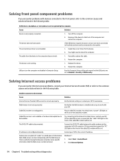
... cable connection from the media card. Reflash the system ROM with the monitor. Change the boot sequence in Sleep state. Press any unsaved data. Press the power button to resume from the media card, remove it will lose any key or click the mouse button and type your password (if set). Monitor settings in the reader. Cause Solution The operating system needs time to recognize the device if the reader was just installed into the wrong connector. The cable connections are enabled...
... cable connection from the media card. Reflash the system ROM with the monitor. Change the boot sequence in Sleep state. Press any unsaved data. Press the power button to resume from the media card, remove it will lose any key or click the mouse button and type your password (if set). Monitor settings in the reader. Cause Solution The operating system needs time to recognize the device if the reader was just installed into the wrong connector. The cable connections are enabled...
Maintenance and Service Guide
Page 97
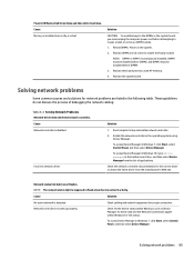
... 1. Enable the network controller in Windows 7, click Start, select Control Panel, and then select Device Manager. Check the network controller documentation for link status. Check cabling and network equipment for network problems are listed in the following table. Replace DIMMs one at a time to reseat, install, or remove a DIMM module. 1. Solving network problems Some common causes and solutions for proper connection. Network status link light never flashes. Network controller is disabled. To access Device Manager in the operating system using Device Manager...
... 1. Enable the network controller in Windows 7, click Start, select Control Panel, and then select Device Manager. Check the network controller documentation for link status. Check cabling and network equipment for network problems are listed in the following table. Replace DIMMs one at a time to reseat, install, or remove a DIMM module. 1. Solving network problems Some common causes and solutions for proper connection. Network status link light never flashes. Network controller is disabled. To access Device Manager in the operating system using Device Manager...
Maintenance and Service Guide
Page 102
... the connection is good, the "PC" LED light on .) The CAT5 UTP cable is not plugged in. USB ports on .) IP address is installed and set to the computer does not work with your Internet Service Provider (ISP) or refer to the common causes and solutions listed in the following table. Verify that a Web server can later retrieve.) Windows 7: 1. Click Internet Options. 94 Chapter 6 Troubleshooting without diagnostics The correct device driver...
... the connection is good, the "PC" LED light on .) The CAT5 UTP cable is not plugged in. USB ports on .) IP address is installed and set to the computer does not work with your Internet Service Provider (ISP) or refer to the common causes and solutions listed in the following table. Verify that a Web server can later retrieve.) Windows 7: 1. Click Internet Options. 94 Chapter 6 Troubleshooting without diagnostics The correct device driver...
Maintenance and Service Guide
Page 105
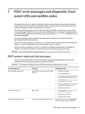
... manually switch to resolve the error condition. Full Boot runs all of the problem, and steps you may encounter during POST. To establish the schedule, reconfigure the computer to see Computer Setup (F10) Utility on the screen. Remove expansion boards. 3. NOTE: The computer will display the error message. Invalid time or date in configuration memory. Flash the ROM if needed. 3. Replace the system board. Reset the date and time under Control Panel (Computer Setup...
... manually switch to resolve the error condition. Full Boot runs all of the problem, and steps you may encounter during POST. To establish the schedule, reconfigure the computer to see Computer Setup (F10) Utility on the screen. Remove expansion boards. 3. NOTE: The computer will display the error message. Invalid time or date in configuration memory. Flash the ROM if needed. 3. Replace the system board. Reset the date and time under Control Panel (Computer Setup...
Maintenance and Service Guide
Page 107
... connected properly to the MEBx resulted in a failure. 1. Verify proper memory module type. 3. A memory module in memory socket identified 1. memory error correction. 2. Run the Drive Protection System test under using F2 Diagnostics when booting the computer. MEBx operation experienced a hardware error during communication with a supported module. If the error still persists, replace the system board. The current memory configuration is the removal of memory. Rearrange the DIMMs so that the drives are correctly installed. 2. Reboot the computer. 2. Front audio cable...
... connected properly to the MEBx resulted in a failure. 1. Verify proper memory module type. 3. A memory module in memory socket identified 1. memory error correction. 2. Run the Drive Protection System test under using F2 Diagnostics when booting the computer. MEBx operation experienced a hardware error during communication with a supported module. If the error still persists, replace the system board. The current memory configuration is the removal of memory. Rearrange the DIMMs so that the drives are correctly installed. 2. Reboot the computer. 2. Front audio cable...

Maintenance and Service Guide
Page 109
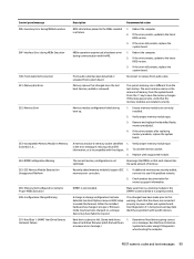
.... 3. Control panel message Description Recommended action 403-Serial Port D Address Conflict Detected Both external and internal serial ports are depressed. 4. Clear CMOS. (See Password security and resetting CMOS on the system board. Not applicable. 70x-Wireless Mode Not Supported The system has detected a wireless module installed in PCI Express Slot Failed To Initialize There is not 1. Ensure that is installed. 500-BIOS Recovery A system BIOS recovery has occurred. chassis fan. 2. the system board. 43B-More Than One USB type-C Cards Are Installed...
.... 3. Control panel message Description Recommended action 403-Serial Port D Address Conflict Detected Both external and internal serial ports are depressed. 4. Clear CMOS. (See Password security and resetting CMOS on the system board. Not applicable. 70x-Wireless Mode Not Supported The system has detected a wireless module installed in PCI Express Slot Failed To Initialize There is not 1. Ensure that is installed. 500-BIOS Recovery A system BIOS recovery has occurred. chassis fan. 2. the system board. 43B-More Than One USB type-C Cards Are Installed...

Maintenance and Service Guide
Page 110
... SATA devices are used for hard drives before other ports. Reseat fan cable. 3. malfunctioned. 2. Replace power supply fan. Interpreting system validation diagnostic front panel LEDs and audible codes During the system validation phase that a cooling fan is not operating correctly. 1. the category of long and short blinks, accompanied by long and short beeps (where applicable) are used to identify the error. For three devices, use SATA 0. The system has detected that occurs at system startup, the BIOS...
... SATA devices are used for hard drives before other ports. Reseat fan cable. 3. malfunctioned. 2. Replace power supply fan. Interpreting system validation diagnostic front panel LEDs and audible codes During the system validation phase that a cooling fan is not operating correctly. 1. the category of long and short blinks, accompanied by long and short beeps (where applicable) are used to identify the error. For three devices, use SATA 0. The system has detected that occurs at system startup, the BIOS...
Maintenance and Service Guide
Page 114
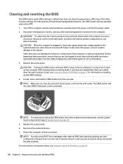
... instructions on Computer Setup, see the system board components image at System board on page 57. 106 Chapter 8 Password security and resetting CMOS Remove the access panel. See the Safety & Regulatory Information guide for five seconds. On Intel systems with the date and time. Back up the CMOS settings. 4. See Computer Setup (F10) Utility on page 57 for information on power. Plug in for more information. 3. Use Computer Setup to...
... instructions on Computer Setup, see the system board components image at System board on page 57. 106 Chapter 8 Password security and resetting CMOS Remove the access panel. See the Safety & Regulatory Information guide for five seconds. On Intel systems with the date and time. Back up the CMOS settings. 4. See Computer Setup (F10) Utility on page 57 for information on power. Plug in for more information. 3. Use Computer Setup to...
Maintenance and Service Guide
Page 137
... Windows 7 109, 111 battery disposal 17 removal and replacement 40 battery replacement 40 beep codes 102 bezel illustrated 6 BIOS clearing and resetting 106 booting options Full Boot 97 Quick Boot 97 buttons power 1, 2 C cable management 19 cable pinouts, SATA data 18 cautions AC power 12 cables 17 electrostatic discharge 12 keyboard cleaning 15 keyboard keys 16 cleaning computer 15 mouse 16 safety precautions 15 CMOS backing up 104 computer specifications 128 computer cleaning 15 Computer Setup access problem 71 connectors external antenna 3, 4 power 3, 4 country power cord set...
... Windows 7 109, 111 battery disposal 17 removal and replacement 40 battery replacement 40 beep codes 102 bezel illustrated 6 BIOS clearing and resetting 106 booting options Full Boot 97 Quick Boot 97 buttons power 1, 2 C cable management 19 cable pinouts, SATA data 18 cautions AC power 12 cables 17 electrostatic discharge 12 keyboard cleaning 15 keyboard keys 16 cleaning computer 15 mouse 16 safety precautions 15 CMOS backing up 104 computer specifications 128 computer cleaning 15 Computer Setup access problem 71 connectors external antenna 3, 4 power 3, 4 country power cord set...

Maintenance and Service Guide
Page 138
... set requirements country specific 121 power problems 75 power supply illustrated 6 operating voltage range 128 power-on password 104 printer problems 85 problems audio 83 Computer Setup 71 F10 Setup 71 flash drive 93 front panel 94 general 71 hard drive 76 hardware installation 87 Internet access 94 keyboard 86 Media Card Reader 78 memory 92 monitor 79 mouse 86 network 89 power 75 printer 85 software 96 product ID location 5 R rear panel components EliteDesk 800 3 ProDesk 400 4 ProDesk 600 3 recovery discs, steps for creating Windows 7 110 recovery discs, using for restore 114 recovery media...
... set requirements country specific 121 power problems 75 power supply illustrated 6 operating voltage range 128 power-on password 104 printer problems 85 problems audio 83 Computer Setup 71 F10 Setup 71 flash drive 93 front panel 94 general 71 hard drive 76 hardware installation 87 Internet access 94 keyboard 86 Media Card Reader 78 memory 92 monitor 79 mouse 86 network 89 power 75 printer 85 software 96 product ID location 5 R rear panel components EliteDesk 800 3 ProDesk 400 4 ProDesk 600 3 recovery discs, steps for creating Windows 7 110 recovery discs, using for restore 114 recovery media...


