Maintenance and Service Guide
Page 8
... cover ...33 Battery ...36 Hard drive ...37 Solid-state drive ...38 Memory modules ...40 WLAN module ...42 WWAN module ...44 Keyboard ...46 6 Removal and replacement procedures for Authorized Service Provider parts 49 Component replacement procedures ...49 System board ...49 RTC battery ...52 Heat sink/fan assembly ...53 Fingerprint reader assembly ...55 TouchPad button board ...56 NFC module ...57 Smart card reader board ...58 Speaker assembly ...59 Display assembly ...59 7 Computer Setup (BIOS), TPM, and HP Sure Start in Windows 10 66 Using Computer Setup...
... cover ...33 Battery ...36 Hard drive ...37 Solid-state drive ...38 Memory modules ...40 WLAN module ...42 WWAN module ...44 Keyboard ...46 6 Removal and replacement procedures for Authorized Service Provider parts 49 Component replacement procedures ...49 System board ...49 RTC battery ...52 Heat sink/fan assembly ...53 Fingerprint reader assembly ...55 TouchPad button board ...56 NFC module ...57 Smart card reader board ...58 Speaker assembly ...59 Display assembly ...59 7 Computer Setup (BIOS), TPM, and HP Sure Start in Windows 10 66 Using Computer Setup...

Maintenance and Service Guide
Page 9
Creating HP Recovery media (select products only 73 Using Windows tools ...74 Restore and recovery ...75 Recovering using HP Recovery Manager 75 What you need to know before you get started 75 Using the HP Recovery partition (select products only 76 Using HP Recovery media to recover 76 Changing the computer boot order 77 Removing the HP Recovery partition (select products only 78 10 Specifications ...79 Input power ...79 Operating environment ...79 11 Power cord set requirements ...80 Requirements for all countries ...80 Requirements for specific countries and...
Creating HP Recovery media (select products only 73 Using Windows tools ...74 Restore and recovery ...75 Recovering using HP Recovery Manager 75 What you need to know before you get started 75 Using the HP Recovery partition (select products only 76 Using HP Recovery media to recover 76 Changing the computer boot order 77 Removing the HP Recovery partition (select products only 78 10 Specifications ...79 Input power ...79 Operating environment ...79 11 Power cord set requirements ...80 Requirements for all countries ...80 Requirements for specific countries and...

Maintenance and Service Guide
Page 13
... M.2 WWAN module ● HP It4120 LTE/EVDO/HSPA+ with GPS M.2 Supports no WWAN option External media cards SIM card reader Memory card reader (SD, SDHC, SDXC) Ports VGA USB 3.1 charging USB 3.1 USB Type-C DisplayPort RJ-45 Docking connector Audio-out (headphone)/audio-in (microphone) combo jack AC port Keyboard/pointing devices Keyboard: Dura keys, backlit, spill resistant with drain Spill resistant with drain TouchPad: Gestures enabled by default: two-finger scrolling, two-finger pinch-zoom Taps enabled by default On/off button Glass Power requirements...
... M.2 WWAN module ● HP It4120 LTE/EVDO/HSPA+ with GPS M.2 Supports no WWAN option External media cards SIM card reader Memory card reader (SD, SDHC, SDXC) Ports VGA USB 3.1 charging USB 3.1 USB Type-C DisplayPort RJ-45 Docking connector Audio-out (headphone)/audio-in (microphone) combo jack AC port Keyboard/pointing devices Keyboard: Dura keys, backlit, spill resistant with drain Spill resistant with drain TouchPad: Gestures enabled by default: two-finger scrolling, two-finger pinch-zoom Taps enabled by default On/off button Glass Power requirements...

Maintenance and Service Guide
Page 16
...: USB Type-C ports charge products such as a highperformance monitor or projector. WARNING! 2 External component identification Right Component (1) USB Type-C (charging) port (2) Dual-Mode DisplayPort (3) Memory card reader (4) Audio-out (headphone)/Audio-in (microphone) combo jack (5) USB 3.1 port (6) RJ-45 (network) jack/status lights 6 Chapter 2 External component identification Description Connects any USB device with a Type-C connector. Reads optional memory cards that store, manage, share, or access information. NOTE: When a device is connected to provide video...
...: USB Type-C ports charge products such as a highperformance monitor or projector. WARNING! 2 External component identification Right Component (1) USB Type-C (charging) port (2) Dual-Mode DisplayPort (3) Memory card reader (4) Audio-out (headphone)/Audio-in (microphone) combo jack (5) USB 3.1 port (6) RJ-45 (network) jack/status lights 6 Chapter 2 External component identification Description Connects any USB device with a Type-C connector. Reads optional memory cards that store, manage, share, or access information. NOTE: When a device is connected to provide video...

Maintenance and Service Guide
Page 18
Standard USB ports will not charge all USB devices or will charge using a low current. Left Component (1) Security cable slot (2) Vents (2) (3) External monitor port (4) USB 3.1 charging (powered) port (5) Smart card reader Description Attaches an optional security cable to cool internal components and prevent overheating. It is normal for the internal fan to cool internal components. Connects an optional USB device, such as a deterrent, but it may not prevent the computer from being mishandled or stolen. Supports optional smart cards. 8 Chapter 2 External component ...
Standard USB ports will not charge all USB devices or will charge using a low current. Left Component (1) Security cable slot (2) Vents (2) (3) External monitor port (4) USB 3.1 charging (powered) port (5) Smart card reader Description Attaches an optional security cable to cool internal components and prevent overheating. It is normal for the internal fan to cool internal components. Connects an optional USB device, such as a deterrent, but it may not prevent the computer from being mishandled or stolen. Supports optional smart cards. 8 Chapter 2 External component ...
Maintenance and Service Guide
Page 38
... you remove each subassembly from the computer, place the subassembly (and all accompanying screws) away from the work area to prevent damage. NOTE: As you must keep in mind during disassembly and reassembly can damage plastic parts. Use care when handling the plastic 28 Chapter 4 Removal and replacement procedures preliminary requirements Plastic parts CAUTION: Using excessive force during disassembly and...
... you remove each subassembly from the computer, place the subassembly (and all accompanying screws) away from the work area to prevent damage. NOTE: As you must keep in mind during disassembly and reassembly can damage plastic parts. Use care when handling the plastic 28 Chapter 4 Removal and replacement procedures preliminary requirements Plastic parts CAUTION: Using excessive force during disassembly and...
Maintenance and Service Guide
Page 50
Click Support & Drivers, and then click Drivers & Software. 3. Click the link for the most recent BIOS. 8. Before removing the memory module, follow the on-screen instructions. If you update the computer to release the memory module. (The edge of the module opposite the slot rises away from the computer.) 40 Chapter 5 Removal and replacement procedures for Customer Self-Repair parts Remove the battery (see Bottom cover on each side of the computer. Spread...
Click Support & Drivers, and then click Drivers & Software. 3. Click the link for the most recent BIOS. 8. Before removing the memory module, follow the on-screen instructions. If you update the computer to release the memory module. (The edge of the module opposite the slot rises away from the computer.) 40 Chapter 5 Removal and replacement procedures for Customer Self-Repair parts Remove the battery (see Bottom cover on each side of the computer. Spread...
Maintenance and Service Guide
Page 76
... making changes in Computer Setup ● To select a menu or a menu item, use the tab key and the keyboard arrow keys and then press enter, or use a pointing device to select the item. Errors can be used with Computer Setup only if USB legacy support is displayed, and then tap F10 to enter Computer Setup. Computer Setup includes settings for the types of devices installed, the startup sequence of the computer, and the amount of the screen...
... making changes in Computer Setup ● To select a menu or a menu item, use the tab key and the keyboard arrow keys and then press enter, or use a pointing device to select the item. Errors can be used with Computer Setup only if USB legacy support is displayed, and then tap F10 to enter Computer Setup. Computer Setup includes settings for the types of devices installed, the startup sequence of the computer, and the amount of the screen...

Maintenance and Service Guide
Page 77
... Setup NOTE: Restoring defaults will not change the hard drive mode. NOTE: Your password settings and security settings are not changed when you restore the factory settings. Restoring factory settings in Computer Setup to the values that were set at the factory, follow these steps: 1. Start Computer Setup. NOTE: On select products, the selections may display Restore Defaults instead of the screen, and then follow the on-screen instructions. - Select Main, select Save Changes and Exit, and then press enter...
... Setup NOTE: Restoring defaults will not change the hard drive mode. NOTE: Your password settings and security settings are not changed when you restore the factory settings. Restoring factory settings in Computer Setup to the values that were set at the factory, follow these steps: 1. Start Computer Setup. NOTE: On select products, the selections may display Restore Defaults instead of the screen, and then follow the on-screen instructions. - Select Main, select Save Changes and Exit, and then press enter...
Maintenance and Service Guide
Page 78
... installation, download and install a BIOS update only when the computer is connected to your hard drive where the BIOS update is running on battery power, docked in an optional docking device, or connected to update Computer Setup (BIOS), first determine the BIOS version on the HP website. You will need to access this information to locate the update later, after it to install the update. 68 Chapter 7 Computer Setup (BIOS), TPM, and HP Sure Start in Windows) or by unplugging the power...
... installation, download and install a BIOS update only when the computer is connected to your hard drive where the BIOS update is running on battery power, docked in an optional docking device, or connected to update Computer Setup (BIOS), first determine the BIOS version on the HP website. You will need to access this information to locate the update later, after it to install the update. 68 Chapter 7 Computer Setup (BIOS), TPM, and HP Sure Start in Windows) or by unplugging the power...

Maintenance and Service Guide
Page 79
.... TPM BIOS settings (select products only) IMPORTANT: Before enabling Trusted Platform Module (TPM) functionality on this system, you must be responsible for the current startup sequence, follow these steps: 1. Start Computer Setup. The hard drive designation is displayed, and then tap F9 to enter the Boot Device Options menu. 2. Complete the installation by following the on the screen after the download is not visible in Computer Setup: 1. Press the power button in...
.... TPM BIOS settings (select products only) IMPORTANT: Before enabling Trusted Platform Module (TPM) functionality on this system, you must be responsible for the current startup sequence, follow these steps: 1. Start Computer Setup. The hard drive designation is displayed, and then tap F9 to enter the Boot Device Options menu. 2. Complete the installation by following the on the screen after the download is not visible in Computer Setup: 1. Press the power button in...

Maintenance and Service Guide
Page 84
... on -screen instructions. the drive cannot be created. Handle these steps. 1. System recovery reinstalls the original operating system and software programs that were installed at the factory and then configures the settings for the media that the computer is disabled by default. If you replace the hard drive. ◦ Only one set up and recovering Windows 10 HP Recovery Manager will be prompted to continue. You can use Windows tools to create system restore points and create backups of...
... on -screen instructions. the drive cannot be created. Handle these steps. 1. System recovery reinstalls the original operating system and software programs that were installed at the factory and then configures the settings for the media that the computer is disabled by default. If you replace the hard drive. ◦ Only one set up and recovering Windows 10 HP Recovery Manager will be prompted to continue. You can use Windows tools to create system restore points and create backups of...

Maintenance and Service Guide
Page 85
...Windows partition to reclaim hard drive space, HP Recovery Manager offers the Remove Recovery Partition option. What you can use HP Recovery media. Recovering using HP Recovery Manager HP Recovery Manager software allows you to recover the computer to know before you get started app. ● If you need to correct a problem with a preinstalled application or driver, use the Reinstall drivers and/or applications option (select products only) of HP Recovery Manager to reinstall the individual application or driver. ▲ Type recovery in the taskbar search box, select HP Recovery...
...Windows partition to reclaim hard drive space, HP Recovery Manager offers the Remove Recovery Partition option. What you can use HP Recovery media. Recovering using HP Recovery Manager HP Recovery Manager software allows you to recover the computer to know before you get started app. ● If you need to correct a problem with a preinstalled application or driver, use the Reinstall drivers and/or applications option (select products only) of HP Recovery Manager to reinstall the individual application or driver. ▲ Type recovery in the taskbar search box, select HP Recovery...
Maintenance and Service Guide
Page 94
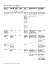
... factory. the NIC vendor. protection method varies by the HP Sure Start BIOS code, EC Embedded Controller. this memory? Nonvolatile memory usage Nonvolatile Memory Type Amount (Size) HP Sure Start flash 2 MBytes (select models only) Does this memory when information. critical System solely by memory vendor. The specific write- render the PC non- settings are input using a utility from firmware. No Real Time Clock 256 Bytes No (RTC) battery backed-up CMOS This memory...
... factory. the NIC vendor. protection method varies by the HP Sure Start BIOS code, EC Embedded Controller. this memory? Nonvolatile memory usage Nonvolatile Memory Type Amount (Size) HP Sure Start flash 2 MBytes (select models only) Does this memory when information. critical System solely by memory vendor. The specific write- render the PC non- settings are input using a utility from firmware. No Real Time Clock 256 Bytes No (RTC) battery backed-up CMOS This memory...
Maintenance and Service Guide
Page 95
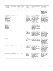
... using Only firmware updates the Management Engine digitally signed by user application can be entered at the factory. not made public. Nonvolatile memory usage 85 Nonvolatile Memory Type Amount (Size) Does this area. whenever the flash requires an upgrade. from Windows. memory are not made available to the public unless a firmware upgrade is the purpose of the driver from the silicon vendor. Downloads, and then follow the on -screen instructions...
... using Only firmware updates the Management Engine digitally signed by user application can be entered at the factory. not made public. Nonvolatile memory usage 85 Nonvolatile Memory Type Amount (Size) Does this area. whenever the flash requires an upgrade. from Windows. memory are not made available to the public unless a firmware upgrade is the purpose of the driver from the silicon vendor. Downloads, and then follow the on -screen instructions...

Maintenance and Service Guide
Page 96
... Secure Boot keys. Turn on or restart the computer, and then press esc while the "Press the ESC key for the older BIOS architecture, but supports much of your hard drive. Select Main, and then select Restore defaults. Select Main, select Save Changes and Exit, and then follow the on -screen instructions. How can use either a pointing device (Touchscreen, TouchPad, pointing stick, or USB mouse) or the keyboard to factory defaults...
... Secure Boot keys. Turn on or restart the computer, and then press esc while the "Press the ESC key for the older BIOS architecture, but supports much of your hard drive. Select Main, and then select Restore defaults. Select Main, select Save Changes and Exit, and then follow the on -screen instructions. How can use either a pointing device (Touchscreen, TouchPad, pointing stick, or USB mouse) or the keyboard to factory defaults...
Maintenance and Service Guide
Page 97
... Secure Boot Keys, but make the selection to its previously safe state, without user intervention. c. Use the same Secure Boot access procedure you enabled Secure Boot and created Custom Secure Boot Keys, simply disabling Secure Boot will not clear the keys. Secure Boot is attacked, HP Sure Start restores the BIOS to clear or delete all Secure Boot Keys. a. Follow the on -screen instructions to ensure that continuously monitors your country. At the Secure Boot Configuration window, select Secure Boot, select Clear Secure Boot Keys...
... Secure Boot Keys, but make the selection to its previously safe state, without user intervention. c. Use the same Secure Boot access procedure you enabled Secure Boot and created Custom Secure Boot Keys, simply disabling Secure Boot will not clear the keys. Secure Boot is attacked, HP Sure Start restores the BIOS to clear or delete all Secure Boot Keys. a. Follow the on -screen instructions to ensure that continuously monitors your country. At the Secure Boot Configuration window, select Secure Boot, select Clear Secure Boot Keys...

Maintenance and Service Guide
Page 99
... TouchPad 10 computer major components 17 Computer Setup navigating and selecting 66 restoring factory settings 67 connectors docking 7, 14 power 7 D display components 9 display assembly removal 59 spare part numbers 59 subcomponents 22 display panel product description 1 removal 63 spare part numbers 22, 64 display panel cable removal 65 spare part number 23, 65 display panel cable, illustrated 24 DisplayPort-to-HDMI 1.4 adapter, spare part number 26 docking connector 7, 14 docking station, spare part number 26 docking station, spare part numbers 26 drive light 15 Dual-Mode...
... TouchPad 10 computer major components 17 Computer Setup navigating and selecting 66 restoring factory settings 67 connectors docking 7, 14 power 7 D display components 9 display assembly removal 59 spare part numbers 59 subcomponents 22 display panel product description 1 removal 63 spare part numbers 22, 64 display panel cable removal 65 spare part number 23, 65 display panel cable, illustrated 24 DisplayPort-to-HDMI 1.4 adapter, spare part number 26 docking connector 7, 14 docking station, spare part number 26 docking station, spare part numbers 26 drive light 15 Dual-Mode...
Maintenance and Service Guide
Page 100
...23 pointing device, product description 3 pointing stick 10 pointing stick cable, illustrated 24 pointing stick covers, spare part number 27 ports Dual-Mode DisplayPort 6 external monitor 8 monitor 8 product description 3 USB 3.1 charging (powered) 8 USB Type-C (charging) 6 power button 12 power connector 7 power cord set requirements 80 spare part numbers 26, 27 power light 11, 15 power requirements, product description 3 processor product description 1 product description audio 2 chipset 1 display panel 1 Ethernet 2 external media cards 3 graphics 1 hard drive 1, 2 keyboard 3 memory module 1
...23 pointing device, product description 3 pointing stick 10 pointing stick cable, illustrated 24 pointing stick covers, spare part number 27 ports Dual-Mode DisplayPort 6 external monitor 8 monitor 8 product description 3 USB 3.1 charging (powered) 8 USB Type-C (charging) 6 power button 12 power connector 7 power cord set requirements 80 spare part numbers 26, 27 power light 11, 15 power requirements, product description 3 processor product description 1 product description audio 2 chipset 1 display panel 1 Ethernet 2 external media cards 3 graphics 1 hard drive 1, 2 keyboard 3 memory module 1

Maintenance and Service Guide
Page 101
... cover spare part number 19 TouchPad buttons 10 components 10 zone 10 TouchPad button board removal 56 spare part number 20, 56 TouchPad light 10 TouchPad on/off button 10 TPM settings 69 U USB 3.1 charging (powered) port 8 USB 3.1 port 6 USB legacy support 66 USB ports 6 USB Type-C (charging) port 6 V vents 8, 14 video, product description 2 volume mute light 11 W warranty period 16 webcam 9 webcam light 9 webcam module removal 62 spare part number 22, 63 webcam, location 9 Windows system restore point 73, 74 Windows key 13 Windows tools using 74 wireless antenna location 9 spare part number...
... cover spare part number 19 TouchPad buttons 10 components 10 zone 10 TouchPad button board removal 56 spare part number 20, 56 TouchPad light 10 TouchPad on/off button 10 TPM settings 69 U USB 3.1 charging (powered) port 8 USB 3.1 port 6 USB legacy support 66 USB ports 6 USB Type-C (charging) port 6 V vents 8, 14 video, product description 2 volume mute light 11 W warranty period 16 webcam 9 webcam light 9 webcam module removal 62 spare part number 22, 63 webcam, location 9 Windows system restore point 73, 74 Windows key 13 Windows tools using 74 wireless antenna location 9 spare part number...


