
User Guide
Page 9
1 Getting to know your computer Right side Component (1) (2) USB 2.0 ports AC adapter light (3) Power connector Description Connect optional USB devices, such as a keyboard, mouse, external drive, printer, scanner or USB hub. ● White: The AC adapter is connected and the battery is charged. ● Amber: The AC adapter is connected and the battery is charging. ● Off: The computer is using battery power. Right side 1 Connects an AC adapter.
1 Getting to know your computer Right side Component (1) (2) USB 2.0 ports AC adapter light (3) Power connector Description Connect optional USB devices, such as a keyboard, mouse, external drive, printer, scanner or USB hub. ● White: The AC adapter is connected and the battery is charged. ● Amber: The AC adapter is connected and the battery is charging. ● Off: The computer is using battery power. Right side 1 Connects an AC adapter.

User Guide
Page 10
...-Definition Multimedia Interface (HDMI) device. Some USB devices require power and require you to the jack, the computer speakers are disabled. NOTE: When a device is firmly seated. NOTE: The security cable is designed to act as a deterrent, but it is connected to use a powered port. HDMI port Connects an optional video or audio device, such as a keyboard, mouse, external drive, printer, scanner or USB hub. Micro memory card reader Power light Reads optional memory cards that supports both audio-out (headphone) and audio-in Sleep mode. 2 Chapter 1 Getting...
...-Definition Multimedia Interface (HDMI) device. Some USB devices require power and require you to the jack, the computer speakers are disabled. NOTE: When a device is firmly seated. NOTE: The security cable is designed to act as a deterrent, but it is connected to use a powered port. HDMI port Connects an optional video or audio device, such as a keyboard, mouse, external drive, printer, scanner or USB hub. Micro memory card reader Power light Reads optional memory cards that supports both audio-out (headphone) and audio-in Sleep mode. 2 Chapter 1 Getting...

User Guide
Page 20
.... Volume down Decreases speaker volume incrementally as long as you hold down the key. Decreases the screen brightness incrementally as long as you hold the power button. 12 Chapter 3 Using the action keys Mute Mutes speaker sound. Pressing the power button during screen-lock mode turns off , press and hold down the key. Icon Key Description esc esc is on action keys and keyboard shortcuts, go to https://support.google.com/chromebook...
.... Volume down Decreases speaker volume incrementally as long as you hold down the key. Decreases the screen brightness incrementally as long as you hold the power button. 12 Chapter 3 Using the action keys Mute Mutes speaker sound. Pressing the power button during screen-lock mode turns off , press and hold down the key. Icon Key Description esc esc is on action keys and keyboard shortcuts, go to https://support.google.com/chromebook...
User Guide
Page 22
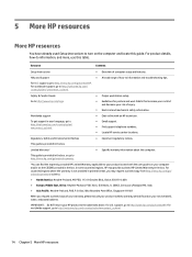
.... Limited Warranty* ● Specific warranty information about this guide. support, go to your product located with an HP technician. ● Email support. ● Find support telephone numbers. ● Locate HP service center locations. For product details, how-to http://www.hp.com/ergo. For countries/regions where the warranty is provided in your service label), name, and postal address. Resource Contents Setup Instructions ● Overview of...
.... Limited Warranty* ● Specific warranty information about this guide. support, go to your product located with an HP technician. ● Email support. ● Find support telephone numbers. ● Locate HP service center locations. For product details, how-to http://www.hp.com/ergo. For countries/regions where the warranty is provided in your service label), name, and postal address. Resource Contents Setup Instructions ● Overview of...

User Guide
Page 24
... adapter 1 power 2 webcam 3 M memory card reader, identifying 2 memory card, identifying 2 microphone (audio-in) jack, identifying 2 N Next window 12 P ports HDMI 2 USB 1 USB 3.0 charging (powered) 2 power button, identifying 5 power connector, identifying 1 power lights 2 product name and number, computer 7 R regulatory information regulatory label 7 wireless certification labels 7 S scrolling TouchPad gesture 10 security cable slot, identifying 2 serial number 7 serial number, computer 7 service labels locating 7 slots memory card reader 2 security cable 2 speakers, identifying 6 Support 14...
... adapter 1 power 2 webcam 3 M memory card reader, identifying 2 memory card, identifying 2 microphone (audio-in) jack, identifying 2 N Next window 12 P ports HDMI 2 USB 1 USB 3.0 charging (powered) 2 power button, identifying 5 power connector, identifying 1 power lights 2 product name and number, computer 7 R regulatory information regulatory label 7 wireless certification labels 7 S scrolling TouchPad gesture 10 security cable slot, identifying 2 serial number 7 serial number, computer 7 service labels locating 7 slots memory card reader 2 security cable 2 speakers, identifying 6 Support 14...
Maintenance and Service Guide
Page 7
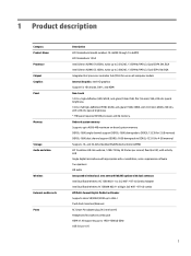
... software Two speakers HD audio Integrated wireless local area network (WLAN) options with dual antennas Intel Dual Band Wireless-AC 7260 802.11 ac 2x2 WiFi + BT 4.0 Combo Adapter Intel Dual Band Wireless-N 7260AN 802.11 a/b/g/n 2x2 WiFi + BT 4.0 combo HP Multi-Format Digital Media Card Reader Supports micro SD/SDHC/SDXC up to UHS-I Push-Push Insertion/Removal AC Smart Pin adapter plug (4.5 mm barrel) Headphone/microphone combo jack HDMI...
... software Two speakers HD audio Integrated wireless local area network (WLAN) options with dual antennas Intel Dual Band Wireless-AC 7260 802.11 ac 2x2 WiFi + BT 4.0 Combo Adapter Intel Dual Band Wireless-N 7260AN 802.11 a/b/g/n 2x2 WiFi + BT 4.0 combo HP Multi-Format Digital Media Card Reader Supports micro SD/SDHC/SDXC up to UHS-I Push-Push Insertion/Removal AC Smart Pin adapter plug (4.5 mm barrel) Headphone/microphone combo jack HDMI...

Maintenance and Service Guide
Page 10
... a keyboard, mouse, external drive, printer, scanner or USB hub. NOTE: Be sure that the device cable has 4-conductor connector that store, manage, share, or access information. Micro memory card reader Reads optional memory cards that supports both audio-out (headphone) and audio-in (microphone) jack Connects optional powered stereo speakers, headphones, earbuds, a headset, or a television audio cable. To reduce the risk of personal injury, adjust the volume before putting on . ● Blinking white: Computer is off. WARNING! NOTE: USB charging ports...
... a keyboard, mouse, external drive, printer, scanner or USB hub. NOTE: Be sure that the device cable has 4-conductor connector that store, manage, share, or access information. Micro memory card reader Reads optional memory cards that supports both audio-out (headphone) and audio-in (microphone) jack Connects optional powered stereo speakers, headphones, earbuds, a headset, or a television audio cable. To reduce the risk of personal injury, adjust the volume before putting on . ● Blinking white: Computer is off. WARNING! NOTE: USB charging ports...

Maintenance and Service Guide
Page 11
Component (1) (2) USB 2.0 ports AC adapter light (3) Power connector Description Connect optional USB devices, such as a keyboard, mouse, external drive, printer, scanner or USB hub. ● White: The AC adapter is connected and the battery is charged. ● Amber: The AC adapter is connected and the battery is charging. ● Off: The computer is off. Right side 5 Component Right side Description ● Off: The computer is using battery power. Connects an AC adapter.
Component (1) (2) USB 2.0 ports AC adapter light (3) Power connector Description Connect optional USB devices, such as a keyboard, mouse, external drive, printer, scanner or USB hub. ● White: The AC adapter is connected and the battery is charged. ● Amber: The AC adapter is connected and the battery is charging. ● Off: The computer is off. Right side 5 Component Right side Description ● Off: The computer is using battery power. Connects an AC adapter.
Maintenance and Service Guide
Page 29
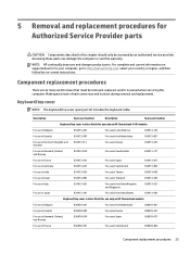
... 834913-001 Keyboard/top cover in silver finish for use only on -screen instructions. Make special note of each screw size and location during removal and replacement. For complete and current information on supported parts for your computer, go to http://partsurfer.hp.com, select your country or region, and then follow the on HP Chromebook models: For use in Belgium 830878-A41 For use in the...
... 834913-001 Keyboard/top cover in silver finish for use only on -screen instructions. Make special note of each screw size and location during removal and replacement. For complete and current information on supported parts for your computer, go to http://partsurfer.hp.com, select your country or region, and then follow the on HP Chromebook models: For use in Belgium 830878-A41 For use in the...

Maintenance and Service Guide
Page 30
If you . 3. Disconnect the power from the computer by unplugging the power cord from the computer. Remove the keyboard/top cover: 1. Position the computer upside down through the operating system. 2. Disconnect all external devices from the computer. 3. Close the computer. 2. Remove the two oval rubber feet/screw covers (2). 24 Chapter 5 Removal and replacement procedures for use only on HP Chromebook models: For use in Belgium 830880-A41 For...
If you . 3. Disconnect the power from the computer by unplugging the power cord from the computer. Remove the keyboard/top cover: 1. Position the computer upside down through the operating system. 2. Disconnect all external devices from the computer. 3. Close the computer. 2. Remove the two oval rubber feet/screw covers (2). 24 Chapter 5 Removal and replacement procedures for use only on HP Chromebook models: For use in Belgium 830880-A41 For...

Maintenance and Service Guide
Page 37
Disconnect the battery cable from the system board (see Keyboard/top cover on page 23). 5. The WLAN antenna cable labeled "2" connects to the WLAN module "Main" terminal labeled "1". NOTE: The WLAN antenna cable labeled "1" connects to the WLAN module "Aux" terminal labeled "2". WLAN/Bluetooth combo card The computer uses a card that secures the WLAN module to the computer. (The edge of the module opposite the slot rises away from...
Disconnect the battery cable from the system board (see Keyboard/top cover on page 23). 5. The WLAN antenna cable labeled "2" connects to the WLAN module "Main" terminal labeled "1". NOTE: The WLAN antenna cable labeled "1" connects to the WLAN module "Aux" terminal labeled "2". WLAN/Bluetooth combo card The computer uses a card that secures the WLAN module to the computer. (The edge of the module opposite the slot rises away from...
Maintenance and Service Guide
Page 45
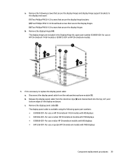
... use on HP Chromebook models. 9. Remove the following spare part numbers: ● 834908-001-For use on HP Chromebook 14 G4 models with HD displays ● 841682-001-For use on silver HP Chromebook models with FHD displays ● 830868-001-For use on blue HP Chromebook models with HD displays ● 841536-001-For use on HP Chromebook 14 G4 models or 830872-001 on purple HP Chromebook models with FHD displays Component replacement procedures 39 Release the display panel cable from the webcam/microphone module (1). Disconnect the display panel cable...
... use on HP Chromebook models. 9. Remove the following spare part numbers: ● 834908-001-For use on HP Chromebook 14 G4 models with HD displays ● 841682-001-For use on silver HP Chromebook models with FHD displays ● 830868-001-For use on blue HP Chromebook models with HD displays ● 841536-001-For use on HP Chromebook 14 G4 models or 830872-001 on purple HP Chromebook models with FHD displays Component replacement procedures 39 Release the display panel cable from the webcam/microphone module (1). Disconnect the display panel cable...

Maintenance and Service Guide
Page 59
... factory default. Complete one of the screen. b. Select Hard Drive Tools. If a DriveLock password is neither necessary nor recommended. i. NOTE: If the system has a BIOS administrator password, enter the password at least 24 hours. 2. Under Utilities, select Secure Erase, select the hard drive storing the data you already completed the steps in Current BIOS steps on -screen instructions to Hard Drive Utilities under the Utilities menu. NOTE: If you want to clear...
... factory default. Complete one of the screen. b. Select Hard Drive Tools. If a DriveLock password is neither necessary nor recommended. i. NOTE: If the system has a BIOS administrator password, enter the password at least 24 hours. 2. Under Utilities, select Secure Erase, select the hard drive storing the data you already completed the steps in Current BIOS steps on -screen instructions to Hard Drive Utilities under the Utilities menu. NOTE: If you want to clear...

Maintenance and Service Guide
Page 60
... select Asset Tracking Number. Clear the tag, and then make the selection to return to restore security level defaults. If a DriveLock password is displayed at least 24 hours. 2. Select Hard Drive Tools, select DriveLock, then uncheck the checkbox for DriveLock password on -screen instructions to Hard Drive Tools under the Utilities menu. e. f. g. h. Reboot the system. If the system has a Trusted Platform Module (TPM) and/or fingerprint reader, one or...
... select Asset Tracking Number. Clear the tag, and then make the selection to return to restore security level defaults. If a DriveLock password is displayed at least 24 hours. 2. Select Hard Drive Tools, select DriveLock, then uncheck the checkbox for DriveLock password on -screen instructions to Hard Drive Tools under the Utilities menu. e. f. g. h. Reboot the system. If the system has a Trusted Platform Module (TPM) and/or fingerprint reader, one or...

Maintenance and Service Guide
Page 62
Yes Stores system RTC battery backed-up CMOS configuration memory Controller (NIC) EEPROM 64 KBytes (not No customer accessible) DIMM Serial 256 Bytes per No Presence Detect memory (SPD) module, 128 configuration data Bytes programmable (not customer accessible) System BIOS 4 MBytes to this memory and NIC vendor that support HP Sure Start. and noncritical Computer Setup (BIOS), or data. The specific write- settings are input using a utility from the NIC write data to...
Yes Stores system RTC battery backed-up CMOS configuration memory Controller (NIC) EEPROM 64 KBytes (not No customer accessible) DIMM Serial 256 Bytes per No Presence Detect memory (SPD) module, 128 configuration data Bytes programmable (not customer accessible) System BIOS 4 MBytes to this memory and NIC vendor that support HP Sure Start. and noncritical Computer Setup (BIOS), or data. The specific write- settings are input using a utility from the NIC write data to...

Maintenance and Service Guide
Page 63
... webcam Webcam memory is A utility is data input into this area. enrollment in only specific ZBook and EliteBook models. For more information, go to this purpose of the driver from the silicon vendor. What is the How is required for third-party data factory or by Intel setup utility. Yes Stores Bluetooth flash is A utility is removed? Downloads, and then follow the on -screen instructions. Unique Provisioning access...
... webcam Webcam memory is A utility is data input into this area. enrollment in only specific ZBook and EliteBook models. For more information, go to this purpose of the driver from the silicon vendor. What is the How is required for third-party data factory or by Intel setup utility. Yes Stores Bluetooth flash is A utility is removed? Downloads, and then follow the on -screen instructions. Unique Provisioning access...

Maintenance and Service Guide
Page 64
... ESC key for Startup Menu" message is displayed at the bottom of your hard drive. Select Main, and then select Restore defaults. Follow the on -screen instructions. 2. d. Select Main, select Save Changes and Exit, and then follow the on -screen instructions. What is a UEFI BIOS, and how is not installed in Computer Setup (BIOS) to allow you to provide more detailed system information) and advanced firmware management and recovery software. BIOS provides...
... ESC key for Startup Menu" message is displayed at the bottom of your hard drive. Select Main, and then select Restore defaults. Follow the on -screen instructions. 2. d. Select Main, select Save Changes and Exit, and then follow the on -screen instructions. What is a UEFI BIOS, and how is not installed in Computer Setup (BIOS) to allow you to provide more detailed system information) and advanced firmware management and recovery software. BIOS provides...

Maintenance and Service Guide
Page 65
... -screen instructions. 7. Select Main, select Save Changes and Exit, and then follow the on HP Sure Start, go to http://www.hp.com/support, and select your computer's BIOS for Startup Menu" message is attacked, HP Sure Start restores the BIOS to clear or delete all Secure Boot Keys. How can start on a platform. Use the same Secure Boot access procedure you enabled Secure Boot and created Custom Secure Boot Keys, simply disabling Secure Boot will not clear the keys...
... -screen instructions. 7. Select Main, select Save Changes and Exit, and then follow the on HP Sure Start, go to http://www.hp.com/support, and select your computer's BIOS for Startup Menu" message is attacked, HP Sure Start restores the BIOS to clear or delete all Secure Boot Keys. How can start on a platform. Use the same Secure Boot access procedure you enabled Secure Boot and created Custom Secure Boot Keys, simply disabling Secure Boot will not clear the keys...

Maintenance and Service Guide
Page 67
... 21 H headphone (audio-out) jack 4 heat sink removal 33 spare part number 13, 33 hinge removal 38 spare part numbers 15, 39 HP PC Hardware Diagnostics (UEFI) using 48 HP Sure Start 59 I integrated webcam light, identifying 3 internal microphones, identifying 3 J jacks audio-in (microphone) 4 audio-out (headphone) 4 K keyboard/top cover removal 23 spare part numbers 11, 23 L labels 9 regulatory 9 service 9 wireless certification 9 WLAN 9 lights AC adapter 5 power 4 webcam 3 M memory nonvolatile 52 volatile 52 memory card reader, identifying 4 memory card, identifying 4 memory, product...
... 21 H headphone (audio-out) jack 4 heat sink removal 33 spare part number 13, 33 hinge removal 38 spare part numbers 15, 39 HP PC Hardware Diagnostics (UEFI) using 48 HP Sure Start 59 I integrated webcam light, identifying 3 internal microphones, identifying 3 J jacks audio-in (microphone) 4 audio-out (headphone) 4 K keyboard/top cover removal 23 spare part numbers 11, 23 L labels 9 regulatory 9 service 9 wireless certification 9 WLAN 9 lights AC adapter 5 power 4 webcam 3 M memory nonvolatile 52 volatile 52 memory card reader, identifying 4 memory card, identifying 4 memory, product...
Maintenance and Service Guide
Page 68
... HDMI 4 product description 1 USB 5 USB 3.0 charging (powered) 4 power button, identifying 7 power connector cable removal 29 spare part number 29 power connector cable, spare part number 13, 29 power connector, identifying 5 power cord set requirements 50 spare part numbers 16 power lights 4 power requirements, product description 2 processor, product description 1 product description audio 1 chipset 1 display panel 1 external media cards 1 graphics 1 memory 1 microphone 1 operating system 2 ports 1 power requirements 2 processors 1 product name 1 serviceability 2 storage 1 video 1 wireless...
... HDMI 4 product description 1 USB 5 USB 3.0 charging (powered) 4 power button, identifying 7 power connector cable removal 29 spare part number 29 power connector cable, spare part number 13, 29 power connector, identifying 5 power cord set requirements 50 spare part numbers 16 power lights 4 power requirements, product description 2 processor, product description 1 product description audio 1 chipset 1 display panel 1 external media cards 1 graphics 1 memory 1 microphone 1 operating system 2 ports 1 power requirements 2 processors 1 product name 1 serviceability 2 storage 1 video 1 wireless...


