
Maintenance and Service Guide
Page 5
...Bottom ...8 Labels ...9 3 Illustrated parts catalog ...10 Computer major components ...10 Display assembly subcomponents ...14 Rubber Kit ...16 Miscellaneous parts ...16 4 Removal and replacement preliminary requirements 18 Tools required ...18 Service considerations ...18 Plastic parts ...18 Cables and connectors ...19...damage ...19 Packaging and transporting guidelines 21 Workstation guidelines 21 5 Removal and replacement procedures for Authorized Service Provider parts 23 Component replacement procedures ...23 Keyboard/top cover ...23 TouchPad ...27 Power connector cable ...29 USB board ...
...Bottom ...8 Labels ...9 3 Illustrated parts catalog ...10 Computer major components ...10 Display assembly subcomponents ...14 Rubber Kit ...16 Miscellaneous parts ...16 4 Removal and replacement preliminary requirements 18 Tools required ...18 Service considerations ...18 Plastic parts ...18 Cables and connectors ...19...damage ...19 Packaging and transporting guidelines 21 Workstation guidelines 21 5 Removal and replacement procedures for Authorized Service Provider parts 23 Component replacement procedures ...23 Keyboard/top cover ...23 TouchPad ...27 Power connector cable ...29 USB board ...
Maintenance and Service Guide
Page 8
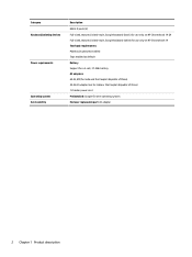
...-sized, textured, island-style, Google keyboard (black) for use only on HP Chromebook 14 G4 Full-sized, textured, island-style, Google keyboard (white) for use only on HP Chromebook 14 Touchpad requirements: Multitouch gestures enabled Taps ...enabled as default Battery Support for a 3-cell, 37-WHr battery AC adapters 65-W, EM (for India and the People's Republic of China) 45-W AC adapter (not for India or the People's Republic of China) 1.0 meter power cord Preinstalled: Google Chrome operating system End user replaceable...
...-sized, textured, island-style, Google keyboard (black) for use only on HP Chromebook 14 G4 Full-sized, textured, island-style, Google keyboard (white) for use only on HP Chromebook 14 Touchpad requirements: Multitouch gestures enabled Taps ...enabled as default Battery Support for a 3-cell, 37-WHr battery AC adapters 65-W, EM (for India and the People's Republic of China) 45-W AC adapter (not for India or the People's Republic of China) 1.0 meter power cord Preinstalled: Google Chrome operating system End user replaceable...
Maintenance and Service Guide
Page 29
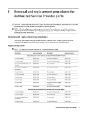
... service provider. NOTE: HP continually improves and changes product parts. Keyboard/top cover NOTE: The keyboard/top cover spare part kit includes the keyboard cable. Description Spare part number Description Spare part number Keyboard/top cover in silver finish for use only on HP Chromebook 14 G4 models: For use in...Norway 830878-DH1 For use in Spain 830878-071 For use in France 830878-051 For use in Switzerland 830878-BG1 Component replacement procedures 23 Accessing these parts can damage the computer or void the warranty. Make special note of each screw size and ...
... service provider. NOTE: HP continually improves and changes product parts. Keyboard/top cover NOTE: The keyboard/top cover spare part kit includes the keyboard cable. Description Spare part number Description Spare part number Keyboard/top cover in silver finish for use only on HP Chromebook 14 G4 models: For use in...Norway 830878-DH1 For use in Spain 830878-071 For use in France 830878-051 For use in Switzerland 830878-BG1 Component replacement procedures 23 Accessing these parts can damage the computer or void the warranty. Make special note of each screw size and ...

Maintenance and Service Guide
Page 30
... the operating system. 2. If you are removed from the defective keyboard/top cover and installed on the replacement keyboard/top cover. Remove the two oval rubber feet/screw covers (2). 24 Chapter 5 Removal and replacement procedures for use only on HP Chromebook models: For use in Belgium 830880-A41 For use in the...Kingdom and Singapore 830878-031 For use in Italy 830878-061 For use in the United States 830878-001 Keyboard/top cover in blue finish for use only on HP Chromebook models: For use in Belgium 830879-A41 For use in the Netherlands 830879-B31 For use in Canada...
... the operating system. 2. If you are removed from the defective keyboard/top cover and installed on the replacement keyboard/top cover. Remove the two oval rubber feet/screw covers (2). 24 Chapter 5 Removal and replacement procedures for use only on HP Chromebook models: For use in Belgium 830880-A41 For use in the...Kingdom and Singapore 830878-031 For use in Italy 830878-061 For use in the United States 830878-001 Keyboard/top cover in blue finish for use only on HP Chromebook models: For use in Belgium 830879-A41 For use in the Netherlands 830879-B31 For use in Canada...

Maintenance and Service Guide
Page 31
... included in the Rubber Kit, spare part number 834911-001 for use only on HP Chromebook 14 G4 models and 830875-001 for use only on HP Chromebook models. 6. Lift the tape (2) that secure the keyboard/top cover to the base enclosure. 7. Component replacement procedures 25 Remove the middle smaller rubber foot/screw cover (3). Open the computer as...
... included in the Rubber Kit, spare part number 834911-001 for use only on HP Chromebook 14 G4 models and 830875-001 for use only on HP Chromebook models. 6. Lift the tape (2) that secure the keyboard/top cover to the base enclosure. 7. Component replacement procedures 25 Remove the middle smaller rubber foot/screw cover (3). Open the computer as...

Maintenance and Service Guide
Page 32
11. Release the zero insertion force (ZIF) connector (3) to which the TouchPad cable is attached, and then disconnect the keyboard cable (4) from the system board. 13. Remove keyboard/top cover (7) by sliding it forward. Reverse this procedure to which the keyboard cable is attached, and then disconnect the TouchPad cable (6) from the system board. 12. Release the ZIF connector (5) to install the keyboard/top cover. 26 Chapter 5 Removal and replacement procedures for Authorized Service Provider parts
11. Release the zero insertion force (ZIF) connector (3) to which the TouchPad cable is attached, and then disconnect the keyboard cable (4) from the system board. 13. Remove keyboard/top cover (7) by sliding it forward. Reverse this procedure to which the keyboard cable is attached, and then disconnect the TouchPad cable (6) from the system board. 12. Release the ZIF connector (5) to install the keyboard/top cover. 26 Chapter 5 Removal and replacement procedures for Authorized Service Provider parts
Maintenance and Service Guide
Page 33
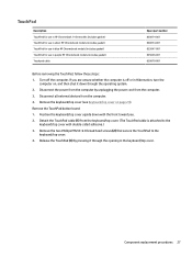
....) 3. Disconnect all external devices from the computer. 3. Detach the TouchPad cable (1) from the keyboard/top cover. (The TouchPad cable is off the computer. Component replacement procedures 27 If you . 2. Remove the two Phillips PM2.0×2.0 broad head screws (2) that...the keyboard/top cover. 4. Position the keyboard/top cover upside down through the opening in the keyboard/top cover. TouchPad Description TouchPad for use in HP Chromebook 14 G4 models (includes gasket) TouchPad for use in silver HP Chromebook models (includes gasket) TouchPad for use in blue HP Chromebook ...
....) 3. Disconnect all external devices from the computer. 3. Detach the TouchPad cable (1) from the keyboard/top cover. (The TouchPad cable is off the computer. Component replacement procedures 27 If you . 2. Remove the two Phillips PM2.0×2.0 broad head screws (2) that...the keyboard/top cover. 4. Position the keyboard/top cover upside down through the opening in the keyboard/top cover. TouchPad Description TouchPad for use in HP Chromebook 14 G4 models (includes gasket) TouchPad for use in silver HP Chromebook models (includes gasket) TouchPad for use in blue HP Chromebook ...

Maintenance and Service Guide
Page 35
Remove the keyboard/top cover (see Battery on page 42). Component replacement procedures 29 Disconnect the power from the computer by unplugging the power cord from the computer. 4. Disconnect all external devices from the computer. 3. ... base enclosure. 3. Remove the power connector cable (3). Reverse this procedure to install the power connector cable. Release the cable from the system board (see Keyboard/top cover on , and then shut it down through the operating system. 2. Remove the power connector cable: 1. Power connector cable Description Power connector cable...
Remove the keyboard/top cover (see Battery on page 42). Component replacement procedures 29 Disconnect the power from the computer by unplugging the power cord from the computer. 4. Disconnect all external devices from the computer. 3. ... base enclosure. 3. Remove the power connector cable (3). Reverse this procedure to install the power connector cable. Release the cable from the system board (see Keyboard/top cover on , and then shut it down through the operating system. 2. Remove the power connector cable: 1. Power connector cable Description Power connector cable...

Maintenance and Service Guide
Page 36
...screws (2) that secure the USB board to install the USB board. 30 Chapter 5 Removal and replacement procedures for Authorized Service Provider parts Disconnect all external devices from the system board (see Keyboard/top cover on , and then shut it down through the operating system. 2. Remove the... keyboard/top cover (see Battery on page 42). Disconnect the battery cable from the computer. 4. Release ...
...screws (2) that secure the USB board to install the USB board. 30 Chapter 5 Removal and replacement procedures for Authorized Service Provider parts Disconnect all external devices from the system board (see Keyboard/top cover on , and then shut it down through the operating system. 2. Remove the... keyboard/top cover (see Battery on page 42). Disconnect the battery cable from the computer. 4. Release ...

Maintenance and Service Guide
Page 37
...cable connects to the middle terminal on the WLAN module. 2. Disconnect the battery cable from the system board (see Keyboard/top cover on the WLAN module. Description Intel Dual Band Wireless-AC 7260 802.11 ac 2x2 WiFi + BT ... terminals on page 23). 5. Remove the Phillips PM2.0×4.0 screw (2) that provides both WLAN and Bluetooth functionality. Remove the keyboard/top cover (see Battery on , and then shut it down through the operating system. 2. NOTE: The WLAN antenna cable... edge of the module opposite the slot rises away from the computer.) Component replacement procedures 31
...cable connects to the middle terminal on the WLAN module. 2. Disconnect the battery cable from the system board (see Keyboard/top cover on the WLAN module. Description Intel Dual Band Wireless-AC 7260 802.11 ac 2x2 WiFi + BT ... terminals on page 23). 5. Remove the Phillips PM2.0×4.0 screw (2) that provides both WLAN and Bluetooth functionality. Remove the keyboard/top cover (see Battery on , and then shut it down through the operating system. 2. NOTE: The WLAN antenna cable... edge of the module opposite the slot rises away from the computer.) Component replacement procedures 31

Maintenance and Service Guide
Page 39
... shut it down through the operating system. 2. Remove the heat sink: 1. Disconnect the battery cable from the system board (see Keyboard/top cover on page 42). Component replacement procedures 33 Remove the keyboard/top cover (see Battery on page 23). 5. If you are unsure whether the computer is off the computer. Heat sink...
... shut it down through the operating system. 2. Remove the heat sink: 1. Disconnect the battery cable from the system board (see Keyboard/top cover on page 42). Component replacement procedures 33 Remove the keyboard/top cover (see Battery on page 23). 5. If you are unsure whether the computer is off the computer. Heat sink...

Maintenance and Service Guide
Page 41
...broad head screws (2) that secure the display assembly to the display panel assembly. Disconnect the battery cable from the system board (see Keyboard/top cover on , and then shut it is off the computer. If it down through the operating system. 2. Disconnect the wireless ...Disconnect all external devices from the system board. 2. Remove the display assembly: 1. b. The black WLAN antenna cable labeled "2/Aux" connects to replace the display enclosure or any of the display assembly subcomponents: a. Remove the two display bezel screw covers (1). Turn off or in Hibernation, turn...
...broad head screws (2) that secure the display assembly to the display panel assembly. Disconnect the battery cable from the system board (see Keyboard/top cover on , and then shut it is off the computer. If it down through the operating system. 2. Disconnect the wireless ...Disconnect all external devices from the system board. 2. Remove the display assembly: 1. b. The black WLAN antenna cable labeled "2/Aux" connects to replace the display enclosure or any of the display assembly subcomponents: a. Remove the two display bezel screw covers (1). Turn off or in Hibernation, turn...

Maintenance and Service Guide
Page 48
....0×3.0 screws (1) that secure the battery to the base enclosure. 42 Chapter 5 Removal and replacement procedures for Authorized Service Provider parts If you are unsure whether the computer is off the computer. Remove the keyboard/top cover (see Keyboard/top cover on , and then shut it down through the operating system. 2. Turn off...
....0×3.0 screws (1) that secure the battery to the base enclosure. 42 Chapter 5 Removal and replacement procedures for Authorized Service Provider parts If you are unsure whether the computer is off the computer. Remove the keyboard/top cover (see Keyboard/top cover on , and then shut it down through the operating system. 2. Turn off...

Maintenance and Service Guide
Page 50
... (2). 3. If you are unsure whether the computer is off the computer. Remove the keyboard/top cover (see Battery on page 42). Disconnect the power from the computer by using a tool to install the speakers. 44 Chapter 5 Removal and replacement procedures for Authorized Service Provider parts Reverse this procedure to pry up near...
... (2). 3. If you are unsure whether the computer is off the computer. Remove the keyboard/top cover (see Battery on page 42). Disconnect the power from the computer by using a tool to install the speakers. 44 Chapter 5 Removal and replacement procedures for Authorized Service Provider parts Reverse this procedure to pry up near...
Maintenance and Service Guide
Page 51
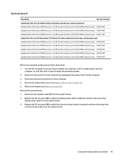
Turn off or in HP Chromebook 14 G4 models (includes alcohol pad, thermal tape, and thermal grease): Equipped with ... and then disconnect the display panel cable from the system board. 3. Remove the system board: 1. Component replacement procedures 45 System board Description Spare part number System board for use in Hibernation, turn the computer on, and...the computer is attached, and then disconnect the connector board cable from the computer. 4. Remove the battery (see Keyboard/top cover on page 23). 5. Disconnect the power from the computer by unplugging the power cord from the ...
Turn off or in HP Chromebook 14 G4 models (includes alcohol pad, thermal tape, and thermal grease): Equipped with ... and then disconnect the display panel cable from the system board. 3. Remove the system board: 1. Component replacement procedures 45 System board Description Spare part number System board for use in Hibernation, turn the computer on, and...the computer is attached, and then disconnect the connector board cable from the computer. 4. Remove the battery (see Keyboard/top cover on page 23). 5. Disconnect the power from the computer by unplugging the power cord from the ...

Maintenance and Service Guide
Page 54
... must use the keyboard attached. Go to stop a diagnostic test, press esc. Click Drivers & Downloads. 48 Chapter 7 Using HP PC Hardware Diagnostics (UEFI) Hard drive c. The HP PC Diagnostics home page is displayed. 2. 7 Using HP PC Hardware Diagnostics (UEFI) HP PC Hardware Diagnostics ... hardware replacement, a 24-digit Failure ID code is functioning properly. When HP PC Hardware Diagnostics (UEFI) detects a failure that are offered. There are provided in the following order: a. Downloading HP PC Hardware Diagnostics (UEFI) to a USB device NOTE: The HP PC ...
... must use the keyboard attached. Go to stop a diagnostic test, press esc. Click Drivers & Downloads. 48 Chapter 7 Using HP PC Hardware Diagnostics (UEFI) Hard drive c. The HP PC Diagnostics home page is displayed. 2. 7 Using HP PC Hardware Diagnostics (UEFI) HP PC Hardware Diagnostics ... hardware replacement, a 24-digit Failure ID code is functioning properly. When HP PC Hardware Diagnostics (UEFI) detects a failure that are offered. There are provided in the following order: a. Downloading HP PC Hardware Diagnostics (UEFI) to a USB device NOTE: The HP PC ...

Maintenance and Service Guide
Page 64
...advanced hardware diagnostics (with the ability to the EEPROM when the memory module is a replacement for steps to change the configuration of the legacy BIOS functionality. The DIMM SPD ...How can use either a pointing device (Touchscreen, TouchPad, pointing stick, or USB mouse) or the keyboard to factory settings)? See question and answer 7 for Startup Menu" message is required to write to...be written to run -time environment allows the loading and execution of the legacy BIOS. HP has provided options in Intel-based system boards"? Questions and answers 1. This information is...
...advanced hardware diagnostics (with the ability to the EEPROM when the memory module is a replacement for steps to change the configuration of the legacy BIOS functionality. The DIMM SPD ...How can use either a pointing device (Touchscreen, TouchPad, pointing stick, or USB mouse) or the keyboard to factory settings)? See question and answer 7 for Startup Menu" message is required to write to...be written to run -time environment allows the loading and execution of the legacy BIOS. HP has provided options in Intel-based system boards"? Questions and answers 1. This information is...


