
Service Manual
Page 8
... Contents Removal and Installation 8-1 Introduction 8-2 Safety Precautions 8-2 Electrostatic Discharge (ESD) Precautions 8-3 Required Tools 8-3 Screw Types 8-4 Left Hand Cover 8-5 Right Hand Cover 8-7 Front Panel 8-9 Window and Top Cover 8-10 Media Deflectors 8-11 Left End Roll-Feed 8-13 Right End Roll-Feed 8-15 Back Platen 8-17 Media Sensor 8-19 Formatter 8-20 LAN Card 8-21... Service Station Holder 8-57 Interconnect Cable 8-59 Ink Supply Tubes 8-60 Vacuum Fan 8-64 Pinch-Arm 8-66 Pinch-Arm Mechanism 8-67 Pinch-Arm Lever 8-69 6 HP DesignJets 500 and 800 Series Printers Service Manual
... Contents Removal and Installation 8-1 Introduction 8-2 Safety Precautions 8-2 Electrostatic Discharge (ESD) Precautions 8-3 Required Tools 8-3 Screw Types 8-4 Left Hand Cover 8-5 Right Hand Cover 8-7 Front Panel 8-9 Window and Top Cover 8-10 Media Deflectors 8-11 Left End Roll-Feed 8-13 Right End Roll-Feed 8-15 Back Platen 8-17 Media Sensor 8-19 Formatter 8-20 LAN Card 8-21... Service Station Holder 8-57 Interconnect Cable 8-59 Ink Supply Tubes 8-60 Vacuum Fan 8-64 Pinch-Arm 8-66 Pinch-Arm Mechanism 8-67 Pinch-Arm Lever 8-69 6 HP DesignJets 500 and 800 Series Printers Service Manual

Service Manual
Page 167
Removal and Installation 8 Screw Types 8-4 Left Hand Cover 8-5 Right Hand Cover 8-7 Front Panel 8-9 Window and Top Cover 8-10 Media Deflectors 8-11 Left End Roll-Feed 8-13 Right End Roll-Feed 8-15 Back Platen 8-17 Media Sensor 8-19 Formatter 8-20 LAN Card 8-21 Spittoon 8-... Fork Idler, Tensioner and Idler Pulley 8-74 Encoder Strip 8-76 Carriage Assembly (Including Belt) 8-78 Paper-Axis Motor 8-84 Drive Roller 8-86 Gear Assemblies 8-92 HP DesignJets 500 and 800 Series Printers Service Manual 8-1
Removal and Installation 8 Screw Types 8-4 Left Hand Cover 8-5 Right Hand Cover 8-7 Front Panel 8-9 Window and Top Cover 8-10 Media Deflectors 8-11 Left End Roll-Feed 8-13 Right End Roll-Feed 8-15 Back Platen 8-17 Media Sensor 8-19 Formatter 8-20 LAN Card 8-21 Spittoon 8-... Fork Idler, Tensioner and Idler Pulley 8-74 Encoder Strip 8-76 Carriage Assembly (Including Belt) 8-78 Paper-Axis Motor 8-84 Drive Roller 8-86 Gear Assemblies 8-92 HP DesignJets 500 and 800 Series Printers Service Manual 8-1
Service Manual
Page 176
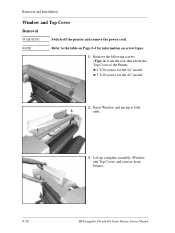
Remove the following screws (Type A) from Printer. 8-10 HP DesignJets 500 and 800 Series Printers Service Manual n 3 T-20 screws for the 24" model. Raise Window and unclip at both ends. 3. Removal and Installation Window and Top Cover Removal WARNING Switch off the printer and remove the power cord. NOTE Refer to the Printer: n 2 T-20 screws for the 42" model. 2. Lift up complete assembly (Window and Top Cover) and remove from the rear that attach the Top Cover to the table on Page 8-4 for information on screw types. 1.
Remove the following screws (Type A) from Printer. 8-10 HP DesignJets 500 and 800 Series Printers Service Manual n 3 T-20 screws for the 24" model. Raise Window and unclip at both ends. 3. Removal and Installation Window and Top Cover Removal WARNING Switch off the printer and remove the power cord. NOTE Refer to the Printer: n 2 T-20 screws for the 42" model. 2. Lift up complete assembly (Window and Top Cover) and remove from the rear that attach the Top Cover to the table on Page 8-4 for information on screw types. 1.
Service Manual
Page 206
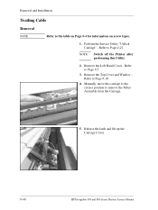
Remove the Left Hand Cover - Release the latch and lift up the Carriage Cover. 8-40 HP DesignJets 500 and 800 Series Printers Service Manual Refer to remove the Tubes Assembly from the Carriage. 5. Manually move the carriage to the correct position to Page 8-5. 3. Perform the Service Utility "Unlock Carriage" - NOTE Switch off the Printer after performing this Utility. 2. Remove the Top Cover and Window Refer to Page 4-22. Refer to Page 8-10. 4. Removal and Installation Trailing Cable Removal NOTE Refer to the table on Page 8-4 for information on screw types. 1.
Remove the Left Hand Cover - Release the latch and lift up the Carriage Cover. 8-40 HP DesignJets 500 and 800 Series Printers Service Manual Refer to remove the Tubes Assembly from the Carriage. 5. Manually move the carriage to the correct position to Page 8-5. 3. Perform the Service Utility "Unlock Carriage" - NOTE Switch off the Printer after performing this Utility. 2. Remove the Top Cover and Window Refer to Page 4-22. Refer to Page 8-10. 4. Removal and Installation Trailing Cable Removal NOTE Refer to the table on Page 8-4 for information on screw types. 1.

Service Manual
Page 228
Removal and Installation 8. Loosen 1 T-8 screw that secures the Tubes to Page 8-10. 9. Remove the Top Cover and Window Refer to the Carriage. Unclip 10. Unclip the Tubes from the Carriage and lift up. 8-62 HP DesignJets 500 and 800 Series Printers Service Manual
Removal and Installation 8. Loosen 1 T-8 screw that secures the Tubes to Page 8-10. 9. Remove the Top Cover and Window Refer to the Carriage. Unclip 10. Unclip the Tubes from the Carriage and lift up. 8-62 HP DesignJets 500 and 800 Series Printers Service Manual

Service Manual
Page 244
... Belt) Removal 1. NOTE Switch off the Printer after performing this Utility. 2. Remove the Top Cover and Window Refer to remove the Tubes Assembly from the Carriage. 8-78 HP DesignJets 500 and 800 Series Printers Service Manual Manually move the carriage to the correct position to Page... 8-10. 5. Remove the Service Station Holder Refer to Page 8-52. 7. Remove the Left Hand Cover - Refer to Page 8-57. 10. Refer to Page 8-76....
... Belt) Removal 1. NOTE Switch off the Printer after performing this Utility. 2. Remove the Top Cover and Window Refer to remove the Tubes Assembly from the Carriage. 8-78 HP DesignJets 500 and 800 Series Printers Service Manual Manually move the carriage to the correct position to Page... 8-10. 5. Remove the Service Station Holder Refer to Page 8-52. 7. Remove the Left Hand Cover - Refer to Page 8-57. 10. Refer to Page 8-76....
Service Manual
Page 252
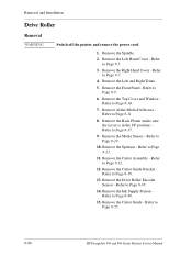
Remove the Right Hand Cover - Refer to Page 8-10. 7. Remove the Top Cover and Window Refer to Page 8-7. 4. Remove the Media Sensor - Remove the Cutter Assembly - Refer to Page 8-5. 3. Refer to Page 8-32. 12. Remove the Front Panel - Remove all ... to Page 8-11. 8. Refer to Page 8-55. 8-86 HP DesignJets 500 and 800 Series Printers Service Manual Remove the Drive Roller Encoder Sensor - Refer to Page 8-9. 6. Remove the Spindle. 2. Refer to Page 8-48. 15. Remove the Ink Supply Station Refer to Page 8-19. 10. Remove the Left and Right Trims. 5. Refer to...
Remove the Right Hand Cover - Refer to Page 8-10. 7. Remove the Top Cover and Window Refer to Page 8-7. 4. Remove the Media Sensor - Remove the Cutter Assembly - Refer to Page 8-5. 3. Refer to Page 8-32. 12. Remove the Front Panel - Remove all ... to Page 8-11. 8. Refer to Page 8-55. 8-86 HP DesignJets 500 and 800 Series Printers Service Manual Remove the Drive Roller Encoder Sensor - Refer to Page 8-9. 6. Remove the Spindle. 2. Refer to Page 8-48. 15. Remove the Ink Supply Station Refer to Page 8-19. 10. Remove the Left and Right Trims. 5. Refer to...

Service Manual
Page 258
Refer to Page 8-19. 10. Refer to Page 8-9. 6. Remove the Cutter Guide Bracket Refer to Page 8-48. 15. Remove the Ink Supply Station Refer to Page 8-36. 13. Remove the ... 8-38. 14. Remove the Drive Roller Encoder Sensor - Remove the Top Cover and Window Refer to Page 8-23. 11. Refer to Page 8-10. 7. Refer to Page 8-7. 4. Remove the Spindle. 2. Remove the Left Hand Cover - Refer to Page 8-84. 8-92 HP DesignJets 500 and 800 Series Printers Service Manual Remove the Cutter Guide - Removal...
Refer to Page 8-19. 10. Refer to Page 8-9. 6. Remove the Cutter Guide Bracket Refer to Page 8-48. 15. Remove the Ink Supply Station Refer to Page 8-36. 13. Remove the ... 8-38. 14. Remove the Drive Roller Encoder Sensor - Remove the Top Cover and Window Refer to Page 8-23. 11. Refer to Page 8-10. 7. Refer to Page 8-7. 4. Remove the Spindle. 2. Remove the Left Hand Cover - Refer to Page 8-84. 8-92 HP DesignJets 500 and 800 Series Printers Service Manual Remove the Cutter Guide - Removal...
Service Manual
Page 266
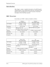
... MB 6 Gbytes (Asian Fonts included) Standard Standard 10-2 HP DesignJets 500 and 800 Series Printers Service Manual C7769B 42" Model - C7779C 42" Model - SKU Overview In total there are 8 SKU's which are detailed as follows: Part Number Resolution Languages Memory Hard Disk Network Card Formatter Windows HP DesignJet 500 24" Model - Mechanical and Printed Circuit...
... MB 6 Gbytes (Asian Fonts included) Standard Standard 10-2 HP DesignJets 500 and 800 Series Printers Service Manual C7769B 42" Model - C7779C 42" Model - SKU Overview In total there are 8 SKU's which are detailed as follows: Part Number Resolution Languages Memory Hard Disk Network Card Formatter Windows HP DesignJet 500 24" Model - Mechanical and Printed Circuit...
Service Manual
Page 282
...8-52 Solving Print Quality Problems 1-3 Spittoon 8-23 Spittoon 8-23 Trailing Cable 8-40 System Error Codes Vacuum Fan 8-64 0110 2-7 Window and Top Cover 8-10 0111 2-7 Required Tools 8-3 0112 2-7 Right End Roll-Feed 8-15 0113 2-8 Right Hand Cover 8-7 0210 2-8 0213 2-8 0310...Maintenance 9-4 0510 Warning 2-9 Scan-Axis Motor Assembly 8-29 0511 2-10 Scheduled Maintenance 9-3 0811 2-10 Index-4 HP DesignJets 500 and 800 Series Printers Service Manual Index Drive Roller Encoder Sensor 8-38 Scratching 6-10 Electronics Module 8-24 Screw Types 8-4 Encoder Strip 8-76 Service ...
...8-52 Solving Print Quality Problems 1-3 Spittoon 8-23 Spittoon 8-23 Trailing Cable 8-40 System Error Codes Vacuum Fan 8-64 0110 2-7 Window and Top Cover 8-10 0111 2-7 Required Tools 8-3 0112 2-7 Right End Roll-Feed 8-15 0113 2-8 Right Hand Cover 8-7 0210 2-8 0213 2-8 0310...Maintenance 9-4 0510 Warning 2-9 Scan-Axis Motor Assembly 8-29 0511 2-10 Scheduled Maintenance 9-3 0811 2-10 Index-4 HP DesignJets 500 and 800 Series Printers Service Manual Index Drive Roller Encoder Sensor 8-38 Scratching 6-10 Electronics Module 8-24 Screw Types 8-4 Encoder Strip 8-76 Service ...

Service Manual
Page 283
...Flowchart 6-7 How to use it 6-4 No Defects Found 6-8 Tubes Assembly 10-9 Turn Drive Roller 4-21 U Unlock Carriage 4-22 V Vacuum Fan 8-64 Vertical Line Straightness Problems 5-5 W Window and Top Cover 8-10 T Trailing Cable 8-40 Troubleshooting Boot-Up Sequence 1-12 Color differences 1-6 ...Formatter/Accessory Card LEDs 1-14 Media Jams 1-4 Paper-Axis Shutdowns 1-4 Power Switch LED 1-10 Priming Procedure 1-7 HP DesignJets 500 and 800 Series Printers...
...Flowchart 6-7 How to use it 6-4 No Defects Found 6-8 Tubes Assembly 10-9 Turn Drive Roller 4-21 U Unlock Carriage 4-22 V Vacuum Fan 8-64 Vertical Line Straightness Problems 5-5 W Window and Top Cover 8-10 T Trailing Cable 8-40 Troubleshooting Boot-Up Sequence 1-12 Color differences 1-6 ...Formatter/Accessory Card LEDs 1-14 Media Jams 1-4 Paper-Axis Shutdowns 1-4 Power Switch LED 1-10 Priming Procedure 1-7 HP DesignJets 500 and 800 Series Printers...

