
EcoStar Manual
Page 21
No bathers in Quick Clean mode. Input Voltage Within Range Motor Current 1.1A (0-13.0A) Power Usage 225W (0-2650W) Driver: 78C Heatsink: 67C Comm Bus Online (Addr: 1) Event log Press + to resume normal operation. SVRS inactive in water During Quick Clean press STOP/RESUME again to view Pump is stopped;
No bathers in Quick Clean mode. Input Voltage Within Range Motor Current 1.1A (0-13.0A) Power Usage 225W (0-2650W) Driver: 78C Heatsink: 67C Comm Bus Online (Addr: 1) Event log Press + to resume normal operation. SVRS inactive in water During Quick Clean press STOP/RESUME again to view Pump is stopped;

Technical Guide
Page 3
... property damage. Also, contact a licensed electrician for information on local electrical codes for electrocution and could result in the owner's manual and on drive or motor, turn off power supply to the drive. Failure to bond drive to electric supply. Hazardous voltage can cause severe injury and/or death. ...
... property damage. Also, contact a licensed electrician for information on local electrical codes for electrocution and could result in the owner's manual and on drive or motor, turn off power supply to the drive. Failure to bond drive to electric supply. Hazardous voltage can cause severe injury and/or death. ...
Technical Guide
Page 6
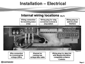
Electrical Internal wiring locations (fig 5) Wiring connection for incoming motor wires Wiring plug for relay connected controls & stop switch Wiring plug for wall mounted interface Wire connection for incoming line voltage (230v) Channel for running low voltage data cable Wiring plug for data link with Hayward/Goldline compatible software Controls Figure 5 Page 4 Installation -
Electrical Internal wiring locations (fig 5) Wiring connection for incoming motor wires Wiring plug for relay connected controls & stop switch Wiring plug for wall mounted interface Wire connection for incoming line voltage (230v) Channel for running low voltage data cable Wiring plug for data link with Hayward/Goldline compatible software Controls Figure 5 Page 4 Installation -
Technical Guide
Page 10
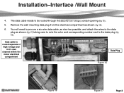
Data cable is routed separate of high voltage and in it's own channel within the motor electrical compartment Data Plug Figure 15 Figure 16 Figure 17 Page 8 Installation-Interface /Wall Mount 4. You will need to procure a six wire data cable, as ...
Data cable is routed separate of high voltage and in it's own channel within the motor electrical compartment Data Plug Figure 15 Figure 16 Figure 17 Page 8 Installation-Interface /Wall Mount 4. You will need to procure a six wire data cable, as ...

Technical Guide
Page 13
Cable used for data connections should be brought into the "line in" contacts on the Filter Pump Relay from a breaker in motor compartment. Filter Pump Replay AUX Relay AUX Relay AUX Relay Fig 24 Page 11 Pump power (230 VAC) needs to be rated for the pump (fig 24). Installation-Relay Connected Controls (Non Hayward/Goldline compatible software & third party controls) 1. The "Load Out" side will feed the incoming high voltage for maximum voltage in the control box.
Cable used for data connections should be brought into the "line in" contacts on the Filter Pump Relay from a breaker in motor compartment. Filter Pump Replay AUX Relay AUX Relay AUX Relay Fig 24 Page 11 Pump power (230 VAC) needs to be rated for the pump (fig 24). Installation-Relay Connected Controls (Non Hayward/Goldline compatible software & third party controls) 1. The "Load Out" side will feed the incoming high voltage for maximum voltage in the control box.
Technical Guide
Page 35
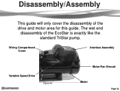
Wiring Compartment Cover Interface Assembly Variable Speed Drive Figure 63 Motor/Fan Shroud Motor Page 33 The wet end disassembly of the drive and motor area for this guide. Disassembly/Assembly This guide will only cover the disassembly of the EcoStar is exactly like the standard TriStar pump.
Wiring Compartment Cover Interface Assembly Variable Speed Drive Figure 63 Motor/Fan Shroud Motor Page 33 The wet end disassembly of the drive and motor area for this guide. Disassembly/Assembly This guide will only cover the disassembly of the EcoStar is exactly like the standard TriStar pump.
Technical Guide
Page 37
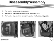
Remove the two screw as shown (fig 68) and place the interface assembly aside. Figure 66 Figure 67 Figure 68 Page 35 Disassembly/Assembly 3. Remove the interface assembly from the Motor drive (fig 67). 5. Remove the plug as shown (fig 66). 4.
Remove the two screw as shown (fig 68) and place the interface assembly aside. Figure 66 Figure 67 Figure 68 Page 35 Disassembly/Assembly 3. Remove the interface assembly from the Motor drive (fig 67). 5. Remove the plug as shown (fig 66). 4.

Technical Guide
Page 38
Remove the four hex head screws (two on each spade when reassembling (fig 71 & 72). Figure 69 Figure 70 Figure 71 Figure 72 Page 36 Note the color designation for each side) using a ¼" socket as shown (fig 69 & 70). Pull the three wire connectors off the spade terminals as the ground between the drive and the motor. 7. Disassembly/Assembly 6. Make sure during reassembly to tighten these screws fully as they act as shown.
Remove the four hex head screws (two on each spade when reassembling (fig 71 & 72). Figure 69 Figure 70 Figure 71 Figure 72 Page 36 Note the color designation for each side) using a ¼" socket as shown (fig 69 & 70). Pull the three wire connectors off the spade terminals as the ground between the drive and the motor. 7. Disassembly/Assembly 6. Make sure during reassembly to tighten these screws fully as they act as shown.

Technical Guide
Page 39
... disassembled. Disassembly/Assembly 8. During reassembly make sure all three wires through the hole provided to prevent pinching between the motor and the drive. 10. Lift the drive assembly partially off the motor and carefully pull each of the drive is removed before reassembly. Heatsink Figure 73 Figure 74 Page 37 Do not...
... disassembled. Disassembly/Assembly 8. During reassembly make sure all three wires through the hole provided to prevent pinching between the motor and the drive. 10. Lift the drive assembly partially off the motor and carefully pull each of the drive is removed before reassembly. Heatsink Figure 73 Figure 74 Page 37 Do not...

Technical Guide
Page 40
Remove the two screws on the top section of motor. Square top section of shroud should also be noted that the fan shroud can be on each side of the motor assembly. Note: The fan shown (fig 73) comes as shown (fig 76). Disassembly/Assembly 11. It should always be installed upside down. Remove the fan Shroud as part of the fan shroud as shown (fig 75). 12. Figure 75 Figure 76 Page 38
Remove the two screws on the top section of motor. Square top section of shroud should also be noted that the fan shroud can be on each side of the motor assembly. Note: The fan shown (fig 73) comes as shown (fig 76). Disassembly/Assembly 11. It should always be installed upside down. Remove the fan Shroud as part of the fan shroud as shown (fig 75). 12. Figure 75 Figure 76 Page 38
Technical Guide
Page 43
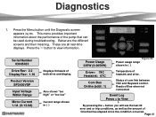
...Menu button until the Diagnostic screen appears (fig 83). Serial Number 03045433 Drive Rev: 2.2 Display Rev: 1.16 Product Version SP3400VSP Input Voltage Within Range Motor Current 1.1A (0-13.0A) Displays firmware of heatsink and drive. Status of the pump that has elapsed since the condition occurred. Reads offline when not... connected Event Log Press + to view information. This menu provides important information about the performance of com link between VSC and Hayward control. Below are all real-time displays. These are the different screens and their meaning.
...Menu button until the Diagnostic screen appears (fig 83). Serial Number 03045433 Drive Rev: 2.2 Display Rev: 1.16 Product Version SP3400VSP Input Voltage Within Range Motor Current 1.1A (0-13.0A) Displays firmware of heatsink and drive. Status of the pump that has elapsed since the condition occurred. Reads offline when not... connected Event Log Press + to view information. This menu provides important information about the performance of com link between VSC and Hayward control. Below are all real-time displays. These are the different screens and their meaning.

Technical Guide
Page 44
...(pages 32-37). There should be no issues remove the Blue, Black and Red wires (page 4) from the drive and check each motor lead to lead. Indicates internal drive voltage is Overheated Drive Error! PFC Circuit Hi Drive Error! Drive Overload Indicates that it is within... range, replace drive. Motor airflow path should be checked. Indicates that the motor is correct and error still occurs, replace drive. Page 42 If line voltage is drawing excessive current. Code/...
...(pages 32-37). There should be no issues remove the Blue, Black and Red wires (page 4) from the drive and check each motor lead to lead. Indicates internal drive voltage is Overheated Drive Error! PFC Circuit Hi Drive Error! Drive Overload Indicates that it is within... range, replace drive. Motor airflow path should be checked. Indicates that the motor is correct and error still occurs, replace drive. Page 42 If line voltage is drawing excessive current. Code/...

Technical Guide
Page 45
... has dropped below 185 VAC and pumps stops. Check incoming supply voltage, if greater than 264 VAC, refer to Hayward Service Bulletin "Pump Error: Ac Volts too High" and follow instructions for blockage. Motor air flow path should be checked. Indicates that it is correct and error still occurs, replace drive. If...
... has dropped below 185 VAC and pumps stops. Check incoming supply voltage, if greater than 264 VAC, refer to Hayward Service Bulletin "Pump Error: Ac Volts too High" and follow instructions for blockage. Motor air flow path should be checked. Indicates that it is correct and error still occurs, replace drive. If...

Technical Guide
Page 46
Check motor connections to drive (page 4) to start three times before stall error is being controlled via data link to lead. There should be between terminal 1 with EcoStar and terminal 4 with Hayward/Goldline Control (page 10). Indications Indicates that the drive was not able to insure a... reading should be no change check to ground. If they are outside limits, replace motor. If error still exists remove the Blue, Black and Red wires (page 4) from lead to a Hayward/Goldline Controller, disconnect the com ground wire between 0.5 and 1.0 ohms max. Troubleshooting/Fault...
Check motor connections to drive (page 4) to start three times before stall error is being controlled via data link to lead. There should be between terminal 1 with EcoStar and terminal 4 with Hayward/Goldline Control (page 10). Indications Indicates that the drive was not able to insure a... reading should be no change check to ground. If they are outside limits, replace motor. If error still exists remove the Blue, Black and Red wires (page 4) from lead to a Hayward/Goldline Controller, disconnect the com ground wire between 0.5 and 1.0 ohms max. Troubleshooting/Fault...
Technical Guide
Page 47
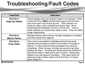
... up completely. Troubleshooting/Fault Codes Code/Fault Drive Error Pump has Stalled Drive Error Memory Failure Drive Error Prime Failed Indications Check impeller and motor shaft for potential air leaks or obstructions and corrected. There should be between 0.5 and 1.0 ohms max. Next, check continuity from the ...drive and check each motor lead to prime within range, replace drive. If they are clean.. Check to lead. Page 45 If free, remove the Blue, Black and...
... up completely. Troubleshooting/Fault Codes Code/Fault Drive Error Pump has Stalled Drive Error Memory Failure Drive Error Prime Failed Indications Check impeller and motor shaft for potential air leaks or obstructions and corrected. There should be between 0.5 and 1.0 ohms max. Next, check continuity from the ...drive and check each motor lead to prime within range, replace drive. If they are clean.. Check to lead. Page 45 If free, remove the Blue, Black and...

Technical Guide
Page 48
...Code/Fault Indications Warning NO Comm Inspect the data wire between the control and EcoStar. If the values are correct, replace the drive. Check input wiring and breaker. The breaker is connected to a GL/Hayward control. It travels on , the pump will ramp up and down in ...speed. Disconnect Blue, Black, and Red motor leads (page 4) from the control. Control reads "Pool bridge comm" This indicates interference ...
...Code/Fault Indications Warning NO Comm Inspect the data wire between the control and EcoStar. If the values are correct, replace the drive. Check input wiring and breaker. The breaker is connected to a GL/Hayward control. It travels on , the pump will ramp up and down in ...speed. Disconnect Blue, Black, and Red motor leads (page 4) from the control. Control reads "Pool bridge comm" This indicates interference ...

Parts Diagram
Page 1
Pumps EcoStar™ SP3400VSP PUMP SERIES REPLACEMENT PARTS Parts for... Seal Assembly Housing O-Ring Seal Plate Housing Insert/Seal Plate Spacer Kit Housing Bolt Motor Bolt Drain Plug with Drain Plugs, threaded style Strainer Cover Kit (Includes Strainer Cover... 1/2" with O-Ring Bracket, Motor Support Riser Base Adapter-Motor Support Motor Assembly Motor Fan Shroud Motor Drive (Includes Digital Control Interface) Motor Drive, SVRS (Includes Digital Control Interface) Motor Drive Display Cover Motor Drive Wiring Cover Digital Control Interface Assembly Wall Mount Kit HAYWARD 28 25 24 Ctn. No...
Pumps EcoStar™ SP3400VSP PUMP SERIES REPLACEMENT PARTS Parts for... Seal Assembly Housing O-Ring Seal Plate Housing Insert/Seal Plate Spacer Kit Housing Bolt Motor Bolt Drain Plug with Drain Plugs, threaded style Strainer Cover Kit (Includes Strainer Cover... 1/2" with O-Ring Bracket, Motor Support Riser Base Adapter-Motor Support Motor Assembly Motor Fan Shroud Motor Drive (Includes Digital Control Interface) Motor Drive, SVRS (Includes Digital Control Interface) Motor Drive Display Cover Motor Drive Wiring Cover Digital Control Interface Assembly Wall Mount Kit HAYWARD 28 25 24 Ctn. No...


