
EcoStar Manual
Page 18
Configuration Menu Locked Configuration Menu press > to next item Time: Th 1:27PM + change or > skip Set Day and Time Thursday 1:27p Speed Selection rpm MAX allowed speed 3450 (600-3450rpm) MIN allowed speed 600 (600-3450rpm) Set max-speed Prime Period: Auto Sense Remote Control Mode Standalone/Hayward Set COMM Bus Address Pool Filter to adjust, > go to enter Use + / -
Configuration Menu Locked Configuration Menu press > to next item Time: Th 1:27PM + change or > skip Set Day and Time Thursday 1:27p Speed Selection rpm MAX allowed speed 3450 (600-3450rpm) MIN allowed speed 600 (600-3450rpm) Set max-speed Prime Period: Auto Sense Remote Control Mode Standalone/Hayward Set COMM Bus Address Pool Filter to adjust, > go to enter Use + / -

Technical Guide
Page 3
...; All electrical wiring MUST be in conformance with all instructions in the owner's manual and on how to electric supply. Page 1 Provide a properly located electrical receptacle. Also, contact a licensed electrician for information on local electrical codes for electrocution and could result in injury or death. Failure to pool structure will increase risk for bonding requirements. Before working on drive or motor, turn off power supply to...
...; All electrical wiring MUST be in conformance with all instructions in the owner's manual and on how to electric supply. Page 1 Provide a properly located electrical receptacle. Also, contact a licensed electrician for information on local electrical codes for electrocution and could result in injury or death. Failure to pool structure will increase risk for bonding requirements. Before working on drive or motor, turn off power supply to...

Technical Guide
Page 5
Installation - Electrical Remove the electrical cover plate as shown below (fig 2, 3 & 4) Figure 2 Note: If power is removed from the pump, all settings will be protected for at least 5 years. Figure 3 Figure 4 Page 3
Installation - Electrical Remove the electrical cover plate as shown below (fig 2, 3 & 4) Figure 2 Note: If power is removed from the pump, all settings will be protected for at least 5 years. Figure 3 Figure 4 Page 3

Technical Guide
Page 7
... connected to a Hayward/Goldline control, voltage needs to come directly from a breaker in the control, or in the case of an OnCommand, directly from the main or sub-panel and not from the filter pump relay. Note: When connecting high voltage for an EcoStar that is both bonded and grounded Page 5 Electrical/High Voltage High Voltage Wiring terminals (L1 & L2) 1. Installation - It is below high voltage wires and should be determined by the NEC and local code requirements. Voltage: 230 VAC...
... connected to a Hayward/Goldline control, voltage needs to come directly from a breaker in the control, or in the case of an OnCommand, directly from the main or sub-panel and not from the filter pump relay. Note: When connecting high voltage for an EcoStar that is both bonded and grounded Page 5 Electrical/High Voltage High Voltage Wiring terminals (L1 & L2) 1. Installation - It is below high voltage wires and should be determined by the NEC and local code requirements. Voltage: 230 VAC...

Technical Guide
Page 8
Installation-Interface removal/positioning The interface assembly on the EcoStar can be configured in four different positions. 1. Reposition interface assembly as shown (fig 8). 3. Remove the interface assembly as shown (fig 7, 9, 10 & 11) and re-secure with the two screws (fig 7). Figure 7 Figure 8 Figure 9 Figure 10 Figure 11 Page 6 Remove the two screws as shown (fig 7). 2.
Installation-Interface removal/positioning The interface assembly on the EcoStar can be configured in four different positions. 1. Reposition interface assembly as shown (fig 8). 3. Remove the interface assembly as shown (fig 7, 9, 10 & 11) and re-secure with the two screws (fig 7). Figure 7 Figure 8 Figure 9 Figure 10 Figure 11 Page 6 Remove the two screws as shown (fig 7). 2.
Technical Guide
Page 10
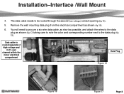
... will need to procure a six wire data cable, as short as possible, and attach the wires to the data plug as shown (fig 16). 6. Installation-Interface /Wall Mount 4. Remove the wall mounting data plug from the electrical compartment as shown (fig 17) taking care to note the color and corresponding number next to be routed through the second (low voltage) conduit opening (fig...
... will need to procure a six wire data cable, as short as possible, and attach the wires to the data plug as shown (fig 16). 6. Installation-Interface /Wall Mount 4. Remove the wall mounting data plug from the electrical compartment as shown (fig 17) taking care to note the color and corresponding number next to be routed through the second (low voltage) conduit opening (fig...

Technical Guide
Page 12
... 22 & 23). Wire colors can be run through the second (data) conduit opening and channel (Page 8). 2. Installation-Hayward/Goldline Controls (Compatible software shown below) 1. Wire 7 on the pump to 2 on the controller, 8 on the pump to 3 on the controller and 1 on 7 EcoStar is data connected to a Hayward/Goldline control, voltage needs to come directly from 4 on Remote display to 1 on the pump to 4 to the controller as they match point to operate the EcoStar Aqua Logic/Pro Logic/Aqua Plus v2.65...
... 22 & 23). Wire colors can be run through the second (data) conduit opening and channel (Page 8). 2. Installation-Hayward/Goldline Controls (Compatible software shown below) 1. Wire 7 on the pump to 2 on the controller, 8 on the pump to 3 on the controller and 1 on 7 EcoStar is data connected to a Hayward/Goldline control, voltage needs to come directly from 4 on Remote display to 1 on the pump to 4 to the controller as they match point to operate the EcoStar Aqua Logic/Pro Logic/Aqua Plus v2.65...

Technical Guide
Page 13
Installation-Relay Connected Controls (Non Hayward/Goldline compatible software & third party controls) 1. Filter Pump Replay AUX Relay AUX Relay AUX Relay Fig 24 Page 11 Pump power (230 VAC) needs to be rated for maximum voltage in the control box. Cable used for the pump (fig 24). The "Load Out" side will feed the incoming high voltage for data connections should be brought into the "line in" contacts on the Filter Pump Relay from a breaker in motor compartment.
Installation-Relay Connected Controls (Non Hayward/Goldline compatible software & third party controls) 1. Filter Pump Replay AUX Relay AUX Relay AUX Relay Fig 24 Page 11 Pump power (230 VAC) needs to be rated for maximum voltage in the control box. Cable used for the pump (fig 24). The "Load Out" side will feed the incoming high voltage for data connections should be brought into the "line in" contacts on the Filter Pump Relay from a breaker in motor compartment.

Technical Guide
Page 17
... operations. Unprotected mode requires manual verification. The & arrow buttons are used to move between displays and to select parameters to max set speed for maintenance, end a favorite speed choice or end quick clean. The & buttons are used to change the parameters. TIMERS ACTIVE LED LED will illuminate once the timers have been programmed., even if the pump is selected. QUICK CLEAN Elevates the speed of time. Pressed again the pump will stop the pump for cleaning...
... operations. Unprotected mode requires manual verification. The & arrow buttons are used to move between displays and to select parameters to max set speed for maintenance, end a favorite speed choice or end quick clean. The & buttons are used to change the parameters. TIMERS ACTIVE LED LED will illuminate once the timers have been programmed., even if the pump is selected. QUICK CLEAN Elevates the speed of time. Pressed again the pump will stop the pump for cleaning...

Technical Guide
Page 23
Press the button to toggle between Stand alone/Hayward (Stand alone or Hayward/Goldline compatible software controls), or Relay Control (other controls including third party models) (fig 43 & 44). Press & buttons for Auto Sense (3000 RPM), or a 3 min (max set speed) prime period (fig 42).This function only works in Standalone and Relay Control modes. Use the & buttons to continue. 12. You will now see the Remote Control Mode screen. Press the button to continue . You will now see the max-speed Prime period. Fig 42 Fig 43 Fig 44 Page 21 Programming-Configuration 11.
Press the button to toggle between Stand alone/Hayward (Stand alone or Hayward/Goldline compatible software controls), or Relay Control (other controls including third party models) (fig 43 & 44). Press & buttons for Auto Sense (3000 RPM), or a 3 min (max set speed) prime period (fig 42).This function only works in Standalone and Relay Control modes. Use the & buttons to continue. 12. You will now see the Remote Control Mode screen. Press the button to continue . You will now see the max-speed Prime period. Fig 42 Fig 43 Fig 44 Page 21 Programming-Configuration 11.
Technical Guide
Page 32
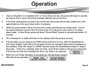
... start unless one or more timers are using is an SVRS model and there is activated you are set, the pump will show on the interface. Auto Prime and the 3 minute prime only works in watts will go into the prime mode selected during operation Monday 1:30p 2500 RPM 2000 Watts Low Temp Operation 2500 RPM 2000 Watts Page 30 Operation 1. If the error message does not clear...
... start unless one or more timers are using is an SVRS model and there is activated you are set, the pump will show on the interface. Auto Prime and the 3 minute prime only works in watts will go into the prime mode selected during operation Monday 1:30p 2500 RPM 2000 Watts Low Temp Operation 2500 RPM 2000 Watts Page 30 Operation 1. If the error message does not clear...

Technical Guide
Page 33
... 3 seconds after adjusting speed will lock in the new speed setting. It will go to the speed and duration that was set speed for cleaning. Disables SVRS if included with the SVRS models. Pressing the „+‟ or‟-‟ key during a speed choice will illuminate indicating the pump has stopped. CHECK SYSTEM LED LED will illuminate once the timers have been programmed. Operation Display Screen Fig 62 STOP...
... 3 seconds after adjusting speed will lock in the new speed setting. It will go to the speed and duration that was set speed for cleaning. Disables SVRS if included with the SVRS models. Pressing the „+‟ or‟-‟ key during a speed choice will illuminate indicating the pump has stopped. CHECK SYSTEM LED LED will illuminate once the timers have been programmed. Operation Display Screen Fig 62 STOP...

Technical Guide
Page 44
... ground. Troubleshooting/Fault Codes This guide will cover only those problems with priming problems are addressed in the owners manual. Check incoming line voltage (page 4) and verify that the motor is too high. Page 42 Drive Overload Indicates that the internal components of the drive (page 36). If error still occurs, replace drive. Indicates internal drive voltage is drawing excessive current. Ohms readings should be no issues remove the...
... ground. Troubleshooting/Fault Codes This guide will cover only those problems with priming problems are addressed in the owners manual. Check incoming line voltage (page 4) and verify that the motor is too high. Page 42 Drive Overload Indicates that the internal components of the drive (page 36). If error still occurs, replace drive. Indicates internal drive voltage is drawing excessive current. Ohms readings should be no issues remove the...

Technical Guide
Page 45
... registry change . If line voltage is correct and error still occurs, replace drive. Clear all debris from the heatsink (page 36) on the bottom of 230 VAC. If error still occurs, replace drive. Page 43 Troubleshooting/Fault Codes Code/Fault Drive Error! If line voltage is too low. Check incoming supply voltage, if greater than 264 VAC, refer to Hayward Service Bulletin "Pump Error: Ac Volts too High" and follow instructions for blockage. Motor air flow path should be checked. Indicates...
... registry change . If line voltage is correct and error still occurs, replace drive. Clear all debris from the heatsink (page 36) on the bottom of 230 VAC. If error still occurs, replace drive. Page 43 Troubleshooting/Fault Codes Code/Fault Drive Error! If line voltage is too low. Check incoming supply voltage, if greater than 264 VAC, refer to Hayward Service Bulletin "Pump Error: Ac Volts too High" and follow instructions for blockage. Motor air flow path should be checked. Indicates...

Technical Guide
Page 46
... be no change check to insure other data wires are outside limits, replace motor. If any of these readings are connected correctly (page 10). Troubleshooting/Fault Codes Code/Fault Drive Error Drive failed to insure a good connection. Check to a Hayward/Goldline Controller, disconnect the com ground wire between 0.5 and 1.0 ohms max. Check continuity from the drive and check each motor lead to start the motor. If no continuity. If error still exists remove all (0) check connection between interface...
... be no change check to insure other data wires are outside limits, replace motor. If any of these readings are connected correctly (page 10). Troubleshooting/Fault Codes Code/Fault Drive Error Drive failed to insure a good connection. Check to a Hayward/Goldline Controller, disconnect the com ground wire between 0.5 and 1.0 ohms max. Check continuity from the drive and check each motor lead to start the motor. If no continuity. If error still exists remove all (0) check connection between interface...

Technical Guide
Page 47
... drive and check each motor lead to prime within range, replace drive. In many instances the pump basket may not fill up completely. Plumbing and fittings should be between 0.5 and 1.0 ohms max. Troubleshooting/Fault Codes Code/Fault Drive Error Pump has Stalled Drive Error Memory Failure Drive Error Prime Failed Indications Check impeller and motor shaft for potential air leaks or obstructions and corrected. Indicates the pump was not able to ground. If free, remove the...
... drive and check each motor lead to prime within range, replace drive. In many instances the pump basket may not fill up completely. Plumbing and fittings should be between 0.5 and 1.0 ohms max. Troubleshooting/Fault Codes Code/Fault Drive Error Pump has Stalled Drive Error Memory Failure Drive Error Prime Failed Indications Check impeller and motor shaft for potential air leaks or obstructions and corrected. Indicates the pump was not able to ground. If free, remove the...

Technical Guide
Page 48
... values are at "0" replace the interface. EcoStar is caused by frequency noise emitted from the control. This is connected to a GL/Hayward control. Install RS485 isolator, or new interface v2.55 rev. 1.1. Check input wiring and breaker. Disconnect Blue, Black, and Red motor leads (page 4) from the display and re-connect. ground between the interface and drive. If not, replace motor. If still tripping breaker, replace drive. Page 46...
... values are at "0" replace the interface. EcoStar is caused by frequency noise emitted from the control. This is connected to a GL/Hayward control. Install RS485 isolator, or new interface v2.55 rev. 1.1. Check input wiring and breaker. Disconnect Blue, Black, and Red motor leads (page 4) from the display and re-connect. ground between the interface and drive. If not, replace motor. If still tripping breaker, replace drive. Page 46...

Technical Guide
Page 49
... line or load side of the filter pump relay in the control (page 20) EcoStar reverts to Standalone mode even when properly connected to not interfere with a GL/Hayward control. Be sure EcoStar is configured for relay control (page 10) . The %/rpm reading does not match between GL/Hayward control and EcoStar. Check comm. Page 47 No connections are on control display. No error on the EcoStar comm. Troubleshooting/Fault Codes Code/Fault Indications EcoStar is connected and configured...
... line or load side of the filter pump relay in the control (page 20) EcoStar reverts to Standalone mode even when properly connected to not interfere with a GL/Hayward control. Be sure EcoStar is configured for relay control (page 10) . The %/rpm reading does not match between GL/Hayward control and EcoStar. Check comm. Page 47 No connections are on control display. No error on the EcoStar comm. Troubleshooting/Fault Codes Code/Fault Indications EcoStar is connected and configured...

Technical Guide
Page 50
... Quick Clean button is sent to the pump, the EcoStar interface reads "Remote Stop Engaged". If problem persists, purchase (2) model XPF 20A 3-wire noise filters through X-10 website. This indicates that the comm. The Speed buttons and Quick Clean buttons on and off. Try changing channel on the drive (page 10). Page 48 This is actually for relay control. Remove wires and connect to operate via the GL/Hayward control. Troubleshooting/Fault Codes Code/Fault Indications...
... Quick Clean button is sent to the pump, the EcoStar interface reads "Remote Stop Engaged". If problem persists, purchase (2) model XPF 20A 3-wire noise filters through X-10 website. This indicates that the comm. The Speed buttons and Quick Clean buttons on and off. Try changing channel on the drive (page 10). Page 48 This is actually for relay control. Remove wires and connect to operate via the GL/Hayward control. Troubleshooting/Fault Codes Code/Fault Indications...

Parts Diagram
Page 1
NOT Pressure Testable) Strainer Cover O-Ring Strainer Basket Diffuser Screw Diffuser O-Ring Diffuser Impeller Screw Impeller Ring Impeller with Impeller Screw Shaft Seal Assembly Housing O-Ring Seal Plate Housing Insert/Seal Plate Spacer Kit Housing Bolt Motor Bolt Drain Plug with Drain Plugs, threaded style Strainer Cover Kit (Includes Strainer Cover, Lock Ring, O-Ring) Strainer Cover Kit (Biguanide Sanitizer Applications Only; SPX3200UNKIT SPX3200UG SPX3200A SPX3200DLS SPX3200DLSB SPX3200S SPX3200M SPX3200Z8 SPX4000Z1 SPX3200B3 SPX3200Z1 SPX3021R SPX3220C SPX3200SA SPX3200T SPX3200E ...
NOT Pressure Testable) Strainer Cover O-Ring Strainer Basket Diffuser Screw Diffuser O-Ring Diffuser Impeller Screw Impeller Ring Impeller with Impeller Screw Shaft Seal Assembly Housing O-Ring Seal Plate Housing Insert/Seal Plate Spacer Kit Housing Bolt Motor Bolt Drain Plug with Drain Plugs, threaded style Strainer Cover Kit (Includes Strainer Cover, Lock Ring, O-Ring) Strainer Cover Kit (Biguanide Sanitizer Applications Only; SPX3200UNKIT SPX3200UG SPX3200A SPX3200DLS SPX3200DLSB SPX3200S SPX3200M SPX3200Z8 SPX4000Z1 SPX3200B3 SPX3200Z1 SPX3021R SPX3220C SPX3200SA SPX3200T SPX3200E ...


