Hayward EcoStar Support Question
Hayward EcoStar Support Question
Find answers below for this question about Hayward EcoStar.Need a Hayward EcoStar manual? We have 3 online manuals for this item!
Question posted by brBro on January 25th, 2014
How To Prevent Prime Pool Pump Hayward Ecostar
The person who posted this question about this Hayward product did not include a detailed explanation. Please use the "Request More Information" button to the right if more details would help you to answer this question.
Current Answers
Related Hayward EcoStar Manual Pages
EcoStar Manual - Page 17
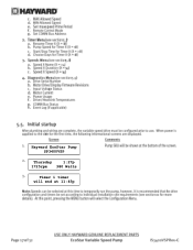
Hayward EcoStar Pump SP3400VSP
Thursday
1:27p
1725rpm 380 Watts
Timer 1 timer will end at 11:45p
EcoStar Manual - Page 18

to adjust, > go to enter
Use + / - Configuration Menu Locked
Configuration Menu press > to next item Time: Th 1:27PM
+ change or > skip
Set Day and Time Thursday 1:27p
Speed Selection rpm
MAX allowed speed 3450 (600-3450rpm)
MIN allowed speed 600 (600-3450rpm)
Set max-speed Prime Period: Auto Sense
Remote Control Mode Standalone/Hayward
Set COMM Bus Address Pool Filter
Technical Guide - Page 1
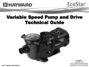
Variable Speed Pump and Drive Technical Guide
© 2011 Hayward Pool Products
Version 2 Drive FW 1.02 Interface FW 2.55 residential Interface FW 1.00 commercial
Technical Guide - Page 4

...
* Refer to insure the maximum flow does not exceed the capacity of pipe (L) between pump suction port and first elbow or fitting should be at least 5 times pipe size. Installation -
Existing Pools: When installing the EcoStar on a new pool, care should be taken to ensure proper pipe and equipment sizing to handle the maximum...
Technical Guide - Page 7

...Hayward/Goldline control, voltage needs to come directly from a breaker in the control, or in the case of an OnCommand, directly from the main or sub-panel and not from the filter pump... high voltage and the other for an EcoStar that is both bonded and grounded
Page 5 Ground Wire Terminal.
Figure 6
Conduit Connections
There are two on the pump.
Breaker, wire size would be connected ...
Technical Guide - Page 12

... the control, or in units
8
Mfg 5/19/11
1 going forward
Figure 23
Pump Terminal Data Plugs
Page 10 Note: When connecting high voltage for data cable The data...the main or sub- Maximum 500‟ for an EcoStar that is not
needed in the case of an OnCommand, directly from
4 on
7
EcoStar is data connected to a Hayward/Goldline control, voltage
needs to
the controller as they ...
Technical Guide - Page 13

...
AUX Relay
Fig 24 Page 11 Cable used for data connections should be brought into the "line in" contacts on the Filter Pump Relay from a breaker in motor compartment. Pump power (230 VAC) needs to be rated for the pump (fig 24). Installation-Relay Connected Controls
(Non Hayward/Goldline compatible software & third party controls)
1.
Technical Guide - Page 14

... Relay
Fig 25 Page 12
Installation-Relay Connected Controls
(Non Hayward/Goldline compatible software & third party controls)
2. 1, 3 and 5 from the pump terminal needs to be wired to the Load side of the relays in series as shown (fig
wired with 2, 4 & 6 on the pump terminal as shown (fig 25). One side of the 24...
Technical Guide - Page 15

...sequence of aux relays used.
Filter pump relay plus 2 aux relays allows control of 2 speeds
Filter Pump Relay
1st Aux (1)
Timer 1 ...Speed
On
Off
Timer 2 Speed
On
On
Fig 28
Page 13 As shown by the charts, the number of speeds available depends on the number of off and on the pump for each relay. Installation-Relay Connected Controls
(Non Hayward...
Technical Guide - Page 23

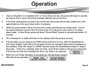
.... Press & buttons for Auto Sense (3000 RPM), or a 3 min (max set speed) prime period (fig 42).This function only works in Standalone and Relay Control modes.
Press the button to toggle between Stand alone/Hayward (Stand alone or Hayward/Goldline compatible software controls), or Relay Control (other controls including third party models) (fig...
Technical Guide - Page 24

... or higher will give you 9 address choices. For EcoStar interface software v2.55 data linked to be set, as all settings will be handled in the control. The Goldline/Hayward controller will only recognize address 1 (Pool Filter) and address 2 (Aux 1/ Spa Filter).
Note: In the Hayward/Goldline compatible software mode the timers do not need...
Technical Guide - Page 27

.... Press the button until you see the Timers Menu (fig 51). Timer 1 will start and stop pump. Note: All speed settings in the timer menu are limited to 11:45 pm (fig 52). This.... Timer 1 can be changed as relays on control connected pumps.
Com bus address needs to be set.
Programming-Timers
Stand alone/Hayward Stand alone:
Both times and speeds need to be set.
Technical Guide - Page 32
... works in watts will show "Prime Failed" if prime is activated you are set, the pump will not start unless one or more timers are using is an SVRS model and there is running.
5. If the EcoStar you will be replaced. 6. Clear the reason for SVRS Trip then press the Stop/Resume button to...
Technical Guide - Page 35
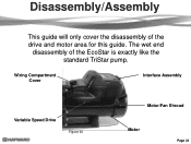
The wet end
disassembly of the drive and motor area for this guide. Wiring Compartment Cover
Interface Assembly
Variable Speed Drive
Figure 63
Motor/Fan Shroud
Motor
Page 33
Disassembly/Assembly
This guide will only cover the disassembly of the EcoStar is exactly like the standard TriStar pump.
Technical Guide - Page 43
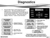
... last 20
error and or trip conditions, as well as the amount of com link between VSC and Hayward control.
Also shows "too high" or "too low" Current range shown in ( )
Power Usage ...range shown in ( )
Driver: 78C Heatsink: 67C
Com Bus Online (addr: 1)
Temperature of the pump that has elapsed since the condition occurred.
Reads offline when not connected
Event Log Press + to view ...
Technical Guide - Page 46

... interface and drive. Troubleshooting/Fault Codes
Code/Fault
Drive Error Drive failed to lead. Ohms reading should be between terminal 1 with EcoStar and terminal 4 with Hayward/Goldline Control (page 10). If pump is displayed.
Check continuity from the drive and check each motor lead to insure a good connection. Page 44 There should be...
Technical Guide - Page 48

...connected to a GL/Hayward control. If still tripping breaker, replace drive. Troubleshooting/Fault Codes
Code/Fault
Indications
Warning NO Comm
Inspect the data wire between the control and EcoStar. EcoStar is tripping.
If...Disconnect the wires from the pump drive. ground between the interface and drive. Control reads "Pool bridge comm"
This indicates interference on the comm.
Technical Guide - Page 49

... with the settings in Standalone mode.
The %/rpm reading does not match between GL/Hayward control and EcoStar. Check the settings in the control (page 5).
The EcoStar should be wired to variable speed . Check comm. wires between the
pump interface and the control
Check to make sure the Min and Max setting on in...
Technical Guide - Page 50

... and should not be expected to operate via the GL/Hayward control.
This indicates that the comm. Troubleshooting/Fault Codes
Code/Fault
Indications
The freeze protection in the EcoStar to the pump, the
EcoStar interface reads "Remote Stop Engaged".
bus plug on X-10.
The EcoStar is experiencing interference with an X-10 home automation control and...
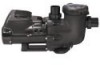
Parts Diagram - Page 1

... Kit (Includes Union Nut, Union Connector, Union Gasket - 2 ea.) Union Gasket Pump Strainer Housing, 2" x 2 1/2" with O-Ring Bracket, Motor Support Riser Base Adapter... Motor Drive Wiring Cover Digital Control Interface Assembly Wall Mount Kit
HAYWARD
28
25
24
Ctn. Pumps
EcoStar™
SP3400VSP PUMP SERIES REPLACEMENT PARTS
Parts for Pump Models: SP3400VSP, SP3400VSPVR
4 5 6
10 11
3
78 ...
Similar Questions


How To Reset Default Settings On Hayward Ecostar Pool Pump
(Posted by ronaqw 10 years ago)


How To Clean And Close Hayward Self-priming Super Pump
(Posted by Guidobil 10 years ago)

Dual Pool Spa System But The Settings Menu Doesn't Show Pool Heater Only Spa Hea
(Posted by Anonymous-39619 12 years ago)