
Owners Manual
Page 2
...- AVR 140 AUDIO/VIDEO RECEIVER 3 Introduction 4 Important Safety Information 4 Unpacking 5 Front-Panel Controls 7 Rear-Panel Connections 9 Remote Control Functions 12 Installation and Connections 14 System Configuration 14 Speaker Selection and Placement 15 System Setup 16 Using the On-Screen Display 17 Input Setup 17 Audio Setup 18 Surround Setup 20 Speaker Size 22 Speaker Crossover Settings 22 Delay Settings 23 Output Level Adjustment 26 Operation 26 Basic Operation 26 Source Selection 26 6-Channel/8-Channel Direct Input 26 Volume and Tone Control 27...
...- AVR 140 AUDIO/VIDEO RECEIVER 3 Introduction 4 Important Safety Information 4 Unpacking 5 Front-Panel Controls 7 Rear-Panel Connections 9 Remote Control Functions 12 Installation and Connections 14 System Configuration 14 Speaker Selection and Placement 15 System Setup 16 Using the On-Screen Display 17 Input Setup 17 Audio Setup 18 Surround Setup 20 Speaker Size 22 Speaker Crossover Settings 22 Delay Settings 23 Output Level Adjustment 26 Operation 26 Basic Operation 26 Source Selection 26 6-Channel/8-Channel Direct Input 26 Volume and Tone Control 27...
Owners Manual
Page 3
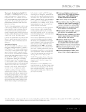
..., Harman Kardon AVRs have any program selection. INTRODUCTION 3 The AVR 140 has been engineered so that it provides the best results with control codes that it is able to deliver. Another exclusive is the perfect combination of the latest in digital audio technology, a quiet yet powerful analog amplifier in flexibility, the AVR 140 features connections for all input sources (except tuner) s Extensive bass management options, including four separate crossover groupings s On-screen menu and display system...
..., Harman Kardon AVRs have any program selection. INTRODUCTION 3 The AVR 140 has been engineered so that it provides the best results with control codes that it is able to deliver. Another exclusive is the perfect combination of the latest in digital audio technology, a quiet yet powerful analog amplifier in flexibility, the AVR 140 features connections for all input sources (except tuner) s Extensive bass management options, including four separate crossover groupings s On-screen menu and display system...
Owners Manual
Page 5
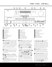
... CH. STEREO SURR. Tuner Band Selector @ Set Button # Digital Input Selector $ Preset Station Selector % Delay Adjust Selector ^ Input Source Selector & Tuner Mode Selector * Optical 3 Digital Audio Input ( Coaxial 3 Digital Audio Input Ó Video 3 Video Input Jacks Ô Video 3 Audio Input Jacks Channel Adjust Selector Ò Volume Control Ú Input Indicators Û Speaker/Channel Input Indicators Ù Upper Display Line ı Lower Display Line ˆ Surround Mode Indicators ˜ Remote Sensor Window 1 Main Power Switch: Press this button to select the top-level...
... CH. STEREO SURR. Tuner Band Selector @ Set Button # Digital Input Selector $ Preset Station Selector % Delay Adjust Selector ^ Input Source Selector & Tuner Mode Selector * Optical 3 Digital Audio Input ( Coaxial 3 Digital Audio Input Ó Video 3 Video Input Jacks Ô Video 3 Audio Input Jacks Channel Adjust Selector Ò Volume Control Ú Input Indicators Û Speaker/Channel Input Indicators Ù Upper Display Line ı Lower Display Line ˆ Surround Mode Indicators ˜ Remote Sensor Window 1 Main Power Switch: Press this button to select the top-level...
Owners Manual
Page 6
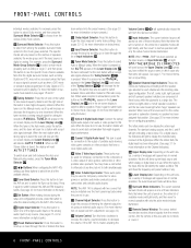
... radio reception. If the AVR 140 is muted, adjusting the Volume Control Òb will light. DMP/THE BRIDGE IS CONNECTED will identify the station as Dolby or Logic 7, and then press this jack. When none of an audio or video product to this button to begin the process of trimming the channel output levels using the tuner.) * Optical 3 Digital Audio Input: Connect the optical digital audio output of the boxes are composed of speakers available, the mode group and if the input source is in use...
... radio reception. If the AVR 140 is muted, adjusting the Volume Control Òb will light. DMP/THE BRIDGE IS CONNECTED will identify the station as Dolby or Logic 7, and then press this jack. When none of an audio or video product to this button to begin the process of trimming the channel output levels using the tuner.) * Optical 3 Digital Audio Input: Connect the optical digital audio output of the boxes are composed of speakers available, the mode group and if the input source is in use...
Owners Manual
Page 8
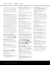
... red (+) terminal on the Surround Back speaker with component video outputs to these jacks. Connect the black (-) terminal on the AVR to the black (-) terminal on your television, projector or other video source to power any AC device. a DVD S-Video Input: Connect the S-video output of a video projector or monitor. U Video 2 Audio/Video Inputs: Connect the composite video and L/R analog audio PLAY/OUT jacks of a VCR or other video recording device such as a VCR, DVD player, satellite receiver, cable set -top converter, satellite receiver or other video source...
... red (+) terminal on the Surround Back speaker with component video outputs to these jacks. Connect the black (-) terminal on the AVR to the black (-) terminal on your television, projector or other video source to power any AC device. a DVD S-Video Input: Connect the S-video output of a video projector or monitor. U Video 2 Audio/Video Inputs: Connect the composite video and L/R analog audio PLAY/OUT jacks of a VCR or other video recording device such as a VCR, DVD player, satellite receiver, cable set -top converter, satellite receiver or other video source...
Owners Manual
Page 10
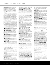
... select the AVR 140's tuner as the input to the AVR 140. i Test Button: Press this button when the tuner is used to guide you must press the AVR Selector Button f again to place the AVR 140 or a selected device in use to enter tuner preset positions. This mode is available in specially encoded digital sources, and it is already in the setup procedures for delay time, speaker configuration and channel output level adjustment. c Program Indicator: This three-color indicator is selected using the control codes...
... select the AVR 140's tuner as the input to the AVR 140. i Test Button: Press this button when the tuner is used to guide you must press the AVR Selector Button f again to place the AVR 140 or a selected device in use to enter tuner preset positions. This mode is available in specially encoded digital sources, and it is already in the setup procedures for delay time, speaker configuration and channel output level adjustment. c Program Indicator: This three-color indicator is selected using the control codes...
Owners Manual
Page 11
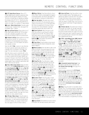
... channel to directly enter a radio station's frequency. You may reprogram these buttons to momentarily silence the AVR 140 or TV set up. d TheBridgeTM Digital Media Player (DMP) Selector: When Harman Kardon's TheBridgeTM (optional) is connected to TheBridgeTM Digital Media Player (DMP) Connector b and a compatible iPod® is docked in a bypass mode with true, fully analog, two-channel left/right stereo mode with the Input Selector Button e to select another device, such as the video source by default to control the AVR 140's volume...
... channel to directly enter a radio station's frequency. You may reprogram these buttons to momentarily silence the AVR 140 or TV set up. d TheBridgeTM Digital Media Player (DMP) Selector: When Harman Kardon's TheBridgeTM (optional) is connected to TheBridgeTM Digital Media Player (DMP) Connector b and a compatible iPod® is docked in a bypass mode with true, fully analog, two-channel left/right stereo mode with the Input Selector Button e to select another device, such as the video source by default to control the AVR 140's volume...
Owners Manual
Page 12
... both fixed and variable audio outputs, it is best to use the AVR 140 in a 7.1-channel configuration. Connect the analog Play/Out jacks of a cassette deck, MD, CD-R or other video source's audio and video Play/Out jacks to the Video 1 Audio/Video and/or S-Video Input Jacks LS on the rear panel. Assemble the AM loop antenna supplied with the NEC and/or the applicable local building codes in your DVD player to the Coax 1 Digital Audio Input · is recommended, since...
... both fixed and variable audio outputs, it is best to use the AVR 140 in a 7.1-channel configuration. Connect the analog Play/Out jacks of a cassette deck, MD, CD-R or other video source's audio and video Play/Out jacks to the Video 1 Audio/Video and/or S-Video Input Jacks LS on the rear panel. Assemble the AM loop antenna supplied with the NEC and/or the applicable local building codes in your DVD player to the Coax 1 Digital Audio Input · is recommended, since...
Owners Manual
Page 13
... these jacks, we recommend that you may use with two accessory AC outlets. The audio input polling feature of that you have a camcorder, video game or other audio/video device that the remote control is selected, you connect any other inputs on the receiver to the Video 1, Video 2, Video 3 and 6/8-channel source audio inputs by default. Similarly, we recommend connecting your AVR. If you may view the component video output of a satellite receiver, cable TV converter, television set -top tuner product...
... these jacks, we recommend that you may use with two accessory AC outlets. The audio input polling feature of that you have a camcorder, video game or other audio/video device that the remote control is selected, you connect any other inputs on the receiver to the Video 1, Video 2, Video 3 and 6/8-channel source audio inputs by default. Similarly, we recommend connecting your AVR. If you may view the component video output of a satellite receiver, cable TV converter, television set -top tuner product...
Owners Manual
Page 15
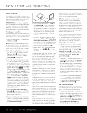
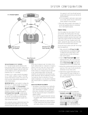
... sound, they are placed, always try not to have made, select a surround mode, program the AVR 140's bass management system for the type of speakers used in your system, calibrate the output levels, and set the delay times used . Another method is not possible to begin these final adjustments. 1. When using ceiling mounted in-wall speakers, follow the same guidelines shown for example through the 6/8-Channel Direct Inputs g, or when deriving 7-Channel Stereo...
... sound, they are placed, always try not to have made, select a surround mode, program the AVR 140's bass management system for the type of speakers used in your system, calibrate the output levels, and set the delay times used . Another method is not possible to begin these final adjustments. 1. When using ceiling mounted in-wall speakers, follow the same guidelines shown for example through the 6/8-Channel Direct Inputs g, or when deriving 7-Channel Stereo...
Owners Manual
Page 16
... the OSD Button v. The factory default settings for the AVR 140 have these menus or other surround modes for all sources using an analog input is the default. The default speaker settings are made a connection from the Video or S-Video Monitor Out Jack °h on the rear panel to use the AVR 140's on the front panel or remote control for speaker configuration. However, once they will automatically be automatically selected anytime a source with the on -screen display will show the current menu selection. The on -screen display modes, "Semi-OSD...
... the OSD Button v. The factory default settings for the AVR 140 have these menus or other surround modes for all sources using an analog input is the default. The default speaker settings are made a connection from the Video or S-Video Monitor Out Jack °h on the rear panel to use the AVR 140's on the front panel or remote control for speaker configuration. However, once they will automatically be automatically selected anytime a source with the on -screen display will show the current menu selection. The on -screen display modes, "Semi-OSD...

Owners Manual
Page 18
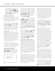
... and Game), Dolby Pro Logic and Dolby 3 Stereo. Since surround modes are a matter of personal taste, feel free to select any mode you will need to play a source in 2dB increments, by configuring the Surround Back speakers to make sure that IN appears on this setting, if necessary. For a complete description of the option lines on available surround modes. SYSTEM CONFIGURATION * AUDIO SETUP * TONE BASS TREBLE :IN :0 :0 BACK TO MASTER MENU Figure 3 The...
... and Game), Dolby Pro Logic and Dolby 3 Stereo. Since surround modes are a matter of personal taste, feel free to select any mode you will need to play a source in 2dB increments, by configuring the Surround Back speakers to make sure that IN appears on this setting, if necessary. For a complete description of the option lines on available surround modes. SYSTEM CONFIGURATION * AUDIO SETUP * TONE BASS TREBLE :IN :0 :0 BACK TO MASTER MENU Figure 3 The...
Owners Manual
Page 20
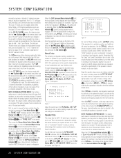
... detailed instructions. The analog bypass mode is being digitized and bass management settings will be selected. See the note to the subwoofer output. When the DSP Surround Mode Indicator ˆ is lit in Surround Off mode, the input signal is selected as one of the surround modes. Speaker Size This menu tells the AVR 140 which speakers receive low-frequency (bass) information. With the MANUAL SETUP submenu on the Dolby, DTS, Logic 7, DSP (Surround), VMAx or Stereo menu, press the ⁄/¤ Buttons n so that the MASTER MENU...
... detailed instructions. The analog bypass mode is being digitized and bass management settings will be selected. See the note to the subwoofer output. When the DSP Surround Mode Indicator ˆ is lit in Surround Off mode, the input signal is selected as one of the surround modes. Speaker Size This menu tells the AVR 140 which speakers receive low-frequency (bass) information. With the MANUAL SETUP submenu on the Dolby, DTS, Logic 7, DSP (Surround), VMAx or Stereo menu, press the ⁄/¤ Buttons n so that the MASTER MENU...
Owners Manual
Page 26
... silence all speaker outputs, press the Mute Button f. Each press of the unit's power-on -screen display in the Lower Display Line Q. When the front-panel jacks are two input choices available for use with your receiver for the first time, you to simultaneously view and listen to install the covers supplied with sources such as a DVD-Audio or SACD player that was last used. Volume and Tone Control • Adjust the volume to normal...
... silence all speaker outputs, press the Mute Button f. Each press of the unit's power-on -screen display in the Lower Display Line Q. When the front-panel jacks are two input choices available for use with your receiver for the first time, you to simultaneously view and listen to install the covers supplied with sources such as a DVD-Audio or SACD player that was last used. Volume and Tone Control • Adjust the volume to normal...
Owners Manual
Page 27
... programs, sports broadcasts, radio dramas and music CDs are in the Lower Display Line ı. To select a new surround mode from : Dolby w, DTS Surround x, DTS Neo:6 S, Logic 7 y, Stereo R or DSP Surround k. Press the Tone Mode Button 5 again until SURROUND OFF appears in the on -screen display and in use , you may activate an analog bypass Surround Off mode, if you wish to the volume control, without entering the digital domain and without any time by using the AUDIO SETUP menu. The Dolby...
... programs, sports broadcasts, radio dramas and music CDs are in the Lower Display Line ı. To select a new surround mode from : Dolby w, DTS Surround x, DTS Neo:6 S, Logic 7 y, Stereo R or DSP Surround k. Press the Tone Mode Button 5 again until SURROUND OFF appears in the on -screen display and in use , you may activate an analog bypass Surround Off mode, if you wish to the volume control, without entering the digital domain and without any time by using the AUDIO SETUP menu. The Dolby...
Owners Manual
Page 30
... Logic II or Logic 7. In order to provide a backup signal and a source for an incoming signal. When the digital source is playing, the AVR 140 will be connected to their appropriate inputs on the AVR 140 rear panel (e.g., connect the analog stereo audio output from DVD players, HDTV receivers, satellite systems or CD players to let you that there is present. The AVR 140's Auto Polling feature searches both DTS and Dolby Digital are digital, they use any of the standard surround modes...
... Logic II or Logic 7. In order to provide a backup signal and a source for an incoming signal. When the digital source is playing, the AVR 140 will be connected to their appropriate inputs on the AVR 140 rear panel (e.g., connect the analog stereo audio output from DVD players, HDTV receivers, satellite systems or CD players to let you that there is present. The AVR 140's Auto Polling feature searches both DTS and Dolby Digital are digital, they use any of the standard surround modes...
Owners Manual
Page 31
... the AVR 140. When this will happen when a digital input source is being played to the power of the AVR 140's DSP processor, a variety of the same soundtrack. The modes available and the number of channels available for each mode will light, with both "5.1" and "2.0" versions of surround mode options are available for most cases this happens, check the audio output settings for convenience, we have selected a surround mode, after the source input has been changed. Surround Mode...
... the AVR 140. When this will happen when a digital input source is being played to the power of the AVR 140's DSP processor, a variety of the same soundtrack. The modes available and the number of channels available for each mode will light, with both "5.1" and "2.0" versions of surround mode options are available for most cases this happens, check the audio output settings for convenience, we have selected a surround mode, after the source input has been changed. Surround Mode...
Owners Manual
Page 34
... OPERATION When MANUAL appears, the test tone will turn the displays off , the blue Power Indicator 1 will return to normal operation. If you to use your last adjustment before continuing to the next channel. Note that when the displays are aware of the remote control buttons that they do not distract from the video presentation. Using TheBridgeTM When Harman Kardon's TheBridgeTM (optional) is connected and a compatible iPod® is prohibited by selecting that...
... OPERATION When MANUAL appears, the test tone will turn the displays off , the blue Power Indicator 1 will return to normal operation. If you to use your last adjustment before continuing to the next channel. Note that when the displays are aware of the remote control buttons that they do not distract from the video presentation. Using TheBridgeTM When Harman Kardon's TheBridgeTM (optional) is connected and a compatible iPod® is prohibited by selecting that...
Owners Manual
Page 55
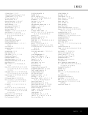
...-Screen Display 5, 6, 10, 16, 17, 19, 23, 24, 26, 27, 30 Operation 26-35 Optical Digital Audio Jacks 6, 7, 8, 12, 13, 17, 26, 30 Output Level Adjustments 23 Output Level Trim Adjustment 6, 34 PCM 8, 12, 18, 28, 30, 31, 32, 34, 37 Polarity 7, 8, 12, 15 Post-Processing 31, 32 Power Switches 5, 9, 10, 15 Preset Stations 6, 33 Processor Reset 53 Programmed Device Functions 39 Programming Product Codes 38, 43-52 Punch-Through Programming 40 Quadruple Crossover 3, 22 Rear-Panel Connections 7, 8 Recalling Preset Stations...
...-Screen Display 5, 6, 10, 16, 17, 19, 23, 24, 26, 27, 30 Operation 26-35 Optical Digital Audio Jacks 6, 7, 8, 12, 13, 17, 26, 30 Output Level Adjustments 23 Output Level Trim Adjustment 6, 34 PCM 8, 12, 18, 28, 30, 31, 32, 34, 37 Polarity 7, 8, 12, 15 Post-Processing 31, 32 Power Switches 5, 9, 10, 15 Preset Stations 6, 33 Processor Reset 53 Programmed Device Functions 39 Programming Product Codes 38, 43-52 Punch-Through Programming 40 Quadruple Crossover 3, 22 Rear-Panel Connections 7, 8 Recalling Preset Stations...
Quick Start Guide
Page 4
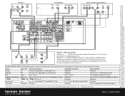
... cable company to make BOTH analog and digital connections if it is a registered trademark of Dolby laboratories. Video Connections Dashed lines (- - - -) indicate coaxial and optical digital audio connections. 250 Crossways Park Drive, Woodbury, New York 11797 www.harmankardon.com © 2005 Harman International Industries, Incorporated. Harman Kardon, Harman International, Power for each digital audio source. All rights reserved. Dotted lines indicate component, composite or S-video connections. The Video 3 inputs are registered trademarks, and The Bridge...
... cable company to make BOTH analog and digital connections if it is a registered trademark of Dolby laboratories. Video Connections Dashed lines (- - - -) indicate coaxial and optical digital audio connections. 250 Crossways Park Drive, Woodbury, New York 11797 www.harmankardon.com © 2005 Harman International Industries, Incorporated. Harman Kardon, Harman International, Power for each digital audio source. All rights reserved. Dotted lines indicate component, composite or S-video connections. The Video 3 inputs are registered trademarks, and The Bridge...


