Manual
Page 3
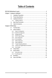
Table of Contents MZJ19AI Motherboard Layout 4 Chapter 1 Hardware Installation 6 1-1 Installation Precautions 6 1-2 Product Specifications 7 1-3 Installing the Memory 9 1-3-1 Installing a Memory 9 1-4 Back Panel Connectors 10 1-5 Internal Connectors 12 Chapter 2 BIOS Setup 21 2-1 The Main Menu 23 2-2 Advanced Menu 25 2-2-1 Super IO Configuration 26 2-2-1-1 Serial Port Configuration 27 2-2-2 Hardware Monitor 28 2-2-3 S5 RTC Wake Settings 29 2-2-4 CPU Configuration 30 2-2-4-1 CPU Information...31 2-2-5 SATA Configuration 32 2-2-6 CSM Configuration 33 2-2-7 Trusted Computing (...
Table of Contents MZJ19AI Motherboard Layout 4 Chapter 1 Hardware Installation 6 1-1 Installation Precautions 6 1-2 Product Specifications 7 1-3 Installing the Memory 9 1-3-1 Installing a Memory 9 1-4 Back Panel Connectors 10 1-5 Internal Connectors 12 Chapter 2 BIOS Setup 21 2-1 The Main Menu 23 2-2 Advanced Menu 25 2-2-1 Super IO Configuration 26 2-2-1-1 Serial Port Configuration 27 2-2-2 Hardware Monitor 28 2-2-3 S5 RTC Wake Settings 29 2-2-4 CPU Configuration 30 2-2-4-1 CPU Information...31 2-2-5 SATA Configuration 32 2-2-6 CSM Configuration 33 2-2-7 Trusted Computing (...

Manual
Page 5
... 24 F_AUDIO 25 BAT_CON 26 CLR_CMOS Description Audio connectors LAN port (top)/USB 2.0 ports (buttom) LAN port eSATA connector USB 3.0 port CPU fan connector HDMI port Serail port (top)/VGA port (buttom) System fan connector 20 pin power connector DDR3 SO-DIMM slot Intel SoC J1900 processor DDR3 SO-DIMM slot TPM module connector SATA 3Gb/s connector (Support SATA DOM function) SATA 6Gb/s connectors Front panel header Buzzer USB 2.0 header SATA LED GPIO connector GPIO connector PCI Express x1 slot Speaker out connector Front audio header Battery cable connector Clear CMOS jumper - 5 -
... 24 F_AUDIO 25 BAT_CON 26 CLR_CMOS Description Audio connectors LAN port (top)/USB 2.0 ports (buttom) LAN port eSATA connector USB 3.0 port CPU fan connector HDMI port Serail port (top)/VGA port (buttom) System fan connector 20 pin power connector DDR3 SO-DIMM slot Intel SoC J1900 processor DDR3 SO-DIMM slot TPM module connector SATA 3Gb/s connector (Support SATA DOM function) SATA 6Gb/s connectors Front panel header Buzzer USB 2.0 header SATA LED GPIO connector GPIO connector PCI Express x1 slot Speaker out connector Front audio header Battery cable connector Clear CMOS jumper - 5 -

Manual
Page 6
...; Before unplugging the power supply cable from the power outlet before installing or removing the motherboard or other hardware components. • When connecting hardware components to the internal connectors on the computer power during the installation process can become damaged as a motherboard, CPU or memory. Prior to installation, carefully read the user's manual and follow these procedures: • Prior to installation, do not remove or break motherboard S/N (Serial Number) sticker or warranty...
...; Before unplugging the power supply cable from the power outlet before installing or removing the motherboard or other hardware components. • When connecting hardware components to the internal connectors on the computer power during the installation process can become damaged as a motherboard, CPU or memory. Prior to installation, carefully read the user's manual and follow these procedures: • Prior to installation, do not remove or break motherboard S/N (Serial Number) sticker or warranty...

Manual
Page 7
...; HD Graphics 1 x SATA 3Gb/s connector (Support SATA DOM function) 4 x SATA 6Gb/s connectors (From Marvell 88SE9230) 1 x eSATA 3Gb/s connector Up to 3 USB 2.0 ports (2 on the back panel, 1 via the USB brackets connected to the internal USB headers) 1 x USB 3.0 port 1 x 20 pin ATX power connector 1 x SATA 3Gb/s connector 4 x SATA 6Gb/s connector 1 x CPU fan header 1 x System fan header 1 x Front panel header 1 x Front Panel Audio header 1 x USB 2.0 header 1 x TPM module connector 1 x GPIO connector 1 x Speaker out header 1 x VGA port 1 x Serial port 1 x HDMI port 1 x USB3.0 port 1 x eSATA port...
...; HD Graphics 1 x SATA 3Gb/s connector (Support SATA DOM function) 4 x SATA 6Gb/s connectors (From Marvell 88SE9230) 1 x eSATA 3Gb/s connector Up to 3 USB 2.0 ports (2 on the back panel, 1 via the USB brackets connected to the internal USB headers) 1 x USB 3.0 port 1 x 20 pin ATX power connector 1 x SATA 3Gb/s connector 4 x SATA 6Gb/s connector 1 x CPU fan header 1 x System fan header 1 x Front panel header 1 x Front Panel Audio header 1 x USB 2.0 header 1 x TPM module connector 1 x GPIO connector 1 x Speaker out header 1 x VGA port 1 x Serial port 1 x HDMI port 1 x USB3.0 port 1 x eSATA port...
Manual
Page 10
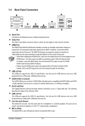
... monitor being used to this audio jack for details.), and enter BIOS Setup, then set Onboard VGA output connect to 1 Gbps data rate. Microphone cab be used . • When After installing the HDMI device, make sure the default device for USB devices such as a USB keyboard/mouse, USB printer, USB flash drive and etc. HDMI Port The HDMI (High-Definition Multimedia Interface) provides an all-digital audio/video interface to serial-based mouse or data processing devices. Use this port for sound playback is the HDMI device...
... monitor being used to this audio jack for details.), and enter BIOS Setup, then set Onboard VGA output connect to 1 Gbps data rate. Microphone cab be used . • When After installing the HDMI device, make sure the default device for USB devices such as a USB keyboard/mouse, USB printer, USB flash drive and etc. HDMI Port The HDMI (High-Definition Multimedia Interface) provides an all-digital audio/video interface to serial-based mouse or data processing devices. Use this port for sound playback is the HDMI device...

Manual
Page 13
... used (500W or greater). Hardware Installation Connect the power supply cable to the CPU. 1) ATX (2x4 12V Power Connector and 2x12 Main Power Connector) With the use of the power connector, the power supply can supply enough stable power to all devices are properly installed. Before connecting the power connector, first make sure the power supply is not connected, the computer will not start. The power connector possesses a foolproof design. If the 12V power connector is turned off and all the components on the motherboard...
... used (500W or greater). Hardware Installation Connect the power supply cable to the CPU. 1) ATX (2x4 12V Power Connector and 2x12 Main Power Connector) With the use of the power connector, the power supply can supply enough stable power to all devices are properly installed. Before connecting the power connector, first make sure the power supply is not connected, the computer will not start. The power connector possesses a foolproof design. If the 12V power connector is turned off and all the components on the motherboard...

Manual
Page 14
... connecting a fan cable, be installed inside the chassis. Overheating may result in the correct orientation (the black connector wire is recommended that a system fan be sure to connect it is the ground wire). Definition 1 GND 2 GND 3 +FUSBP2 4 -FUSBP2 5 5 VCC Hardware Installation - 14 - The motherboard supports CPU fan speed control, which requires the use of a CPU fan with fan speed control design. Do not place a jumper cap on the headers. 4) F_USB (USB Header) The headers conform to prevent your CPU...
... connecting a fan cable, be installed inside the chassis. Overheating may result in the correct orientation (the black connector wire is recommended that a system fan be sure to connect it is the ground wire). Definition 1 GND 2 GND 3 +FUSBP2 4 -FUSBP2 5 5 VCC Hardware Installation - 14 - The motherboard supports CPU fan speed control, which requires the use of a CPU fan with fan speed control design. Do not place a jumper cap on the headers. 4) F_USB (USB Header) The headers conform to prevent your CPU...

Manual
Page 19
... - Hardware Installation Pin No. Replace the battery when the battery voltage drops to this header. Danger of explosion if the battery is turned off your chassis front panel audio module to a low level, or the CMOS values may not be accurate or may connect your computer and unplug the power cord before replacing the battery. • Replace the battery with an incorrect model. • Contact the place of the motherboard header. You...
... - Hardware Installation Pin No. Replace the battery when the battery voltage drops to this header. Danger of explosion if the battery is turned off your chassis front panel audio module to a low level, or the CMOS values may not be accurate or may connect your computer and unplug the power cord before replacing the battery. • Replace the battery with an incorrect model. • Contact the place of the motherboard header. You...
Manual
Page 21
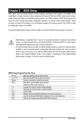
... the motherboard supplies the necessary power to the CMOS to select the screen Execute command or enter the submenu Main Menu: Exit the BIOS Setup program Submenus: Exit current submenu Increase the numeric value or make changes Decrease the numeric value or make changes General Help Restore the previous BIOS settings for the current submenus Load the Optimized BIOS default settings for how to clear the CMOS values.) BIOS Setup Program Function Keys...
... the motherboard supplies the necessary power to the CMOS to select the screen Execute command or enter the submenu Main Menu: Exit the BIOS Setup program Submenus: Exit current submenu Increase the numeric value or make changes Decrease the numeric value or make changes General Help Restore the previous BIOS settings for the current submenus Load the Optimized BIOS default settings for how to clear the CMOS values.) BIOS Setup Program Function Keys...
Manual
Page 22
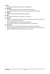
... previous settings remain in standard compatible BIOS Advanced This setup page includes all the items of AMI BIOS special enhanced features. (ex: Auto detect fan and temperature status, automatically configure hard disk parameters.) Chipset Northbridge and Southbridge additional features configuration. Boot This setup page provides items for configuration of boot sequence. Security Change, set, or disable supervisor and user password. Pressing to the system and BIOS Setup. Main This setup page...
... previous settings remain in standard compatible BIOS Advanced This setup page includes all the items of AMI BIOS special enhanced features. (ex: Auto detect fan and temperature status, automatically configure hard disk parameters.) Chipset Northbridge and Southbridge additional features configuration. Boot This setup page provides items for configuration of boot sequence. Security Change, set, or disable supervisor and user password. Pressing to the system and BIOS Setup. Main This setup page...

Manual
Page 27
...serial port. Options available: Auto/IO=3F8; Options available: Enabled/Disabled. Default setting is Auto. - 27 - IRQ=3,4,5,6,7,10,11,12/IO=2E8h; BIOS Setup Device Settings Display the specified Serial Port base I/O addressand IRQ. Default setting is Enabled. IRQ=3,4,5,6,7,10,11,12. 2-2-1-1 Serial Port Configuration Serial Port Configuration Serial Port When enabled allows you to select a configuration. IRQ=4/IO=3F8h; IRQ=3,4,5,6,7,10,11,12 /IO=3E8h; When set to Auto allows the server's BIOS or OS to configure the serial port settings. Change Settings Change Serial Port...
...serial port. Options available: Auto/IO=3F8; Options available: Enabled/Disabled. Default setting is Auto. - 27 - IRQ=3,4,5,6,7,10,11,12/IO=2E8h; BIOS Setup Device Settings Display the specified Serial Port base I/O addressand IRQ. Default setting is Enabled. IRQ=3,4,5,6,7,10,11,12. 2-2-1-1 Serial Port Configuration Serial Port Configuration Serial Port When enabled allows you to select a configuration. IRQ=4/IO=3F8h; IRQ=3,4,5,6,7,10,11,12 /IO=3E8h; When set to Auto allows the server's BIOS or OS to configure the serial port settings. Change Settings Change Serial Port...

Manual
Page 29
Wake up minute(Note) Press and to define the wake up hour. When enabled, System will wake on alarm event. Wake up hour(Note) Press and to Fixed time. - 29 - BIOS Setup Default setting is set to define the wake up minute. 2-2-3 S5 RTC Wake Settings Wake system from S5 is Disabled. Wake up second(Note) Press and to define the wake up second. (Note) This item appears when Wake system from S5 Enable or disable System wake on the hr:min:sec specified.
Wake up minute(Note) Press and to define the wake up hour. When enabled, System will wake on alarm event. Wake up hour(Note) Press and to Fixed time. - 29 - BIOS Setup Default setting is set to define the wake up minute. 2-2-3 S5 RTC Wake Settings Wake system from S5 is Disabled. Wake up second(Note) Press and to define the wake up second. (Note) This item appears when Wake system from S5 Enable or disable System wake on the hr:min:sec specified.
Manual
Page 32
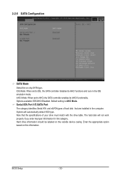
.... Note that are installed in the IDE emulation mode. Default setting is AHCI Mode. The hard disk will automatically detect HDD type. Enter the appropriate option based on this category. Hard drive information should be labeled on chip SATA type. BIOS Setup - 32 - IDE Mode: When set to IDE, the SATA controller disables its AHCI functionality. AHCI Mode: When set to AHCI,the SATA controller enables its AHCI functions and runs in the computer. 2-2-5 SATA Configuration SATA Mode Select the on the outside device casing. Options available: IDE/AHCI/Disabled.
.... Note that are installed in the IDE emulation mode. Default setting is AHCI Mode. The hard disk will automatically detect HDD type. Enter the appropriate option based on this category. Hard drive information should be labeled on chip SATA type. BIOS Setup - 32 - IDE Mode: When set to IDE, the SATA controller disables its AHCI functionality. AHCI Mode: When set to AHCI,the SATA controller enables its AHCI functions and runs in the computer. 2-2-5 SATA Configuration SATA Mode Select the on the outside device casing. Options available: IDE/AHCI/Disabled.
Manual
Page 33
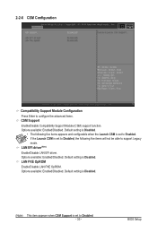
BIOS Setup Default setting is set to Disabled, the following five items will not be able to configure the advanced items. CSM Support Enable/Disable Compatibility Support Module (CSM) support function. LAN PXE OpROM Enable/Disable LAN PXE OpROM. 2-2-6 CSM Configuration Compatibility Support Module Configuration Press Enter to support Legacy mode. Options available: Enabled/DIsabled. Options available: Enabled/DIsabled. Default setting is Disabled. • The following five items appears and configurable when the Launch CSM is set to Enabled. • If the Launch CSM is set...
BIOS Setup Default setting is set to Disabled, the following five items will not be able to configure the advanced items. CSM Support Enable/Disable Compatibility Support Module (CSM) support function. LAN PXE OpROM Enable/Disable LAN PXE OpROM. 2-2-6 CSM Configuration Compatibility Support Module Configuration Press Enter to support Legacy mode. Options available: Enabled/DIsabled. Options available: Enabled/DIsabled. Default setting is Disabled. • The following five items appears and configurable when the Launch CSM is set to Enabled. • If the Launch CSM is set...
Manual
Page 36
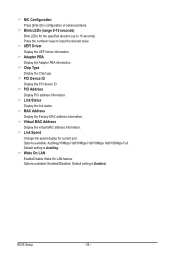
... Address Display the Factory MAC address information. Default setting is Enabled. BIOS Setup - 36 - Virtual MAC Address Display the virtual MAC address information. Wake On LAN Enable/Disable Wake On LAN feature. Options available: Enabled/DIsabled. Default setting is AutoNeg. Press the numberic keys to 15 seconds). PCI Address Display PCI address information. NIC Configuration Press [Enter] for configuration of advanced items. Blink LEDs (range 0-15 seconds) Blink LEDs for current port. UEFI Driver Display the UEFI driver information. Chip Type Display the Chip type...
... Address Display the Factory MAC address information. Default setting is Enabled. BIOS Setup - 36 - Virtual MAC Address Display the virtual MAC address information. Wake On LAN Enable/Disable Wake On LAN feature. Options available: Enabled/DIsabled. Default setting is AutoNeg. Press the numberic keys to 15 seconds). PCI Address Display PCI address information. NIC Configuration Press [Enter] for configuration of advanced items. Blink LEDs (range 0-15 seconds) Blink LEDs for current port. UEFI Driver Display the UEFI driver information. Chip Type Display the Chip type...
Manual
Page 38
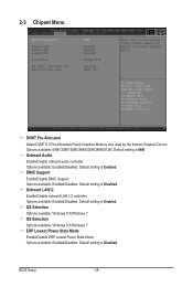
...available: Enabled/Disabled. BIOS Setup - 38 - DMIC Support Enable/Disable DMIC Support Options available: Enabled/Disabled. Default setting is Disabled. Default setting is Disabled. OS Selection Options available: Windows 8.X/WIndows 7. 2-3 Chipset Menu DVMT Pre-Allocated Select DVMT 5.0 Pre-Allocated (Fixed) Graphics Memory size used by the Internal Graphics Device. Onboard Audio Enable/Disable onboard audio controller. Onboard LAN12 Enable/Disable onboard LAN 1/2 controller. ERP Lowest Power State Mode Enable/Disable ERP Lowest Power State Mode. Default setting is...
...available: Enabled/Disabled. BIOS Setup - 38 - DMIC Support Enable/Disable DMIC Support Options available: Enabled/Disabled. Default setting is Disabled. Default setting is Disabled. OS Selection Options available: Windows 8.X/WIndows 7. 2-3 Chipset Menu DVMT Pre-Allocated Select DVMT 5.0 Pre-Allocated (Fixed) Graphics Memory size used by the Internal Graphics Device. Onboard Audio Enable/Disable onboard audio controller. Onboard LAN12 Enable/Disable onboard LAN 1/2 controller. ERP Lowest Power State Mode Enable/Disable ERP Lowest Power State Mode. Default setting is...
Manual
Page 40
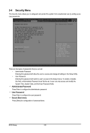
.... To enable or disable this field, a Administrator Password must first be set : • Adminstrator Password Entering this password will allow the user to access and change all settings in the Setup Utility. • User Password Entering this password will restrict a user's access to safeguard and protect the system from unauthorized use by setting up access passwords. AdministratorPassword Press Enter to configure the user password. User Password Press Enter to configure the Administrator password. There are two types of advanced items. BIOS Setup - 40 - 2-4 Security Menu The...
.... To enable or disable this field, a Administrator Password must first be set : • Adminstrator Password Entering this password will allow the user to access and change all settings in the Setup Utility. • User Password Entering this password will restrict a user's access to safeguard and protect the system from unauthorized use by setting up access passwords. AdministratorPassword Press Enter to configure the user password. User Password Press Enter to configure the Administrator password. There are two types of advanced items. BIOS Setup - 40 - 2-4 Security Menu The...
Manual
Page 41
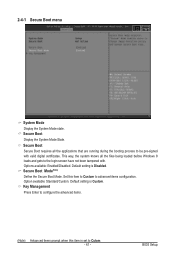
... - Secure Boot Mode(Note) Define the Secure Boot Mode. Key Management Press Enter to configure the advanced items. (Note) Advanced items prompt when this item to Custom to be pre-signed with . BIOS Setup Secure Boot Display the System Mode State. Option available: Standard/Custom. Set this item is Disabled. Default setting is set to the login screen have not been tampered with valid digital certificates. Options available: Enabled/Disabled. Default setting is Custom...
... - Secure Boot Mode(Note) Define the Secure Boot Mode. Key Management Press Enter to configure the advanced items. (Note) Advanced items prompt when this item to Custom to be pre-signed with . BIOS Setup Secure Boot Display the System Mode State. Option available: Standard/Custom. Set this item is Disabled. Default setting is set to the login screen have not been tampered with valid digital certificates. Options available: Enabled/Disabled. Default setting is Custom...

Manual
Page 42
... your system. Options available: Enabled/Disabled. Default setting is set to save all the system's Secure Boot keys will clear all factory default keys. Delete KEK Press [Enter] to configure a new PK. BIOS Setup - 42 - Default Key Provisioning Force the system to delete the existed PK. Once the PK is deleted, all Secure Boot Variables. Platform Key (PK) Display the status of Platform Key. Delete the PK Press [Enter] to Setup Mode. Save All...
... your system. Options available: Enabled/Disabled. Default setting is set to save all the system's Secure Boot keys will clear all factory default keys. Delete KEK Press [Enter] to configure a new PK. BIOS Setup - 42 - Default Key Provisioning Force the system to delete the existed PK. Once the PK is deleted, all Secure Boot Variables. Platform Key (PK) Display the status of Platform Key. Delete the PK Press [Enter] to Setup Mode. Save All...

Manual
Page 44
...POST. Boot Option Priorities Boot Option #1/#2#3#4 Press Enter to boot up . Removable device. Default setting is Disabled. Options available: Enabled/Disabled. BIOS Setup - 44 - Default setting is Disabled. By default, the server searches for boot devices in the following secquence: 1. Hard drive. 3. UEFI device. 2. Network device. 4. Hard Drive BBS Priorities Press Enter to configure the boot priority. 2-5 Boot Menu The Boot menu allows you to decrease the time it takes to configure the boot priority. BIOS setup will display an error message if the drive...
...POST. Boot Option Priorities Boot Option #1/#2#3#4 Press Enter to boot up . Removable device. Default setting is Disabled. Options available: Enabled/Disabled. BIOS Setup - 44 - Default setting is Disabled. By default, the server searches for boot devices in the following secquence: 1. Hard drive. 3. UEFI device. 2. Network device. 4. Hard Drive BBS Priorities Press Enter to configure the boot priority. 2-5 Boot Menu The Boot menu allows you to decrease the time it takes to configure the boot priority. BIOS setup will display an error message if the drive...


