Manual
Page 2
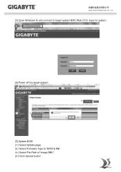
GIGA -BYTE TECHNOLOGY CO., LTD. [3] Open Windows IE and connect to target system BMC Web UI for logon to system. [4] Power off the target system [5] Update BIOS (1.) Select Update page (2.) Select Firmware Type to "BIOS & ME" (3.) Select File Path of "image.RBU" (4.) Click Upload button
GIGA -BYTE TECHNOLOGY CO., LTD. [3] Open Windows IE and connect to target system BMC Web UI for logon to system. [4] Power off the target system [5] Update BIOS (1.) Select Update page (2.) Select Firmware Type to "BIOS & ME" (3.) Select File Path of "image.RBU" (4.) Click Upload button

Manual
Page 6
Update BIOS through free download). [5] Setup TFTP server for Windows client PC (e.g. Preparation [1] Get BIOS image file "image.RBU" of target system. [2] Make sure target system BMC is live. [3] Get BMC IP address of target system. [4] Download TFTP service application for Linux client PC (Please users set up their own TFTP server.). [6] Get ipmitool. 2.2. GIGA -BYTE TECHNOLOGY CO., LTD. 2. BMC command format table Tftpd64.exe/Tftpd32.exe through BMC Command-line interface 2.1.
Update BIOS through free download). [5] Setup TFTP server for Windows client PC (e.g. Preparation [1] Get BIOS image file "image.RBU" of target system. [2] Make sure target system BMC is live. [3] Get BMC IP address of target system. [4] Download TFTP service application for Linux client PC (Please users set up their own TFTP server.). [6] Get ipmitool. 2.2. GIGA -BYTE TECHNOLOGY CO., LTD. 2. BMC command format table Tftpd64.exe/Tftpd32.exe through BMC Command-line interface 2.1.
Manual
Page 8
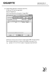
2.3. Update BIOS (Sample on Windows client PC) [1] Set up TFTP service application Execute Tftpd64.exe Set Current Directory to file path of "image.RBU" GIGA -BYTE TECHNOLOGY CO., LTD. [2] Execute cmd.exe and connect to check connect BMC is success or not. ipmitool -H 10.1.27.150 -U admin -P password raw 0x06 0x01 e.g. Use command 0x06 0x01 to target system BMC through ipmitool.
2.3. Update BIOS (Sample on Windows client PC) [1] Set up TFTP service application Execute Tftpd64.exe Set Current Directory to file path of "image.RBU" GIGA -BYTE TECHNOLOGY CO., LTD. [2] Execute cmd.exe and connect to check connect BMC is success or not. ipmitool -H 10.1.27.150 -U admin -P password raw 0x06 0x01 e.g. Use command 0x06 0x01 to target system BMC through ipmitool.
Manual
Page 10
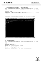
GIGA -BYTE TECHNOLOGY CO., LTD. [4] Upload "image.RBU" through TFTP service application. ipmitool -H 10.1.27.150 -U admin -P password raw 0x2e 0x20 0x0a 0x3c 0x00 0x0e 0x00 0x00 0x0a 0x01 0x1b 0x34 0x69 0x6d 0x61 0x67 0x65 0x2e 0x52 0x42 0x55 Command format: raw...0x65 0x2e 0x52 0x42 0x55 = image.RBU [5] Check upload status e.g. ipmitool -H 10.1.27.150 -U admin -P password raw 0x2e 0x21 0x0a 0x3c 0x00 0x0e Response: 0a 3c 00 01 00 Byte 1 = 00h : Command Completed Normally Byte 2 = 01h : Copying To Scratch Byte 3 = 00h : Update Progress (If byte 2 is 06, this data is available.) e.g.
GIGA -BYTE TECHNOLOGY CO., LTD. [4] Upload "image.RBU" through TFTP service application. ipmitool -H 10.1.27.150 -U admin -P password raw 0x2e 0x20 0x0a 0x3c 0x00 0x0e 0x00 0x00 0x0a 0x01 0x1b 0x34 0x69 0x6d 0x61 0x67 0x65 0x2e 0x52 0x42 0x55 Command format: raw...0x65 0x2e 0x52 0x42 0x55 = image.RBU [5] Check upload status e.g. ipmitool -H 10.1.27.150 -U admin -P password raw 0x2e 0x21 0x0a 0x3c 0x00 0x0e Response: 0a 3c 00 01 00 Byte 1 = 00h : Command Completed Normally Byte 2 = 01h : Copying To Scratch Byte 3 = 00h : Update Progress (If byte 2 is 06, this data is available.) e.g.

Manual
Page 2
... 4 Software Install ...5 Prerequisites on remote management PC 5 Install Java Tool ...5 Gigabyte Content Management Network Configuration 6 Using the Web UI...8 Gigabyte Content Management System Console Overview 9 Enter Gigabyte Content Management System Console 10 Properties ...10 Configuration ...11 Network...11 Network Security ...12 Security ...13 Users ...14 Services ...15 IPMI ...16 Time Setting ...18 Language ...19 Sessions ...20 LDAP ...21 Updates ...22 Utilities ...23 Server Information ...24 General Setting...24 Power Control ...25 Power...
... 4 Software Install ...5 Prerequisites on remote management PC 5 Install Java Tool ...5 Gigabyte Content Management Network Configuration 6 Using the Web UI...8 Gigabyte Content Management System Console Overview 9 Enter Gigabyte Content Management System Console 10 Properties ...10 Configuration ...11 Network...11 Network Security ...12 Security ...13 Users ...14 Services ...15 IPMI ...16 Time Setting ...18 Language ...19 Sessions ...20 LDAP ...21 Updates ...22 Utilities ...23 Server Information ...24 General Setting...24 Power Control ...25 Power...

Manual
Page 5
... LAN. FRU information report includes main board part number, product name, and manufacturer, etc.) Health status/Hardware monitoring report. Events log, view, and clear. Event notification via PET (Platform Event Trap). Platform Event Filtering (PEF) to take selected action for selected events. Chassis management includes power control and status report, front panel buttons and LEDs control. Support...
... LAN. FRU information report includes main board part number, product name, and manufacturer, etc.) Health status/Hardware monitoring report. Events log, view, and clear. Event notification via PET (Platform Event Trap). Platform Event Filtering (PEF) to take selected action for selected events. Chassis management includes power control and status report, front panel buttons and LEDs control. Support...

Manual
Page 6
... home page. 3. Click Download on your system for the following required configuration requirements: Supported Browsers: Internet Explorer 8~12 Google chrome Version 29.0.1547.66m Firefox 2.0 JAVA Recommended Version 8 Update 25 or later version (file size: ~ 623KB) Install Java Tool Please follow the instruction to http://www.java.com 2. Choose the folder location. (Save the file to replace. 9. Click see...
... home page. 3. Click Download on your system for the following required configuration requirements: Supported Browsers: Internet Explorer 8~12 Google chrome Version 29.0.1547.66m Firefox 2.0 JAVA Recommended Version 8 Update 25 or later version (file size: ~ 623KB) Install Java Tool Please follow the instruction to http://www.java.com 2. Choose the folder location. (Save the file to replace. 9. Click see...

Manual
Page 7
Select BMC network Configuration 4. Select Server Management. 3. Define Configuration Address source to BIOS setup menu. 2. Save and Exit. 6. The BMC IP Address will appear on the IPv4 Address parameter. 6 Go to DynamicBmcDhcp or Static. 5. Gigabyte Content Management Network Configuration Please follow the instruction to enable the console redirection function. 1.
Select BMC network Configuration 4. Select Server Management. 3. Define Configuration Address source to BIOS setup menu. 2. Save and Exit. 6. The BMC IP Address will appear on the IPv4 Address parameter. 6 Go to DynamicBmcDhcp or Static. 5. Gigabyte Content Management Network Configuration Please follow the instruction to enable the console redirection function. 1.
Manual
Page 10
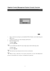
... IP address can be found using the root user name and password, you log in lower-case characters. Gigabyte Content Management System Console Overview 1. Enter the following values: Username: root Password: superuser The default user name and password are in using your identified IP. It is Intel C20x series chipset, please enter the following values: Username: admin Password: password If your motherboard is advised that once you...
... IP address can be found using the root user name and password, you log in lower-case characters. Gigabyte Content Management System Console Overview 1. Enter the following values: Username: root Password: superuser The default user name and password are in using your identified IP. It is Intel C20x series chipset, please enter the following values: Username: admin Password: password If your motherboard is advised that once you...
Manual
Page 17
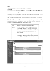
... execute configuration commands that would disable the channel that can be considered the lowest privilege level. With Channel Privilege Level Limit, users can change user access privileges. The following table shows the Channel Privilege Level. The Connection Mode Settings allows user to select the Console redirection type and to be executed. IPMI Serial There are allowed to manage the system from the drop-down list. Administrator...
... execute configuration commands that would disable the channel that can be considered the lowest privilege level. With Channel Privilege Level Limit, users can change user access privileges. The following table shows the Channel Privilege Level. The Connection Mode Settings allows user to select the Console redirection type and to be executed. IPMI Serial There are allowed to manage the system from the drop-down list. Administrator...

Manual
Page 18
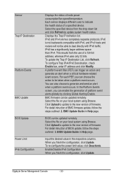
When you finish the configuration, click "Apply Changes". 17 To activate IPMI remote configuration by LAN, check Enable IPMI Over LAN option, define the Channel Privilege Level Limit, and enter the Encryption Key. IPMI Settings IPMI Settings provides remote configuration over LAN.
When you finish the configuration, click "Apply Changes". 17 To activate IPMI remote configuration by LAN, check Enable IPMI Over LAN option, define the Channel Privilege Level Limit, and enter the Encryption Key. IPMI Settings IPMI Settings provides remote configuration over LAN.
Manual
Page 19
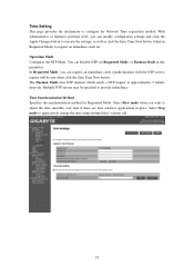
... Apply Changes button to adjust the time smoothly over time if there are time sensitive applications in place. The Daemon Mode runs NTP daemon which sends a NTP request at approximately 5 minute intervals. Operation Mode Configures the NTP Mode. You can request an immediate clock synchronization with the NTP server; Select Slew mode when you can Disable NTP, set . Time Setting This...
... Apply Changes button to adjust the time smoothly over time if there are time sensitive applications in place. The Daemon Mode runs NTP daemon which sends a NTP request at approximately 5 minute intervals. Operation Mode Configures the NTP Mode. You can request an immediate clock synchronization with the NTP server; Select Slew mode when you can Disable NTP, set . Time Setting This...

Manual
Page 25
Define Auto Refresh Interval and Sensor Type form the drop-down list, and select Display Type. Click Refresh to update current health status for Voltage, Power Supplies, Fans and Temperatures. 24 Server Information General Setting This page displays a real-time record of the system health related information such as Voltage, Power Supplies, Fans and Temperatures.
Define Auto Refresh Interval and Sensor Type form the drop-down list, and select Display Type. Click Refresh to update current health status for Voltage, Power Supplies, Fans and Temperatures. 24 Server Information General Setting This page displays a real-time record of the system health related information such as Voltage, Power Supplies, Fans and Temperatures.
Manual
Page 3
... 1-5-4 pgadminIII Installation Procedure (Optional 15 1-5-5 Login Gigabyte Server Management Console 16 Chapter 2 Gigabyte Server Management Console 17 2-1 Overview...17 2-2 Enter Gigabyte Server Management Console 18 2-2-1 Node Info...18 2-2-1-1 Node ID...20 Power Consumption...20 SEL ...21 Node Detail...21 Chassis ...22 Sensor ...23 Trap IP Destination List...24 Platform Events...25 BMC Update...26 BIOS Update...26 Power Limit...27 IP Configuration...27 CPU Utilization...27...
... 1-5-4 pgadminIII Installation Procedure (Optional 15 1-5-5 Login Gigabyte Server Management Console 16 Chapter 2 Gigabyte Server Management Console 17 2-1 Overview...17 2-2 Enter Gigabyte Server Management Console 18 2-2-1 Node Info...18 2-2-1-1 Node ID...20 Power Consumption...20 SEL ...21 Node Detail...21 Chassis ...22 Sensor ...23 Trap IP Destination List...24 Platform Events...25 BMC Update...26 BIOS Update...26 Power Limit...27 IP Configuration...27 CPU Utilization...27...

Manual
Page 5
... required configuration requirements: • System Processor: 2 GHz and above • System Memory: Minimum 4 GB RAM • Free Disk Space: 1000 GB at least • Node servers : 255 maximum 1-3 Software Requirement 1-3-1 Prerequisites on remote management server Supported Browsers: • Internet Explorer 9 or later • Google Chrome 39.0.2171.65 m or later • Mozilla Firefox 33.1.1 Operating System: • Windows 2008...
... required configuration requirements: • System Processor: 2 GHz and above • System Memory: Minimum 4 GB RAM • Free Disk Space: 1000 GB at least • Node servers : 255 maximum 1-3 Software Requirement 1-3-1 Prerequisites on remote management server Supported Browsers: • Internet Explorer 9 or later • Google Chrome 39.0.2171.65 m or later • Mozilla Firefox 33.1.1 Operating System: • Windows 2008...

Manual
Page 16
... localhost 2. Enter Database User Name postgres • This utility supported CentOS 6.3 or later version. • PostgreSQL must be execute in root authority. • In Fedora 19, you have to install package in the following: Locate and edit your distributions .repo file, located: vi /etc/yum.repos.d/fedora.repo and /etc/yum.repos.d/fedora-updates.repo ([fedora] sections) Install PGDG RPM file: curl...
... localhost 2. Enter Database User Name postgres • This utility supported CentOS 6.3 or later version. • PostgreSQL must be execute in root authority. • In Fedora 19, you have to install package in the following: Locate and edit your distributions .repo file, located: vi /etc/yum.repos.d/fedora.repo and /etc/yum.repos.d/fedora-updates.repo ([fedora] sections) Install PGDG RPM file: curl...
Manual
Page 31
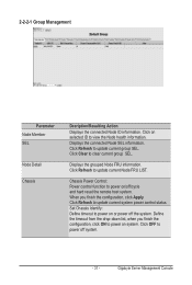
... update current system power control status. Gigabyte Server Management Console Click Refresh to clear current group SEL. Chassis Power Control: Power control function to view the Node health information. 2-2-2-1 Group Management Parameter Node Member SEL Node Detail Chassis Decription/Resulting Action Displays the connected Node ID information. When you finish the configuration, click ON to power on selected ID to power on or power off /cycle and hard reset...
... update current system power control status. Gigabyte Server Management Console Click Refresh to clear current group SEL. Chassis Power Control: Power control function to view the Node health information. 2-2-2-1 Group Management Parameter Node Member SEL Node Detail Chassis Decription/Resulting Action Displays the connected Node ID information. When you finish the configuration, click ON to power on selected ID to power on or power off /cycle and hard reset...
Manual
Page 32
... status of node power consumption/fan speed/temperature. For each PEF, you can choose the action to be able to the new version of firmware. Click Upload to update to the new version of firmware. Gigabyte Server Management Console - 32 - IPv6 has a significantly larger address space than IPv4. In the Platform Events screen, you can enable the generation of BIOS update, follow the steps...
... status of node power consumption/fan speed/temperature. For each PEF, you can choose the action to be able to the new version of firmware. Click Upload to update to the new version of firmware. Gigabyte Server Management Console - 32 - IPv6 has a significantly larger address space than IPv4. In the Platform Events screen, you can enable the generation of BIOS update, follow the steps...
Manual
Page 38
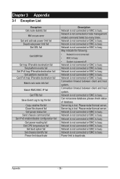
... fail Match rack node info fail Match RMC/BMC IP fail Get FRU fail Save Event Log to log file fail Copy catalina file fail Close file channel fail Get power status fail Send chassis command fail Set IPv6 enable/disable configuration fail Get power reading fail Get CPU temperature fail Set boot option fail Set chassis identify fail Power limit deactivate Description Network is not connected or BMC is lost .
... fail Match rack node info fail Match RMC/BMC IP fail Get FRU fail Save Event Log to log file fail Copy catalina file fail Close file channel fail Get power status fail Send chassis command fail Set IPv6 enable/disable configuration fail Get power reading fail Get CPU temperature fail Set boot option fail Set chassis identify fail Power limit deactivate Description Network is not connected or BMC is lost .
Manual
Page 1
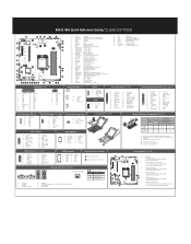
... Supervisor Password Jumper 1-2 Close: Normal operation. (Default setting) 2-3 Close: Skip supervisor password. 3 BIOS Recovery Jumper 1-2 Close: Normal operation. (Default setting) 2-3 Close: BIOS recovery mode. 4 4 35 ME Recovery Jumper 1-2 Close: Normal operation. (Default setting) 2-3 Close: ME recovery mode. Code Description 36 TPM TPM module connector 37 BP_1 HDD back plane board header 38 COM2 Serial port cable connector 39 PCIE_1 PCI Express x8 slot 40 PCIE_2 PCI Express x16 slot 41 ME_UPDATE ME update jumper 42 S3_MASK S3 Power On Select jumper 24 12 No. Pin De...
... Supervisor Password Jumper 1-2 Close: Normal operation. (Default setting) 2-3 Close: Skip supervisor password. 3 BIOS Recovery Jumper 1-2 Close: Normal operation. (Default setting) 2-3 Close: BIOS recovery mode. 4 4 35 ME Recovery Jumper 1-2 Close: Normal operation. (Default setting) 2-3 Close: ME recovery mode. Code Description 36 TPM TPM module connector 37 BP_1 HDD back plane board header 38 COM2 Serial port cable connector 39 PCIE_1 PCI Express x8 slot 40 PCIE_2 PCI Express x16 slot 41 ME_UPDATE ME update jumper 42 S3_MASK S3 Power On Select jumper 24 12 No. Pin De...


