
Manual
Page 3
......4 MSH87DI-SI Motherboard Layout 5 Chapter 1 Hardware Installation 8 1-1 Installation Precautions 8 1-2 Product Specifications 9 1-3 Installing the CPU and CPU Cooler 11 1-3-1 Installing the CPU...11 1-3-2 Installing the CPU Cooler 13 1-4 Installing the Memory 14 1-4-1 Dual Channel Memory Configuration 14 1-4-2 Installing a Memory 15 1-5 Back Panel Connectors 16 1-6 Internal Connectors 18 Chapter 2 BIOS Setup 30 2-1 The Main Menu 32 2-2 Advanced Menu 34 2-2-1 CPU Configuration 35 2-2-2 SATA Configuration 37 2-2-3 Intel (R) Rapid Start Technology 38 2-2-4 H/W Monitor...39...
......4 MSH87DI-SI Motherboard Layout 5 Chapter 1 Hardware Installation 8 1-1 Installation Precautions 8 1-2 Product Specifications 9 1-3 Installing the CPU and CPU Cooler 11 1-3-1 Installing the CPU...11 1-3-2 Installing the CPU Cooler 13 1-4 Installing the Memory 14 1-4-1 Dual Channel Memory Configuration 14 1-4-2 Installing a Memory 15 1-5 Back Panel Connectors 16 1-6 Internal Connectors 18 Chapter 2 BIOS Setup 30 2-1 The Main Menu 32 2-2 Advanced Menu 34 2-2-1 CPU Configuration 35 2-2-2 SATA Configuration 37 2-2-3 Intel (R) Rapid Start Technology 38 2-2-4 H/W Monitor...39...
Manual
Page 6
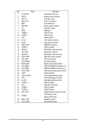
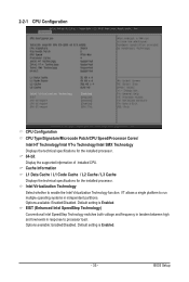
... In power connector 2 pin power connector WEBCAM connector USB 3.0 header SATA 6Gb/s cable connector System fan connector SATA 6Gb/s cable connector Hard disk power connector CPU fan connector Front panel header Monitor power switch header DDR3 SO-DIMM slot (channel 2-1 ) DDR3 SO-DIMM slot (channel 1-1 ) LVDS power select jumper (3V/5V) LVDS connector LVDS Eeable/Disable jumper Flat Panel Display connector Back light brightness switch USB 2.0 header Intel LGA1155 socket USB 2.0 header USB 2.0 header mSATA/extension board connector PCI Express x4 slot (Support 25W Only) Digital Mic header Clear...
... In power connector 2 pin power connector WEBCAM connector USB 3.0 header SATA 6Gb/s cable connector System fan connector SATA 6Gb/s cable connector Hard disk power connector CPU fan connector Front panel header Monitor power switch header DDR3 SO-DIMM slot (channel 2-1 ) DDR3 SO-DIMM slot (channel 1-1 ) LVDS power select jumper (3V/5V) LVDS connector LVDS Eeable/Disable jumper Flat Panel Display connector Back light brightness switch USB 2.0 header Intel LGA1155 socket USB 2.0 header USB 2.0 header mSATA/extension board connector PCI Express x4 slot (Support 25W Only) Digital Mic header Clear...

Manual
Page 7
... unplugging the power supply cable from the power outlet before installing or removing the motherboard or other hardware components. • When connecting hardware components to the internal connectors on the computer power during the installation process can become damaged as a motherboard, CPU or memory. If you are uncertain about any installation steps or have it on top of an antistatic pad or within the computer casing. •...
... unplugging the power supply cable from the power outlet before installing or removing the motherboard or other hardware components. • When connecting hardware components to the internal connectors on the computer power during the installation process can become damaged as a motherboard, CPU or memory. If you are uncertain about any installation steps or have it on top of an antistatic pad or within the computer casing. •...
Manual
Page 8
... slot (Max. 1-2 Product Specifications CPU Chipset Memory Display Audio LAN ŠŠ Support for Intel® Core™ i7, Core™i5, Core™i3 processors/Intel® Pentium® processors in Intel® processor 2 x SATA 6Gb/s connectors USB ŠŠ 4 x USB 3.0 ports (back panel) ŠŠ 3 x USB 2.0 headers (Card reader/Touch panel/and other devices) Internal Connectors ŠŠ 1 x 2-pin power connector ŠŠ 2 x SATA 6Gb/s connectors ŠŠ 1 x SATA HDD power connector ŠŠ 1 x CPU fan header ŠŠ 1 x System fan header...
... slot (Max. 1-2 Product Specifications CPU Chipset Memory Display Audio LAN ŠŠ Support for Intel® Core™ i7, Core™i5, Core™i3 processors/Intel® Pentium® processors in Intel® processor 2 x SATA 6Gb/s connectors USB ŠŠ 4 x USB 3.0 ports (back panel) ŠŠ 3 x USB 2.0 headers (Card reader/Touch panel/and other devices) Internal Connectors ŠŠ 1 x 2-pin power connector ŠŠ 2 x SATA 6Gb/s connectors ŠŠ 1 x SATA HDD power connector ŠŠ 1 x CPU fan header ŠŠ 1 x System fan header...

Manual
Page 10
... that the motherboard supports the CPU. • Always turn off the computer and unplug the power cord from the power outlet before you begin to install the CPU: • Make sure that the system bus frequency be inserted if oriented incorrectly. (Or you wish to set beyond the standard specifications, please do so according to your hardware specifications including the CPU, graphics card, memory, hard drive, etc. 1-3-1 Installing the CPU A. Hardware Installation
... that the motherboard supports the CPU. • Always turn off the computer and unplug the power cord from the power outlet before you begin to install the CPU: • Make sure that the system bus frequency be inserted if oriented incorrectly. (Or you wish to set beyond the standard specifications, please do so according to your hardware specifications including the CPU, graphics card, memory, hard drive, etc. 1-3-1 Installing the CPU A. Hardware Installation

Manual
Page 13
... that the motherboard supports the memory. SO_DIMM1 SO_DIMM2 Due to prevent hardware damage. • Memory modules have a foolproof design. For Dual-channel operation, DIMMs must be enabled if only one direction. Enabling Dual Channel memory mode will automatically detect the specifications and capacity of the same capacity, brand, speed, and chips be used . • Always turn off the computer and unplug the power cord from SO_DIMM2 socket. Hardware Installation - 14...
... that the motherboard supports the memory. SO_DIMM1 SO_DIMM2 Due to prevent hardware damage. • Memory modules have a foolproof design. For Dual-channel operation, DIMMs must be enabled if only one direction. Enabling Dual Channel memory mode will automatically detect the specifications and capacity of the same capacity, brand, speed, and chips be used . • Always turn off the computer and unplug the power cord from SO_DIMM2 socket. Hardware Installation - 14...

Manual
Page 14
Be sure to remove the DIMM module. 1 2 - 15 - Please note that memory module has a foolproof insertion design. Push down the memory and seat it firmly. Step 3. Reverse the installation steps when you wish to install DDR3 DIMMs on this motherboard. 1-4-2 Installing a Memory Before installing a memory module, make sure to turn off the computer and unplug the power cord from the power outlet to prevent...
Be sure to remove the DIMM module. 1 2 - 15 - Please note that memory module has a foolproof insertion design. Push down the memory and seat it firmly. Step 3. Reverse the installation steps when you wish to install DDR3 DIMMs on this motherboard. 1-4-2 Installing a Memory Before installing a memory module, make sure to turn off the computer and unplug the power cord from the power outlet to prevent...

Manual
Page 15
... the LAN port LEDs. Hardware Installation - 16 - HDMI Port The HDMI (High-Definition Multimedia Interface) provides an all-digital audio/video interface to this port for USB devices such as the default play-back device. Connect the HDMI audio/video device to transmit the uncompressed audio/video signals and is HDCP compliant. Refer to MIC In jack. Microphone cab be used . 1-5 Back Panel Connectors DC Power Jack Connect the DC power to Start>Control Panel>Hardware and Sound>Sound>Playback and set Onboard VGA output connect to...
... the LAN port LEDs. Hardware Installation - 16 - HDMI Port The HDMI (High-Definition Multimedia Interface) provides an all-digital audio/video interface to this port for USB devices such as the default play-back device. Connect the HDMI audio/video device to transmit the uncompressed audio/video signals and is HDCP compliant. Refer to MIC In jack. Microphone cab be used . 1-5 Back Panel Connectors DC Power Jack Connect the DC power to Start>Control Panel>Hardware and Sound>Sound>Playback and set Onboard VGA output connect to...

Manual
Page 22
... connector wire is recommended that a system fan be installed inside the chassis. 1 SYS_FAN CPU_FAN Pin No. 1 2 3 4 Definition GND +12V Sense Speed Control • Be sure to connect fan cables to the fan headers to the CPU or the system may result in damage to prevent your CPU and system from overheating. Do not place a jumper cap on the headers. 12) SPKR (Speaker Header) Pin No. The motherboard supports CPU fan speed control, which requires the use of a CPU fan...
... connector wire is recommended that a system fan be installed inside the chassis. 1 SYS_FAN CPU_FAN Pin No. 1 2 3 4 Definition GND +12V Sense Speed Control • Be sure to connect fan cables to the fan headers to the CPU or the system may result in damage to prevent your CPU and system from overheating. Do not place a jumper cap on the headers. 12) SPKR (Speaker Header) Pin No. The motherboard supports CPU fan speed control, which requires the use of a CPU fan...

Manual
Page 23
... Power DMIC DATA GND DMIC CLK No Pin Hardware Installation - 24 - You may connect your chassis front panel audio module to work or even damage it. 9 1 10 2 Pin No. 1 2 3 4 5 6 7 8 9 10 Definition F_MIC_L GND F_MIC_R GPIO_DET F_LINE_R F_MIC_JD GND No Pin F_LINE_L F_LINE_JD • The front panel audio header supports HD audio by default. • Audio signals will make the device unable to this header. 13) FP_AUDIO (Front Panel Audio Header) The front panel audio header supports...
... Power DMIC DATA GND DMIC CLK No Pin Hardware Installation - 24 - You may connect your chassis front panel audio module to work or even damage it. 9 1 10 2 Pin No. 1 2 3 4 5 6 7 8 9 10 Definition F_MIC_L GND F_MIC_R GPIO_DET F_LINE_R F_MIC_JD GND No Pin F_LINE_L F_LINE_JD • The front panel audio header supports HD audio by default. • Audio signals will make the device unable to this header. 13) FP_AUDIO (Front Panel Audio Header) The front panel audio header supports...

Manual
Page 26
...) BATTERY (Battery cable connector) The battery provides power to keep the values (such as BIOS configurations, date, and time information) in accordance with local environmental regulations. 19) CLR_CMOS (Clearing CMOS Jumper) Use this jumper to a low level, or the CMOS values may not be accurate or may cause damage to the motherboard. • After system restart, go to BIOS Setup to load factory defaults (select Restore Defaults) or manually configure the BIOS settings (refer...
...) BATTERY (Battery cable connector) The battery provides power to keep the values (such as BIOS configurations, date, and time information) in accordance with local environmental regulations. 19) CLR_CMOS (Clearing CMOS Jumper) Use this jumper to a low level, or the CMOS values may not be accurate or may cause damage to the motherboard. • After system restart, go to BIOS Setup to load factory defaults (select Restore Defaults) or manually configure the BIOS settings (refer...

Manual
Page 29
... Load the Optimized BIOS default settings for the current submenus Save all the changes and exit the BIOS Setup program BIOS Setup - 30 - To access the BIOS Setup program, press the key during system startup, saving system parameters and loading operating system, etc. To flash the BIOS, do not encounter problems of using the current BIOS version, it with caution. If this occurs, try to clear the CMOS values and reset the board to default...
... Load the Optimized BIOS default settings for the current submenus Save all the changes and exit the BIOS Setup program BIOS Setup - 30 - To access the BIOS Setup program, press the key during system startup, saving system parameters and loading operating system, etc. To flash the BIOS, do not encounter problems of using the current BIOS version, it with caution. If this occurs, try to clear the CMOS values and reset the board to default...
Manual
Page 34
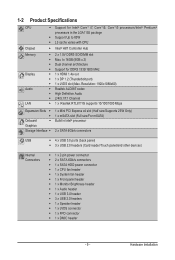
.../Disabled. Default setting is Enabled. EIST (Enhanced Intel SpeedStep Technology) Conventional Intel SpeedStep Technology switches both voltage and frequency in tandem between high and low levels in response to run multiple operating systems in independent partitions. Options available: Enabled/Disabled. BIOS Setup 2-2-1 CPU Configuration CPU Configuration CPU Type/Signature/Microcode Patch/CPU Speed/Processor Cores/ Intel HT Technology/Intel VT-x Technology/Intel SMX Technology Displays the technical specifications for the installed processor. Intel Virtualization Technology...
.../Disabled. Default setting is Enabled. EIST (Enhanced Intel SpeedStep Technology) Conventional Intel SpeedStep Technology switches both voltage and frequency in tandem between high and low levels in response to run multiple operating systems in independent partitions. Options available: Enabled/Disabled. BIOS Setup 2-2-1 CPU Configuration CPU Configuration CPU Type/Signature/Microcode Patch/CPU Speed/Processor Cores/ Intel HT Technology/Intel VT-x Technology/Intel SMX Technology Displays the technical specifications for the installed processor. Intel Virtualization Technology...

Manual
Page 35
... to let the CPU enter C3/C6 mode in system halt state. The C3/C6 state is a more information about Intel CPUs' unique features, please visit Intel's website. Options available: Enabled/Disabled. For more enhanced power-saving state than C1. Default setting is CPU C7s. (Note) This item is Enabled. CPU C7 Report (Note) Allows you install a CPU that supports this feature. BIOS Setup - 36 - CPU C3/C6...
... to let the CPU enter C3/C6 mode in system halt state. The C3/C6 state is a more information about Intel CPUs' unique features, please visit Intel's website. Options available: Enabled/Disabled. For more enhanced power-saving state than C1. Default setting is CPU C7s. (Note) This item is Enabled. CPU C7 Report (Note) Allows you install a CPU that supports this feature. BIOS Setup - 36 - CPU C3/C6...

Manual
Page 36
... detect HDD type. Options available: Enabled/Disabled. Default setting is Disabled. - 37 - Note that the specifications of hard disk that are installed in the IDE emulation mode. Hot Plug (for Serial SATA Port 0/1) Enable/Disable Hot Plug support for this information. BIOS Setup IDE Mode: When set to IDE, the SATA controller disables its AHCI functionality. Default setting is AHCI Mode. Serial ATA Port 0/Serial ATA Port 1/mSATA The category identifies Serial ATA and mSATA types of your drive must match with the drive table. 2-2-2 SATA Configuration SATA Mode Selection...
... detect HDD type. Options available: Enabled/Disabled. Default setting is Disabled. - 37 - Note that the specifications of hard disk that are installed in the IDE emulation mode. Hot Plug (for Serial SATA Port 0/1) Enable/Disable Hot Plug support for this information. BIOS Setup IDE Mode: When set to IDE, the SATA controller disables its AHCI functionality. Default setting is AHCI Mode. Serial ATA Port 0/Serial ATA Port 1/mSATA The category identifies Serial ATA and mSATA types of your drive must match with the drive table. 2-2-2 SATA Configuration SATA Mode Selection...

Manual
Page 40
Default setting is Enabled. AIC Support Option available: Enabled/Disabled. BIOS Setup Security Level Configure the security level. Default setting is Unique ID. Default setting is Enabled. Default setting is 32. Wake From Thunderbolt Devices Option available: Enabled/Disabled. Default setting is Enabled. - 41 - Thunderbolt PCIe Cache-line Size Configure Thunderbolt PCIe Cache-line Size Option available: 0/1/2/4/8/6/32/64/128. Default setting is Disabled. Intel Sample Code Version Display Intel Sample Code version information. Thunderbolt Host Chip Display the ...
Default setting is Enabled. AIC Support Option available: Enabled/Disabled. BIOS Setup Security Level Configure the security level. Default setting is Unique ID. Default setting is Enabled. Default setting is 32. Wake From Thunderbolt Devices Option available: Enabled/Disabled. Default setting is Enabled. - 41 - Thunderbolt PCIe Cache-line Size Configure Thunderbolt PCIe Cache-line Size Option available: 0/1/2/4/8/6/32/64/128. Default setting is Disabled. Intel Sample Code Version Display Intel Sample Code version information. Thunderbolt Host Chip Display the ...
Manual
Page 42
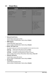
... Device Enable/Disable onboard LAN controller. Default setting is Disabled. - 43 - Erp Support Enable/Disable Erp support function. Options available: Power On/Power Off/Last State. Default setting is Enabled. BIOS Setup Default setting is Disabled. Last State: Set system to set the mode of operation if an AC / power loss occurs. Power Off: Do not power on system when AC power is removed. Options available: Enabled/Disabled. Default setting is re-plugged. DMIC Support Enable/Disable DMIC Support function . 2-3 Chipset Menu Onboard Audio Device Enable/Disable onboard...
... Device Enable/Disable onboard LAN controller. Default setting is Disabled. - 43 - Erp Support Enable/Disable Erp support function. Options available: Power On/Power Off/Last State. Default setting is Enabled. BIOS Setup Default setting is Disabled. Last State: Set system to set the mode of operation if an AC / power loss occurs. Power Off: Do not power on system when AC power is removed. Options available: Enabled/Disabled. Default setting is re-plugged. DMIC Support Enable/Disable DMIC Support function . 2-3 Chipset Menu Onboard Audio Device Enable/Disable onboard...

Manual
Page 43
... and reset system. 4. System rebooting automatically, and re-enter the BIOS setup screen. 5. Press power button to DOS screen. 7. Default setting is Disabled. XHCI Mode Configure XHCI (USB2.0) Mode. Power on system and boot to power off system. (Do not plug-off the power cable) 6. Using Intel flash tool to Enabled. 3. BIOS Setup - 44 - For detail Intel ME firmware update procedure, please see the following section. 2-3-1 Intel ME Firmware Update Procedure Intel ME Firmware Update Procedure: 1. Options available: Auto/Disabled. Options available: Enabled/Disabled...
... and reset system. 4. System rebooting automatically, and re-enter the BIOS setup screen. 5. Press power button to DOS screen. 7. Default setting is Disabled. XHCI Mode Configure XHCI (USB2.0) Mode. Power on system and boot to power off system. (Do not plug-off the power cable) 6. Using Intel flash tool to Enabled. 3. BIOS Setup - 44 - For detail Intel ME firmware update procedure, please see the following section. 2-3-1 Intel ME Firmware Update Procedure Intel ME Firmware Update Procedure: 1. Options available: Auto/Disabled. Options available: Enabled/Disabled...
Manual
Page 47
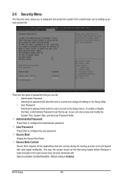
... unauthorized use by setting up access passwords. BIOS Setup - 48 - To enable or disable this password will allow the user to access and change all the files being loaded before Windows 8 loads and gets to the Setup menus. A user can set . Secure Boot Display the Secure Boot State. This way, the system knows all settings in the Setup Utility. • User Password Entering this field, a Administrator Password must first be pre-signed with . Default setting is Enabled. AdministratorPassword Press Enter to configure the user password. 2-5 Security Menu...
... unauthorized use by setting up access passwords. BIOS Setup - 48 - To enable or disable this password will allow the user to access and change all the files being loaded before Windows 8 loads and gets to the Setup menus. A user can set . Secure Boot Display the Secure Boot State. This way, the system knows all settings in the Setup Utility. • User Password Entering this field, a Administrator Password must first be pre-signed with . Default setting is Enabled. AdministratorPassword Press Enter to configure the user password. 2-5 Security Menu...
Manual
Page 49
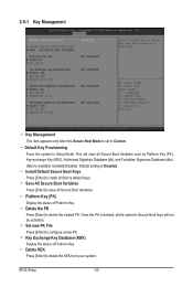
... Boot Variables Press [Enter] to install all Secure Boot Variables such as Platform Key (PK), Key-exchange Key (KEK), Authorized Signature Database (db), and Forbidden Signaures Database (dbx). Set new PK File Press [Enter] to delete the KEK from your system. Platform Key (PK) Display the status of Platform Key. BIOS Setup - 50 - Delete KEK Press [Enter] to configure a new PK. This will not be activated. Options available: Enabled/Disabled. Default Key...
... Boot Variables Press [Enter] to install all Secure Boot Variables such as Platform Key (PK), Key-exchange Key (KEK), Authorized Signature Database (db), and Forbidden Signaures Database (dbx). Set new PK File Press [Enter] to delete the KEK from your system. Platform Key (PK) Display the status of Platform Key. BIOS Setup - 50 - Delete KEK Press [Enter] to configure a new PK. This will not be activated. Options available: Enabled/Disabled. Default Key...


