
Manual
Page 1
MN525RI MN525MI Intel® D525 Processor Motherboards User's Manual Rev. 1001
MN525RI MN525MI Intel® D525 Processor Motherboards User's Manual Rev. 1001

Manual
Page 3
Table of Contents MN525RI Motherboard Layout 4 Chapter 1 Hardware Installation 6 1-1 Installation Precautions 6 1-2 Product Specifications 7 1-3 Installing the Memory 9 1-3-1 Dual Channel Memory Configuration 9 1-3-2 Installing a Memory 10 1-4 Back Panel Connectors 11 1-5 Internal Connectors 12 - 3 -
Table of Contents MN525RI Motherboard Layout 4 Chapter 1 Hardware Installation 6 1-1 Installation Precautions 6 1-2 Product Specifications 7 1-3 Installing the Memory 9 1-3-1 Dual Channel Memory Configuration 9 1-3-2 Installing a Memory 10 1-4 Back Panel Connectors 11 1-5 Internal Connectors 12 - 3 -

Manual
Page 4
MN525RI Motherboard Layout - 4 -
MN525RI Motherboard Layout - 4 -

Manual
Page 6
... the AC power by your hands dry and first touch a metal object to eliminate static electricity. • Prior to installing the motherboard, please have it on top of an antistatic pad or within an electrostatic shielding container. • Before unplugging the power supply cable... from the power outlet before installing or removing the motherboard or other hardware components. • When connecting hardware components to the internal connectors on the computer power during the installation process...
... the AC power by your hands dry and first touch a metal object to eliminate static electricity. • Prior to installing the motherboard, please have it on top of an antistatic pad or within an electrostatic shielding container. • Before unplugging the power supply cable... from the power outlet before installing or removing the motherboard or other hardware components. • When connecting hardware components to the internal connectors on the computer power during the installation process...

Manual
Page 9
... the following : Channel A: SODIMMA Channel B: DIMM1B, DIMM2B SODIMMA SODIMMB Hardware Installation - 9 - A memory module can be used. (Go to GIGABYTE's website for the latest supported memory speeds and memory modules.) • Always turn off the computer and unplug the power cord from the power outlet...each channel has two memory sockets as following guidelines before installing the memory to install the memory: • Make sure that the motherboard supports the memory. If you begin to prevent hardware damage. • Memory modules have a foolproof design. The four DDR3 memory...
... the following : Channel A: SODIMMA Channel B: DIMM1B, DIMM2B SODIMMA SODIMMB Hardware Installation - 9 - A memory module can be used. (Go to GIGABYTE's website for the latest supported memory speeds and memory modules.) • Always turn off the computer and unplug the power cord from the power outlet...each channel has two memory sockets as following guidelines before installing the memory to install the memory: • Make sure that the motherboard supports the memory. If you begin to prevent hardware damage. • Memory modules have a foolproof design. The four DDR3 memory...

Manual
Page 10
... a foolproof insertion design. A memory module can be installed In only one direction. Reverse the installation steps when you wish to install DDR3 DIMMs on this motherboard. Be sure to remove the DIMM module. 1 2 Hardware Installation - 10 - Installation Step: Step 1. Push down the memory and seat it firmly. Step 3. 1-3-2 Installing a Memory Before...
... a foolproof insertion design. A memory module can be installed In only one direction. Reverse the installation steps when you wish to install DDR3 DIMMs on this motherboard. Be sure to remove the DIMM module. 1 2 Hardware Installation - 10 - Installation Step: Step 1. Push down the memory and seat it firmly. Step 3. 1-3-2 Installing a Memory Before...

Manual
Page 11
... - USB 2.0/1.1 Port The USB port supports the USB 2.0/1.1 specification. eSTA Port This connector supports SATA 3Gb/s specification. Do not rock it straight out from the motherboard. • When removing the cable, pull it side to side to 1 Gbps data rate. Hardware Installation USB 2.0/1.1 Port The USB port supports the USB 2.0/1.1 specification...
... - USB 2.0/1.1 Port The USB port supports the USB 2.0/1.1 specification. eSTA Port This connector supports SATA 3Gb/s specification. Do not rock it straight out from the motherboard. • When removing the cable, pull it side to side to 1 Gbps data rate. Hardware Installation USB 2.0/1.1 Port The USB port supports the USB 2.0/1.1 specification...
Manual
Page 12
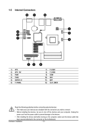
..., make sure your devices are compliant with the connectors you wish to connect. • Before installing the devices, be sure to the connector on the motherboard. Hardware Installation - 12 -
..., make sure your devices are compliant with the connectors you wish to connect. • Before installing the devices, be sure to the connector on the motherboard. Hardware Installation - 12 -

Manual
Page 13
... not connected, the computer will not start. ATX_12V FDD Pin No. If the 12V power connector is turned off and all the components on the motherboard.
... not connected, the computer will not start. ATX_12V FDD Pin No. If the 12V power connector is turned off and all the components on the motherboard.

Manual
Page 14
The motherboard supports CPU fan speed control, which requires the use of a CPU fan with fan speed control design. Definition 1 GND 2 +12V / Speed Control 3 Sense 4 Speed Control &#... Pin No. 1 2 3 4 5 6 7 8 9 10 11 12 - 14 - Most fan headers possess a foolproof insertion design. MSG- ACT+ ACT+ ACT- 2/3) FAN1/FAN2 (CPU Fan/System Fan Headers) The motherboard has a 4-pin CPU fan header (FAN1), a 4-pin (FAN2) system fan headers.
The motherboard supports CPU fan speed control, which requires the use of a CPU fan with fan speed control design. Definition 1 GND 2 +12V / Speed Control 3 Sense 4 Speed Control &#... Pin No. 1 2 3 4 5 6 7 8 9 10 11 12 - 14 - Most fan headers possess a foolproof insertion design. MSG- ACT+ ACT+ ACT- 2/3) FAN1/FAN2 (CPU Fan/System Fan Headers) The motherboard has a 4-pin CPU fan header (FAN1), a 4-pin (FAN2) system fan headers.

Manual
Page 18
... and BIOS configurations) and reset the CMOS values to clear the CMOS values (e.g. Hardware Installation - 18 - Failure to do so may cause damage to the motherboard. • After system restart, go to BIOS Setup to load factory defaults (select Load Optimized Defaults) or manually configure the BIOS settings (refer to Chapter...
... and BIOS configurations) and reset the CMOS values to clear the CMOS values (e.g. Hardware Installation - 18 - Failure to do so may cause damage to the motherboard. • After system restart, go to BIOS Setup to load factory defaults (select Load Optimized Defaults) or manually configure the BIOS settings (refer to Chapter...


