Manual
Page 4
... always ready to give you the support you to get the full benefit of our services, please follow the instructions below carefully. To receive the latest version of our products. So please consult the user's manual first. We are here to help. M10RDI Your satisfaction is a guide to Gigabyte's customer services. In fact, most from Gigabyte's engineers every business day. Please...
... always ready to give you the support you to get the full benefit of our services, please follow the instructions below carefully. To receive the latest version of our products. So please consult the user's manual first. We are here to help. M10RDI Your satisfaction is a guide to Gigabyte's customer services. In fact, most from Gigabyte's engineers every business day. Please...
Manual
Page 5
... apply to use our repair service. Collect all the information about the problem encountered. (For example, CPU type and speed, Gigabyte's products model name, hardware & BIOS revision number, other than repair personnel authorized by Gigabyte, or which have a defective product, follow these steps: 1. A product returned without proof of our customers never need to any of such events. Because of Gigabyte's high quality-control standards and...
... apply to use our repair service. Collect all the information about the problem encountered. (For example, CPU type and speed, Gigabyte's products model name, hardware & BIOS revision number, other than repair personnel authorized by Gigabyte, or which have a defective product, follow these steps: 1. A product returned without proof of our customers never need to any of such events. Because of Gigabyte's high quality-control standards and...
Manual
Page 6
... 31 2.4.14 Front Panel Connector (F_PANEL 31 2.4.15 Front Panel Audio Connector (F_AUDIO 32 2.4.15.1 Signal Description - Ring/+5V/+12V (JCOM3 25 2.4.4 Power Mode Select - Audio connector (F_AUDIO 32 2.4.16 Audio Amplifier Connector (SPK_OUT 33 2.4.17 SATA Power (SATAPW_1 33 2.4.18 SATA Power (SATAPW_2 34 6 M10RDI User's Manual Hardware Configuration 15 2.1 Product Overview ...16 2.2 Before you Proceed 18 2.3 Motherboard Overview 19 2.3.1 Placement Direction ...19 2.3.2 Screw Holes ...19 2.4 Setting Jumpers & Connectors 23 2.4.1 Serial Port Setting - Block Diagram 14 2.
... 31 2.4.14 Front Panel Connector (F_PANEL 31 2.4.15 Front Panel Audio Connector (F_AUDIO 32 2.4.15.1 Signal Description - Ring/+5V/+12V (JCOM3 25 2.4.4 Power Mode Select - Audio connector (F_AUDIO 32 2.4.16 Audio Amplifier Connector (SPK_OUT 33 2.4.17 SATA Power (SATAPW_1 33 2.4.18 SATA Power (SATAPW_2 34 6 M10RDI User's Manual Hardware Configuration 15 2.1 Product Overview ...16 2.2 Before you Proceed 18 2.3 Motherboard Overview 19 2.3.1 Placement Direction ...19 2.3.2 Screw Holes ...19 2.4 Setting Jumpers & Connectors 23 2.4.1 Serial Port Setting - Block Diagram 14 2.
Manual
Page 7
... Low Pin Count Connector (LPC) ...36 3. BIOS Setup ...37 3.1 Introduction ...38 3.2 Starting Setup ...38 3.3 Using Setup ...39 3.4 Getting Help ...40 3.5 In Case of Problems 40 3.6 BIOS setup ...41 3.6.1 Main Menu ...41 3.6.1.1 System Date ...41 3.6.1.2 System Time ...41 3.6.2 Advanced BIOS settings ...42 3.6.2.1 ACPI Settings ...42 3.6.2.2 S5 RTC Wake settings ...43 3.6.2.3 SATA Configuration ...43 3.6.2.3 SATA Configuration ...44 3.6.2.4 USB Configuration ...45 3.6.2.5 F81214 Second Super IO Configuration 46 3.6.2.5.1 Serial Port 1 Configuration 46 3.6.2.5.2 Serial Port 2 Configuration...
... Low Pin Count Connector (LPC) ...36 3. BIOS Setup ...37 3.1 Introduction ...38 3.2 Starting Setup ...38 3.3 Using Setup ...39 3.4 Getting Help ...40 3.5 In Case of Problems 40 3.6 BIOS setup ...41 3.6.1 Main Menu ...41 3.6.1.1 System Date ...41 3.6.1.2 System Time ...41 3.6.2 Advanced BIOS settings ...42 3.6.2.1 ACPI Settings ...42 3.6.2.2 S5 RTC Wake settings ...43 3.6.2.3 SATA Configuration ...43 3.6.2.3 SATA Configuration ...44 3.6.2.4 USB Configuration ...45 3.6.2.5 F81214 Second Super IO Configuration 46 3.6.2.5.1 Serial Port 1 Configuration 46 3.6.2.5.2 Serial Port 2 Configuration...
Manual
Page 9
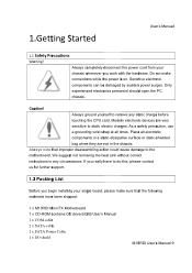
... your single board, please make connections while the power is on. Always note that the following materials have to remove any circumstance. Always ground yourself to do this, please contact us for further support. 1.2 Packing List Before you begin installing your chassis whenever you really have been shipped: 1 x M10RDI Mini-ITX Motherboard 1 x CD-ROM contains OS drivers/QIG/User's Manual 1 x COM cable 2 x SATA cable 2 x SATA Power Cable 1 x I/O shield M10RDI User's Manual 9 1.Getting Started User's Manual 1.1 Safety...
... your single board, please make connections while the power is on. Always note that the following materials have to remove any circumstance. Always ground yourself to do this, please contact us for further support. 1.2 Packing List Before you begin installing your chassis whenever you really have been shipped: 1 x M10RDI Mini-ITX Motherboard 1 x CD-ROM contains OS drivers/QIG/User's Manual 1 x COM cable 2 x SATA cable 2 x SATA Power Cable 1 x I/O shield M10RDI User's Manual 9 1.Getting Started User's Manual 1.1 Safety...
Manual
Page 11
... possible but we would recommend that is available in detail the Gigabyte Technology M10RDI Single Board. We strongly recommend that make booting impossible. If this board. M10RDI User's Manual 11 Whilst all the necessary information is provided in the understanding of this should happen, clear the CMOS settings, (see the description of these, please contact our Customer Service department with M10RDI series or change the standard...
... possible but we would recommend that is available in detail the Gigabyte Technology M10RDI Single Board. We strongly recommend that make booting impossible. If this board. M10RDI User's Manual 11 Whilst all the necessary information is provided in the understanding of this should happen, clear the CMOS settings, (see the description of these, please contact our Customer Service department with M10RDI series or change the standard...
Manual
Page 12
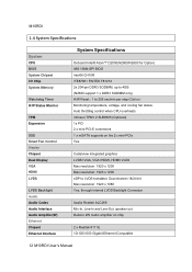
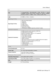
...-PCI-E connectors 1 x mSATA supports on chip 2 x Realtek 8111E 10/100/1000 Gigabit Ethernet Compatible 12 M10RDI User's Manual M10RDI 1.4 System Specifications System CPU BIOS System Chipset I/O Chip System Memory Watchdog Timer H/W Status Monitor TPM Expansion SSD Smart Fan Control Display Chipset Dual Display VGA HDMI LVDS LVDS Backlight Audio Audio Codec Audio Interface Audio Amplifier(W) Ethernet Chipset Ethernet Interface System Specifications Onboard Intel® Atom™ D2550(N2800/N2600 for Option) AMI 16Mb SPI BIOS Intel® ICH10R ITE8783+ FINTEK F81214 2x 204-pin DDR3...
...-PCI-E connectors 1 x mSATA supports on chip 2 x Realtek 8111E 10/100/1000 Gigabit Ethernet Compatible 12 M10RDI User's Manual M10RDI 1.4 System Specifications System CPU BIOS System Chipset I/O Chip System Memory Watchdog Timer H/W Status Monitor TPM Expansion SSD Smart Fan Control Display Chipset Dual Display VGA HDMI LVDS LVDS Backlight Audio Audio Codec Audio Interface Audio Amplifier(W) Ethernet Chipset Ethernet Interface System Specifications Onboard Intel® Atom™ D2550(N2800/N2600 for Option) AMI 16Mb SPI BIOS Intel® ICH10R ITE8783+ FINTEK F81214 2x 204-pin DDR3...
Manual
Page 13
... Audio Connector 1 System Fan Connector 1 GPIO Connector 1 Mini PCI-E Connector full size for mSATA (PCIe1X for Option) 1 Mini PCI-E Connector half size for PCIe slot 1 Speaker-out L/R Connector 1 LVDS Connector 1 LVDS Backlight Connector 1 LPC Connector Power Requirement DC 12V Power Type AT / ATX mode (selectable by jumper, COM4&6, RS-232), 4 SATA II, 1 HDMI, 1 VGA, 1 LVDS, 2 LAN, 1 PS/2 USB 8 USB2.0 ( 4 Rear , 4 internal ) Back Panel I/O Port Back Panel I/O Port Internal I/O Connector Internal I/O Connector Power 1 DC-in Connector (4-pin) 1 VGA Port 1 HDMI Port 2 COM Ports 4 USB...
... Audio Connector 1 System Fan Connector 1 GPIO Connector 1 Mini PCI-E Connector full size for mSATA (PCIe1X for Option) 1 Mini PCI-E Connector half size for PCIe slot 1 Speaker-out L/R Connector 1 LVDS Connector 1 LVDS Backlight Connector 1 LPC Connector Power Requirement DC 12V Power Type AT / ATX mode (selectable by jumper, COM4&6, RS-232), 4 SATA II, 1 HDMI, 1 VGA, 1 LVDS, 2 LAN, 1 PS/2 USB 8 USB2.0 ( 4 Rear , 4 internal ) Back Panel I/O Port Back Panel I/O Port Internal I/O Connector Internal I/O Connector Power 1 DC-in Connector (4-pin) 1 VGA Port 1 HDMI Port 2 COM Ports 4 USB...
Manual
Page 16
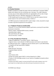
... supports the new revolutionary two-chip layout. VGA - The Intel® Cedarview processor also provides additional flexibility and upgradeability with two slots of SATA, running at 1066 MHz supporting up to 3.0Gb/s • Provides 10/100/1000 Mbps solution to your network or broadband connection without having to buy an • Onboard audio CODEC supports uncompromising DVD audio quality, bringing a move vivid sound experience and high‐quality audio...
... supports the new revolutionary two-chip layout. VGA - The Intel® Cedarview processor also provides additional flexibility and upgradeability with two slots of SATA, running at 1066 MHz supporting up to 3.0Gb/s • Provides 10/100/1000 Mbps solution to your network or broadband connection without having to buy an • Onboard audio CODEC supports uncompromising DVD audio quality, bringing a move vivid sound experience and high‐quality audio...
Manual
Page 18
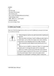
... components. 18 M10RDI User's Manual Unplug the power cord from the power supply. Use a grounded wrist strap or touch a safely grounded object or a metal object, such as the power supply case, before handling components to avoid damaging them . M10RDI • I/O - Before you install motherboard components or change any component, ensure that came with the component. Failure to do so may cause severe damage to 8 ports - Hardware Monitor Fan control (Voltage, Temp...
... components. 18 M10RDI User's Manual Unplug the power cord from the power supply. Use a grounded wrist strap or touch a safely grounded object or a metal object, such as the power supply case, before handling components to avoid damaging them . M10RDI • I/O - Before you install motherboard components or change any component, ensure that came with the component. Failure to do so may cause severe damage to 8 ports - Hardware Monitor Fan control (Voltage, Temp...
Manual
Page 19
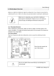
... edge with external ports goes to the rear part of your chassis to ensure that you install the motherboard, study the configuration of the chassis as indicated in the correct orientation. 2.3 Motherboard Overview User's Manual Before you place it . Doing so can cause you physical injury and damage motherboard components. 2.3.1 Placement Direction When installing the motherboard, make sure that the motherboard fits into it...
... edge with external ports goes to the rear part of your chassis to ensure that you install the motherboard, study the configuration of the chassis as indicated in the correct orientation. 2.3 Motherboard Overview User's Manual Before you place it . Doing so can cause you physical injury and damage motherboard components. 2.3.1 Placement Direction When installing the motherboard, make sure that the motherboard fits into it...
Manual
Page 21
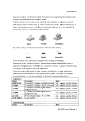
... Serial Port 1 Setting - If you have three pins, labeled 1, 2, and 3. RS232/422/485 Serial Port 1 Select - To "close" a jumper you to configure your system to connect them. In this manual as hard disk drives, a keyboard, or floppy drives. AT or ATX Clear CMOS Note 3 x 1 header, pitch 2.00 mm 3 x 2 header, pitch 2.00 mm 3 x 2 header, pitch 2.54 mm 3 x 2 header, pitch 2.54 mm 3 x 1 header, pitch 2.00 mm 2 x 1 header, pitch 2.54 mm Connectors Labe l Function Note M10RDI User's Manual 21 In addition, the board...
... Serial Port 1 Setting - If you have three pins, labeled 1, 2, and 3. RS232/422/485 Serial Port 1 Select - To "close" a jumper you to configure your system to connect them. In this manual as hard disk drives, a keyboard, or floppy drives. AT or ATX Clear CMOS Note 3 x 1 header, pitch 2.00 mm 3 x 2 header, pitch 2.00 mm 3 x 2 header, pitch 2.54 mm 3 x 2 header, pitch 2.54 mm 3 x 1 header, pitch 2.00 mm 2 x 1 header, pitch 2.54 mm Connectors Labe l Function Note M10RDI User's Manual 21 In addition, the board...
Manual
Page 22
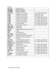
... DC_IN ATX 4pin DC12 DIMM 1 Slot DDR3 DIMM 2 Slot DDR3 System Fan Connector Serial Port 1 Connector Serial Port 2 Connector Serial Port 3 Connector Serial Port 4 Connector Serial Port 5 Connector Serial Port 6 Connector LVDS Connector LCD Inverter Connector USB+LAN1 USB+LAN2 PS/2 Keyboard & Mouse Connector HDMI VGA Connector Mini PCIE Connector 1 Mini PCIE Connector 2 for mSATA AUDIO Line-In/Line-Out/Mic-In PCI Slot Front Panel Audio Connector Audio Amplifier Connector Serial ATA Connector 1/2/3/4 SATA Power 1 SATA Power 2 (Option) USB Connector 1 USB Connector 2 GPIO Connector Low Pin Count...
... DC_IN ATX 4pin DC12 DIMM 1 Slot DDR3 DIMM 2 Slot DDR3 System Fan Connector Serial Port 1 Connector Serial Port 2 Connector Serial Port 3 Connector Serial Port 4 Connector Serial Port 5 Connector Serial Port 6 Connector LVDS Connector LCD Inverter Connector USB+LAN1 USB+LAN2 PS/2 Keyboard & Mouse Connector HDMI VGA Connector Mini PCIE Connector 1 Mini PCIE Connector 2 for mSATA AUDIO Line-In/Line-Out/Mic-In PCI Slot Front Panel Audio Connector Audio Amplifier Connector Serial ATA Connector 1/2/3/4 SATA Power 1 SATA Power 2 (Option) USB Connector 1 USB Connector 2 GPIO Connector Low Pin Count...
Manual
Page 43
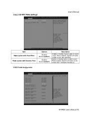
When enabled, System will wake on the current time + Increase minutes (s) 3.6.2.3 SATA Configuration M10RDI User's Manual 43 Enable or disable wake on alarm event. When enabled, System will wake on the hr::min::sec specified. 3.6.2.2 S5 RTC Wake settings User's Manual Item Wake system with Fixed Time Wake system with Dynamic Time Options Enabled Disabled[Default] Enabled Disabled[Default] De scription Enable or disable System wake on alarm event.
When enabled, System will wake on the current time + Increase minutes (s) 3.6.2.3 SATA Configuration M10RDI User's Manual 43 Enable or disable wake on alarm event. When enabled, System will wake on the hr::min::sec specified. 3.6.2.2 S5 RTC Wake settings User's Manual Item Wake system with Fixed Time Wake system with Dynamic Time Options Enabled Disabled[Default] Enabled Disabled[Default] De scription Enable or disable System wake on alarm event.
Manual
Page 44
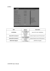
Enable/ Disable Serial ATA Controller 1. Enable/ Disable Serial ATA Controller 0. M10 RDI Item SATA Mode Serial-ATA Controller 0 Serial-ATA Controller 1 eSATA Port Support Options Disabled IDE Mode[Default] ACHI Mode RAID Mode Enabled Disabled Compatible[Default] Enabled[Default] Disabled Enabled Disabled[Default] De scription Select IDE/ AHCI/ RAID Mode. eSATA Port Support. 44 M10RDI User's Manual
Enable/ Disable Serial ATA Controller 1. Enable/ Disable Serial ATA Controller 0. M10 RDI Item SATA Mode Serial-ATA Controller 0 Serial-ATA Controller 1 eSATA Port Support Options Disabled IDE Mode[Default] ACHI Mode RAID Mode Enabled Disabled Compatible[Default] Enabled[Default] Disabled Enabled Disabled[Default] De scription Select IDE/ AHCI/ RAID Mode. eSATA Port Support. 44 M10RDI User's Manual
Manual
Page 45
...ZIP drive). Forced FDD option can be used to boot as floppies. M10RDI User's Manual 45 Mass storage device emulation type. 'AUTO' enumerates devices less than 530MB as FDD (e.g. AUTO option disables legacy support if no USB devices are connected. Item Legacy USB support USB_DRIVE 1.00 Options Enabled[Default] Disabled Auto Auto[Default] Floppy Forced FDD Hard Disk CD‐ROM Descr iption Enables Legacy USB support. User's Manual 3.6.2.4 USB Configuration The USB configuration menu is used to force HDD formatted drive to read USB configuration information and configure USB...
...ZIP drive). Forced FDD option can be used to boot as floppies. M10RDI User's Manual 45 Mass storage device emulation type. 'AUTO' enumerates devices less than 530MB as FDD (e.g. AUTO option disables legacy support if no USB devices are connected. Item Legacy USB support USB_DRIVE 1.00 Options Enabled[Default] Disabled Auto Auto[Default] Floppy Forced FDD Hard Disk CD‐ROM Descr iption Enables Legacy USB support. User's Manual 3.6.2.4 USB Configuration The USB configuration menu is used to force HDD formatted drive to read USB configuration information and configure USB...
Manual
Page 46
Item Serial Port 46 M10RDI User's Manual Options Enabled Disabled[Default] De scription Enable or Disable Serial Port (COM). Set Parameters of Serial Port 1 (COM1). Please refer to set up or change the F81214 Second Super IO configuration for more information. Item Serial Port 1 Configuration Serial Port 2 Configuration 3.6.2.5.1 Serial Port 1 Configuration Description Set Parameters of Serial Port 2 (COM2). M10RDI 3.6.2.5 F81214 Second Super IO Configuration You can use this item to 3.6.2.5.1 and 3.6.2.5.2 for serial ports.
Item Serial Port 46 M10RDI User's Manual Options Enabled Disabled[Default] De scription Enable or Disable Serial Port (COM). Set Parameters of Serial Port 1 (COM1). Please refer to set up or change the F81214 Second Super IO configuration for more information. Item Serial Port 1 Configuration Serial Port 2 Configuration 3.6.2.5.1 Serial Port 1 Configuration Description Set Parameters of Serial Port 2 (COM2). M10RDI 3.6.2.5 F81214 Second Super IO Configuration You can use this item to 3.6.2.5.1 and 3.6.2.5.2 for serial ports.

Manual
Page 52
Enable or Disable the PCI Express Ports in the Chipset. Enable or Disable Boot Option for Legacy Network Devices. Enable or Disable Boot Option for Legacy Network Devices. Enable or Disable the PCI Express Ports in the Chipset. Enable / Disable Azalia HD Audio. Config Intel IGD Settings. 52 M10RDI User's Manual Enable or Disable the PCI Express Ports in the Chipset. Enable or Disable the PCI Express Ports in the Chipset. M10RDI 3.6.3 Advanced Chipset Features Item Restore AC Power Loss Azalia HD Audio Onboard LAN1 LAN PXE ROM Onboard LAN2 LAN PXE ROM Mini PCIE1 Mini ...
Enable or Disable the PCI Express Ports in the Chipset. Enable or Disable Boot Option for Legacy Network Devices. Enable or Disable Boot Option for Legacy Network Devices. Enable or Disable the PCI Express Ports in the Chipset. Enable / Disable Azalia HD Audio. Config Intel IGD Settings. 52 M10RDI User's Manual Enable or Disable the PCI Express Ports in the Chipset. Enable or Disable the PCI Express Ports in the Chipset. M10RDI 3.6.3 Advanced Chipset Features Item Restore AC Power Loss Azalia HD Audio Onboard LAN1 LAN PXE ROM Onboard LAN2 LAN PXE ROM Mini PCIE1 Mini ...
Manual
Page 54
... keyboard NumLock state Quiet Boot Enabled Disabled[Default] Enables or Disables Quiet Boot Option Fast Boot PCI ROM Priority Boot Option #1/2/3 Enabled [Default] Disabled EFI Compatible ROM[Default] Legacy ROM Enables or Disables boot with initialization of a minimal set of devices required to wait for BBS boot options In case of seconds to launch active boot option. M10RDI 3.6.4 Boot settings Item Setup Prompt Timeout Bootup NumLock State Options 1~65535 On [Default] Off De scription Number of multiple Option ROMs(Legacy and EFI Compatible),specifies what PCI Option ROM...
... keyboard NumLock state Quiet Boot Enabled Disabled[Default] Enables or Disables Quiet Boot Option Fast Boot PCI ROM Priority Boot Option #1/2/3 Enabled [Default] Disabled EFI Compatible ROM[Default] Legacy ROM Enables or Disables boot with initialization of a minimal set of devices required to wait for BBS boot options In case of seconds to launch active boot option. M10RDI 3.6.4 Boot settings Item Setup Prompt Timeout Bootup NumLock State Options 1~65535 On [Default] Off De scription Number of multiple Option ROMs(Legacy and EFI Compatible),specifies what PCI Option ROM...
Manual
Page 57
... devices and allows the user to override the Boot Option Priorities list for preserving custom BIOS setup configurations. 3.6.6.9 Restore user defaults This option restores all BIOS settings to the user defaults. If no changes have been changed and saved, a reboot will be valid. This option is useful if the controller exhibits unpredictable behavior due to an incorrect or inappropriate BIOS setting. 3.6.6.8 Save as user defaults This option saves a copy of the current BIOS settings as the User Defaults. If BIOS setup options...
... devices and allows the user to override the Boot Option Priorities list for preserving custom BIOS setup configurations. 3.6.6.9 Restore user defaults This option restores all BIOS settings to the user defaults. If no changes have been changed and saved, a reboot will be valid. This option is useful if the controller exhibits unpredictable behavior due to an incorrect or inappropriate BIOS setting. 3.6.6.8 Save as user defaults This option saves a copy of the current BIOS settings as the User Defaults. If BIOS setup options...


