User Guide
Page 6
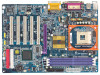
... 5 GA-8PE800(-L) Motherboard Layout 7 Block Diagram 8 Chapter 2 Hardware Installation Process 10 Step 1: Install the Central Processing Unit (CPU 11 Step 1-1: CPU Installation 11 Step 1-2 : CPU Cooling Fan Installation 12 Step 2: Install memory modules 13 Step 3: Install expansion cards 15 Step 4: Connect ribbon cables, cabinet wires, and power supply 16 Step 4-1: I/O Back Panel Introduction 16 Step 4-2: Connectors & Jumper Setting Introduction 18 Chapter 3 BIOS Setup 31 The Main Menu (For example: BIOS Ver. : F7a 32 Standard CMOS Features 34 Advanced BIOS Features 37...
... 5 GA-8PE800(-L) Motherboard Layout 7 Block Diagram 8 Chapter 2 Hardware Installation Process 10 Step 1: Install the Central Processing Unit (CPU 11 Step 1-1: CPU Installation 11 Step 1-2 : CPU Cooling Fan Installation 12 Step 2: Install memory modules 13 Step 3: Install expansion cards 15 Step 4: Connect ribbon cables, cabinet wires, and power supply 16 Step 4-1: I/O Back Panel Introduction 16 Step 4-2: Connectors & Jumper Setting Introduction 18 Chapter 3 BIOS Setup 31 The Main Menu (For example: BIOS Ver. : F7a 32 Standard CMOS Features 34 Advanced BIOS Features 37...
User Guide
Page 8
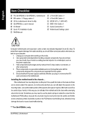
... the motherboard to the chassis... "*" For GA-8PE800-L only. English Item Checklist þ The GA-8PE800 or GA-8PE800-L motherboard þ IDE cable x 1/ Floppy cable x 1 þ CD for motherboard driver & utility þ GA-8PE800(-L) user's manual þ I/O Shield * þ Quick PC Installation Guide o RAID Manual þ 2 Port USB Cable x 1 o 4 Port USB Cable x 1 o SPDIF-KIT x 1 (SPD-KIT) o IEEE 1394 Cable x1 o Audio Combo Kit x 1 þ Motherboard Settings Label Computer motherboards and expansion cards contain very delicate Integrated Circuit (IC) chips. Place...
... the motherboard to the chassis... "*" For GA-8PE800-L only. English Item Checklist þ The GA-8PE800 or GA-8PE800-L motherboard þ IDE cable x 1/ Floppy cable x 1 þ CD for motherboard driver & utility þ GA-8PE800(-L) user's manual þ I/O Shield * þ Quick PC Installation Guide o RAID Manual þ 2 Port USB Cable x 1 o 4 Port USB Cable x 1 o SPDIF-KIT x 1 (SPD-KIT) o IEEE 1394 Cable x1 o Audio Combo Kit x 1 þ Motherboard Settings Label Computer motherboards and expansion cards contain very delicate Integrated Circuit (IC) chips. Place...
User Guide
Page 9
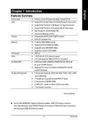
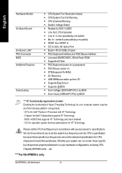
...; 4 processor - ICH4 I /O Control Slots On-Board IDE On-Board Peripherals - Supports up to 2GB DRAM (Max) - Socket 478 for up to 4 ATAPI devices - M Due to be continued...... Support Intel® Pentium® 4 Processor with 360K, 720K,1.2M, 1.44M and 2.88M bytes. - 1 Parallel port supports Normal/EPP/ECP mode - 2 Serial ports (COMA&COMB) - 6 USB 2.0/1.1 ports (2 x Rear, 4 xFront by cable) - 1 FrontAudio Connector to (Intel 845PE/GE) chipset architecture limitation, DDR 333 memory module is only supported when using...
...; 4 processor - ICH4 I /O Control Slots On-Board IDE On-Board Peripherals - Supports up to 2GB DRAM (Max) - Socket 478 for up to 4 ATAPI devices - M Due to be continued...... Support Intel® Pentium® 4 Processor with 360K, 720K,1.2M, 1.44M and 2.88M bytes. - 1 Parallel port supports Normal/EPP/ECP mode - 2 Serial ports (COMA&COMB) - 6 USB 2.0/1.1 ports (2 x Rear, 4 xFront by cable) - 1 FrontAudio Connector to (Intel 845PE/GE) chipset architecture limitation, DDR 333 memory module is only supported when using...
User Guide
Page 10
...(-L) Motherboard - 6 - CD In/ AUX_IN/ Game Port - AC Recovery - Chipset: An Intel® Chipset that supports HT Technology and has it enabled - Whether your hardware configurations, including CPU, Chipsets,SDRAM,Cards... .etc. CPU/System Fan Revolution detect - SPDIF Out /SPDIF In - PS/2 Keyboard interface and PS/2 Mouse interface - PS/2 Keyboard power on - Mic In / center& subwoofer(by s/w switch) - STR(Suspend-To-RAM) - English Hardware Monitor On-Board Sound On-Board LAN * PS/2 Connector BIOS Additional Features Overclocking - CPU Overheat Warning - System Voltage...
...(-L) Motherboard - 6 - CD In/ AUX_IN/ Game Port - AC Recovery - Chipset: An Intel® Chipset that supports HT Technology and has it enabled - Whether your hardware configurations, including CPU, Chipsets,SDRAM,Cards... .etc. CPU/System Fan Revolution detect - SPDIF Out /SPDIF In - PS/2 Keyboard interface and PS/2 Mouse interface - PS/2 Keyboard power on - Mic In / center& subwoofer(by s/w switch) - STR(Suspend-To-RAM) - English Hardware Monitor On-Board Sound On-Board LAN * PS/2 Connector BIOS Additional Features Overclocking - CPU Overheat Warning - System Voltage...
User Guide
Page 14
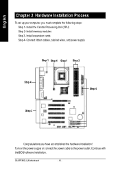
GA-8PE800(-L) Motherboard - 10 - English Chapter 2 Hardware Installation Process To set up your computer, you have accomplished the hardware installation! Continue with the BIOS/software installation. Install memory modules Step 3- Turn on the power supply or connect the power cable to the power outlet. Install the Central Processing Unit (CPU) Step 2- Connect ribbon cables, cabinet wires, and power supply Step 1 Step 4 Step 1 Step 2 Step 4 Step 4 Step 3 Congratulations you must complete the following steps: Step 1- Install expansion cards Step 4-
GA-8PE800(-L) Motherboard - 10 - English Chapter 2 Hardware Installation Process To set up your computer, you have accomplished the hardware installation! Continue with the BIOS/software installation. Install memory modules Step 3- Turn on the power supply or connect the power cable to the power outlet. Install the Central Processing Unit (CPU) Step 2- Connect ribbon cables, cabinet wires, and power supply Step 1 Step 4 Step 1 Step 2 Step 4 Step 4 Step 3 Congratulations you must complete the following steps: Step 1- Install expansion cards Step 4-
User Guide
Page 16
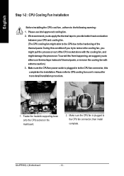
... power cable is plugged to the CPU fan connector, this from happening, we suggest you might pullthe processor out ofthe CPU socketalone with extreme caution.) 3. Please refer to the following warning: 1. GA-8PE800(-L) Motherboard - 12 - Make sure the CPU fan is plugged in to the CPU fan connector, than install complete. English Step 1-2 : CPU Cooling Fan Installation Before installing the CPU cool fan , adhere to CPUcooling fan user's manual for more detailinstallation procedure. 1. Fasten the heatsink supporting...
... power cable is plugged to the CPU fan connector, this from happening, we suggest you might pullthe processor out ofthe CPU socketalone with extreme caution.) 3. Please refer to the following warning: 1. GA-8PE800(-L) Motherboard - 12 - Make sure the CPU fan is plugged in to the CPU fan connector, than install complete. English Step 1-2 : CPU Cooling Fan Installation Before installing the CPU cool fan , adhere to CPUcooling fan user's manual for more detailinstallation procedure. 1. Fasten the heatsink supporting...

User Guide
Page 19
... the onboard AGP slot and press firmly down on the slot .Make sure yourAGP card is locked by the chipset. - 15 - Power on the card are indeed seated in the slot. 5. Hardware Installation Process Informing users that system might not boot up , indicating a non-supported graphics card is not supported by the small whitedrawable bar. AGP Card Please carefully pull outthe small white- Replace your computer's chassis cover...
... the onboard AGP slot and press firmly down on the slot .Make sure yourAGP card is locked by the chipset. - 15 - Power on the card are indeed seated in the slot. 5. Hardware Installation Process Informing users that system might not boot up , indicating a non-supported graphics card is not supported by the small whitedrawable bar. AGP Card Please carefully pull outthe small white- Replace your computer's chassis cover...
User Guide
Page 21
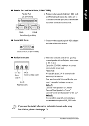
... jack. Hardware Installation Process COMA COMB Serial Port (9 pin Male) x Game /MIDI Ports Ø This connector supports joystick, MIDIkeyboard and other relate audio devices. Please note: You are able to page 76. - 17 - If you have 2 choose for 2-/4-/6-channel audio setup installation, please refer to use 2-/4-/6- Joystick/ MIDI (15 pin Female) y Audio Connectors Line Out (Front Speaker) MIC In (Center and Subwoofer) Line In (Rear Speaker) Ø After install onboard audio driver, you...
... jack. Hardware Installation Process COMA COMB Serial Port (9 pin Male) x Game /MIDI Ports Ø This connector supports joystick, MIDIkeyboard and other relate audio devices. Please note: You are able to page 76. - 17 - If you have 2 choose for 2-/4-/6-channel audio setup installation, please refer to use 2-/4-/6- Joystick/ MIDI (15 pin Female) y Audio Connectors Line Out (Front Speaker) MIC In (Center and Subwoofer) Line In (Rear Speaker) Ø After install onboard audio driver, you...
User Guide
Page 31
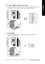
Please contact your nearest dealer for optional front USB cable. 2 10 19 Pin No. 1 2 3 4 5 6 7 8 9 10 Definition Power Power USB DXUSB DyUSB DX+ USB Dy+ GND GND No Pin NC 17) CI (CASE OPEN) This 2 pin connector allows your system to enable or disable the "case open" item in BIOS if the system case begin remove. Definition 1 1 Signal 2 GND - 27 - Hardware Installation Process Check the pin assignment while you connect the front USB cable. English 16) F_ USB1 / F_USB2(Front USB Connector, Yellow) Be careful with the polarity of the front USB connector. PinNo.
Please contact your nearest dealer for optional front USB cable. 2 10 19 Pin No. 1 2 3 4 5 6 7 8 9 10 Definition Power Power USB DXUSB DyUSB DX+ USB Dy+ GND GND No Pin NC 17) CI (CASE OPEN) This 2 pin connector allows your system to enable or disable the "case open" item in BIOS if the system case begin remove. Definition 1 1 Signal 2 GND - 27 - Hardware Installation Process Check the pin assignment while you connect the front USB cable. English 16) F_ USB1 / F_USB2(Front USB Connector, Yellow) Be careful with the polarity of the front USB connector. PinNo.
User Guide
Page 32
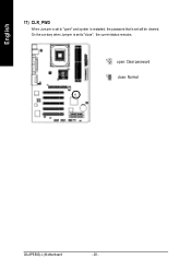
On the contrary when Jumper is set to "open" and system is restarted, the password that is set will be cleared. English 17) CLR_PWD When Jum per is set to "close", the current status remains. 1 open: Clear password 1 close: Normal GA-8PE800(-L) Motherboard - 28 -
On the contrary when Jumper is set to "open" and system is restarted, the password that is set will be cleared. English 17) CLR_PWD When Jum per is set to "close", the current status remains. 1 open: Clear password 1 close: Normal GA-8PE800(-L) Motherboard - 28 -

User Guide
Page 39
... types: auto type, and manual type. Note that the specifications of floppy disk driv e A or drive B that has been installed in the computer. The time is user-definable; Auto type which will be provided in . 5.25 inch AT-ty pe high-density driv e; 1.2M by te capacity . - 35 - If y ou select User Type, related information will automatically detect HDD type. Manual type is calculated base on the 24-hour military- C Drive A / Drive...
... types: auto type, and manual type. Note that the specifications of floppy disk driv e A or drive B that has been installed in the computer. The time is user-definable; Auto type which will be provided in . 5.25 inch AT-ty pe high-density driv e; 1.2M by te capacity . - 35 - If y ou select User Type, related information will automatically detect HDD type. Manual type is calculated base on the 24-hour military- C Drive A / Drive...
User Guide
Page 42
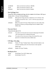
... stem w ith multi processors mode supported. (Default v alue) 8Disabled Disables CPU Hy per Threading Feature. Select y our boot dev ice priority by USB-HDD. Select y our boot dev ice priority by track number. C Boot Up Fl oppy Seek During POST, BIOS will determine the floppy disk drive installed is 40 or 80 tracks. 360 K type is not entered at the prompt. (Default v alue) CCPU Hyper-Threading 8Enabled Enables CPU Hy per Threading...
... stem w ith multi processors mode supported. (Default v alue) 8Disabled Disables CPU Hy per Threading Feature. Select y our boot dev ice priority by USB-HDD. Select y our boot dev ice priority by track number. C Boot Up Fl oppy Seek During POST, BIOS will determine the floppy disk drive installed is 40 or 80 tracks. 360 K type is not entered at the prompt. (Default v alue) CCPU Hyper-Threading 8Enabled Enables CPU Hy per Threading...
User Guide
Page 43
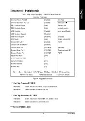
... Disable onboard 2nd channel IDE port. BIOS Setup English Integrated Peripherals CMOS Setup Utility -Copy right (C) 1984-2003 Aw ard Softw are Integrated Peripherals On-Chip Primary PCI IDE [Enabled] Item Help On-Chip Secondary PCI IDE [Enabled] Menu Lev el u IDE1 Conductor Cable [Auto] If a hard disk IDE2 Conductor Cable [Auto] controller card is USB Controller USB Key board Support USB Mouse Support AC97 Audio Onboard H/W LAN * Onboard LAN Boot ROM * Onboard Serial Port 1 Onboard Serial Port 2 Onboard Parallel Port Parallel Port Mode x ECP Mode Use DMA Game Port...
... Disable onboard 2nd channel IDE port. BIOS Setup English Integrated Peripherals CMOS Setup Utility -Copy right (C) 1984-2003 Aw ard Softw are Integrated Peripherals On-Chip Primary PCI IDE [Enabled] Item Help On-Chip Secondary PCI IDE [Enabled] Menu Lev el u IDE1 Conductor Cable [Auto] If a hard disk IDE2 Conductor Cable [Auto] controller card is USB Controller USB Key board Support USB Mouse Support AC97 Audio Onboard H/W LAN * Onboard LAN Boot ROM * Onboard Serial Port 1 Onboard Serial Port 2 Onboard Parallel Port Parallel Port Mode x ECP Mode Use DMA Game Port...

User Guide
Page 44
... by BIOS. (Default Value) 8ATA66/100 Set IDE2 Conductor Cable to ATA66/100 (Please make sure y our IDE dev ice and cable is compatible w ith ATA66/100). 8ATA33 Set IDE2 Conductor Cable to ATA33 (Please make sure your IDE dev ice and cable is compatible w ith ATA33). C USB Controller 8Enabled Enable USB Controller. (Default v alue) 8Disabled Disable USB Controller. GA-8PE800(-L) Motherboard - 40 - C USB Keyboard Support 8Enabled Enable USB Key board Support. 8Disabled Disable USB Key board Support. (Default v alue) C USB Mouse Support 8Enabled Enable USB Mouse...
... by BIOS. (Default Value) 8ATA66/100 Set IDE2 Conductor Cable to ATA66/100 (Please make sure y our IDE dev ice and cable is compatible w ith ATA66/100). 8ATA33 Set IDE2 Conductor Cable to ATA33 (Please make sure your IDE dev ice and cable is compatible w ith ATA33). C USB Controller 8Enabled Enable USB Controller. (Default v alue) 8Disabled Disable USB Controller. GA-8PE800(-L) Motherboard - 40 - C USB Keyboard Support 8Enabled Enable USB Key board Support. 8Disabled Disable USB Key board Support. (Default v alue) C USB Mouse Support 8Enabled Enable USB Mouse...

User Guide
Page 47
If use dual color LED, pow er LED w ill turn off. C Power LED i n S1 state 8Blinking In standby mode(S1), pow er LED w ill blink. (Default Value) 8Dual/OFF In standby mode(S1): a. If use single color LED, pow er LED w ill turn to another color. BIOS Setup b. English Power Management Setup CMOS Setup Utility -Copy right (C) 1984-2003 Aw ard Softw are Pow er Management Setup ACPI Suspend Ty pe [S1(POS)] Item Help...
If use dual color LED, pow er LED w ill turn off. C Power LED i n S1 state 8Blinking In standby mode(S1), pow er LED w ill blink. (Default Value) 8Dual/OFF In standby mode(S1): a. If use single color LED, pow er LED w ill turn to another color. BIOS Setup b. English Power Management Setup CMOS Setup Utility -Copy right (C) 1984-2003 Aw ard Softw are Pow er Management Setup ACPI Suspend Ty pe [S1(POS)] Item Help...
User Guide
Page 52
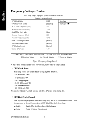
English Frequency/Voltage Control CMOS Setup Utility -Copy right (C) 1984-2003 Aw ard Softw are Frequency /Voltage Control CPU Clock Ratio [15X] Item Help CPU Host Clock Control [Disabled] Menu Lev el u øCPU Host Frequency (Mhz) 100 øFix ed PCI/AGP Frequency 33/66 Host/DRAM Clock ratio [Auto] Memory Frequency (Mhz) 266 PCI/AGP Frequency (Mhz) 33/66 DIMM Ov erVoltage Control [Normal] AGP Ov erVoltage Control [Normal] CPU Voltage Control [Normal] Normal CPU Vcore 1.5V higf: Mov e Enter:Select +/-/PU/PD...
English Frequency/Voltage Control CMOS Setup Utility -Copy right (C) 1984-2003 Aw ard Softw are Frequency /Voltage Control CPU Clock Ratio [15X] Item Help CPU Host Clock Control [Disabled] Menu Lev el u øCPU Host Frequency (Mhz) 100 øFix ed PCI/AGP Frequency 33/66 Host/DRAM Clock ratio [Auto] Memory Frequency (Mhz) 266 PCI/AGP Frequency (Mhz) 33/66 DIMM Ov erVoltage Control [Normal] AGP Ov erVoltage Control [Normal] CPU Voltage Control [Normal] Normal CPU Vcore 1.5V higf: Mov e Enter:Select +/-/PU/PD...

User Guide
Page 55
"Top Performance" w ill increase H/W w orking speed. English Top Performance CMOS Setup Utility -Copy right (C) 1984-2003 Aw ard Softw are }Standard CMOS Features Top Performance }Adv anced BIOS Features Load Fail-Safe Defaults }Integrated PeripThoepralPserformance Load Optimized Defaults }Pow er Management Setup Set Superv isor Passw ord Disabled n] }PnP/PCI Configurations Set User Passw ord Enabled }PC Health Status Sav e & Ex it Setup }Frequency /Voltage Control Ex it Without Sav ing ESC:Quit F8...
"Top Performance" w ill increase H/W w orking speed. English Top Performance CMOS Setup Utility -Copy right (C) 1984-2003 Aw ard Softw are }Standard CMOS Features Top Performance }Adv anced BIOS Features Load Fail-Safe Defaults }Integrated PeripThoepralPserformance Load Optimized Defaults }Pow er Management Setup Set Superv isor Passw ord Disabled n] }PnP/PCI Configurations Set User Passw ord Enabled }PC Health Status Sav e & Ex it Setup }Frequency /Voltage Control Ex it Without Sav ing ESC:Quit F8...
User Guide
Page 58
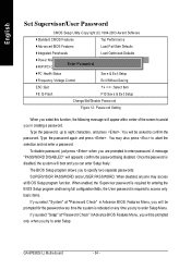
... screen to specify two separate passwords: SUPERVISOR PASSWORD and a USER PASSWORD. A message "PASSWORD DISABLED" will boot and you can enter Setup freely. GA-8PE800(-L) Motherboard - 54 - If youselect "Setup" at "Password Check" inAdvance BIOS Features Menu, you will be prompted only when you try to enter Setup. Type the password again and press . When enabled, the Supervisor password is required for entering the BIOS Setup program and having full configuration fields, the User password is required to access...
... screen to specify two separate passwords: SUPERVISOR PASSWORD and a USER PASSWORD. A message "PASSWORD DISABLED" will boot and you can enter Setup freely. GA-8PE800(-L) Motherboard - 54 - If youselect "Setup" at "Password Check" inAdvance BIOS Features Menu, you will be prompted only when you try to enter Setup. Type the password again and press . When enabled, the Supervisor password is required for entering the BIOS Setup program and having full configuration fields, the User password is required to access...
User Guide
Page 64
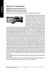
... responsible for future generations. They may make a test drive of "EasyTune 4" to change the system bus / AGP / Memory working frequency in computer field. Ifuser runs EasyTune 4 over -clocking methods, EasyTune 4doesn'trequire users tochange neitherBIOS norhardwareswitch/jumper setting; But have autoed and immediate CPU overclocking. "Advanced Mode", allows users to find the products supported list in the web site. *Any "Overclocking action" is at u ser's risk, Gig abyte...
... responsible for future generations. They may make a test drive of "EasyTune 4" to change the system bus / AGP / Memory working frequency in computer field. Ifuser runs EasyTune 4 over -clocking methods, EasyTune 4doesn'trequire users tochange neitherBIOS norhardwareswitch/jumper setting; But have autoed and immediate CPU overclocking. "Advanced Mode", allows users to find the products supported list in the web site. *Any "Overclocking action" is at u ser's risk, Gig abyte...

User Guide
Page 72
... Hea lth OK AMD- Use the arrows to enter BIOS setup main menu when system is bootup. All Rights Reserved STANDARD CMOS SETUP INTEGRATED PERIPHERALS BIOS FEATURES SETUP HARDWARE MONITOR & M ISC SETUP CHIPSET FEATURES SETUP SUPERVISOR PASSWORD POWER MANAGEMENT SETUP USER PASSWORD PNP / PCI CONFIGURATION IDE HDD AUTO DETECTION LOAD BIOS DEFAULTS SAVE & EXIT SETUP LOAD SETUP DEFAULTS EXIT WITHOUT SAVING ESC: Quit hifg : Select Item (Shift)F2 : Change Color F5: Old Values F6: Load BIOS Defaults F7: Load Setup Defaults F10:Save & Exit Tim e, Date , Hard Disk Type... Ath lo...
... Hea lth OK AMD- Use the arrows to enter BIOS setup main menu when system is bootup. All Rights Reserved STANDARD CMOS SETUP INTEGRATED PERIPHERALS BIOS FEATURES SETUP HARDWARE MONITOR & M ISC SETUP CHIPSET FEATURES SETUP SUPERVISOR PASSWORD POWER MANAGEMENT SETUP USER PASSWORD PNP / PCI CONFIGURATION IDE HDD AUTO DETECTION LOAD BIOS DEFAULTS SAVE & EXIT SETUP LOAD SETUP DEFAULTS EXIT WITHOUT SAVING ESC: Quit hifg : Select Item (Shift)F2 : Change Color F5: Old Values F6: Load BIOS Defaults F7: Load Setup Defaults F10:Save & Exit Tim e, Date , Hard Disk Type... Ath lo...


