User Guide
Page 1
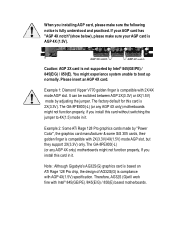
... : Although Gigabyte's AG32S(G) graphics card is based on ATi Rage 128 Pro chip, the design of AG32S(G) is compliance with 2X(3.3V)/4X(1.5V) mode AGP slot, but they support 2X(3.3V) only. Please insert an AGP 4X card. If your AGP card is AGP 4X (1.5V). The GA-8PE800(-L) (or ...is compatible with Intel® 845(GE/PE) /845(E/G) / 850(E) based motherboards. Caution: AGP 2X card is not supported by adjusting the jumper. The GA-8PE800(-L) (or any AGP 4X only) motherboards might experience system unable to 4X(1.5) mode in it . Therefore, AG32S (G)will work fine with 2X/4X mode ...
... : Although Gigabyte's AG32S(G) graphics card is based on ATi Rage 128 Pro chip, the design of AG32S(G) is compliance with 2X(3.3V)/4X(1.5V) mode AGP slot, but they support 2X(3.3V) only. Please insert an AGP 4X card. If your AGP card is AGP 4X (1.5V). The GA-8PE800(-L) (or ...is compatible with Intel® 845(GE/PE) /845(E/G) / 850(E) based motherboards. Caution: AGP 2X card is not supported by adjusting the jumper. The GA-8PE800(-L) (or any AGP 4X only) motherboards might experience system unable to 4X(1.5) mode in it . Therefore, AG32S (G)will work fine with 2X/4X mode ...
User Guide
Page 3
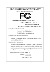
...;ding GMbH Ausschlager Weg 41, 1F, 20537 Hamburg, Germany declare that the product ( description of the apparatus, system, installation to which it refers) Mother Board GA-8PE800(-L) is in conformity with (reference to the specification under which conformity is declared) in accordance with 89/336 EEC-EMC Directive Limits and methods of...
...;ding GMbH Ausschlager Weg 41, 1F, 20537 Hamburg, Germany declare that the product ( description of the apparatus, system, installation to which it refers) Mother Board GA-8PE800(-L) is in conformity with (reference to the specification under which conformity is declared) in accordance with 89/336 EEC-EMC Directive Limits and methods of...
User Guide
Page 4
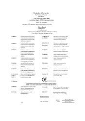
... part 15 of Industry, CA 91748 Phone/Fax No: (818) 854-9338/ (818) 854-9339 hereby declares that the product Product Name: Motherboard Model Number: GA-8PE800(-L) Conforms to the following two conditions: (1) This device may not cause harmful and (2) this device must accept any inference received, including that may cause undesired...
... part 15 of Industry, CA 91748 Phone/Fax No: (818) 854-9338/ (818) 854-9339 hereby declares that the product Product Name: Motherboard Model Number: GA-8PE800(-L) Conforms to the following two conditions: (1) This device may not cause harmful and (2) this device must accept any inference received, including that may cause undesired...

User Guide
Page 5
GA-8PE800(-L) P4 Titan Motherboard USER'S MANUAL Pentium®4 Processor Motherboard Rev. 1102 12ME-8PE800-1102
GA-8PE800(-L) P4 Titan Motherboard USER'S MANUAL Pentium®4 Processor Motherboard Rev. 1102 12ME-8PE800-1102
User Guide
Page 6
English Table of Content Item Checklist 4 Chapter 1 Introduction 5 Features Summary 5 GA-8PE800(-L) Motherboard Layout 7 Block Diagram 8 Chapter 2 Hardware Installation Process 10 Step 1: Install the Central Processing Unit (CPU 11 Step 1-1: CPU Installation 11 Step 1-2 : CPU Cooling Fan ... 31 The Main Menu (For example: BIOS Ver. : F7a 32 Standard CMOS Features 34 Advanced BIOS Features 37 Integrated Peripherals 39 Power Management Setup 43 GA-8PE800(-L) Motherboard - 2 -
English Table of Content Item Checklist 4 Chapter 1 Introduction 5 Features Summary 5 GA-8PE800(-L) Motherboard Layout 7 Block Diagram 8 Chapter 2 Hardware Installation Process 10 Step 1: Install the Central Processing Unit (CPU 11 Step 1-1: CPU Installation 11 Step 1-2 : CPU Cooling Fan ... 31 The Main Menu (For example: BIOS Ver. : F7a 32 Standard CMOS Features 34 Advanced BIOS Features 37 Integrated Peripherals 39 Power Management Setup 43 GA-8PE800(-L) Motherboard - 2 -
User Guide
Page 8
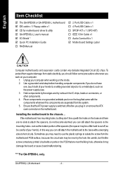
...motherboard PCB surface, because the circuit wire may be near the fixing hole, otherwise it may be careful ofyour hands). GA-8PE800(-L) Motherboard - 4 - To protect them againstdamage from the system. 5. Use a grounded wrist strap before handling computer... the IC chips, leads or connectors, or other components. 4. English Item Checklist þ The GA-8PE800 or GA-8PE800-L motherboard þ IDE cable x 1/ Floppy cable x 1 þ CD for motherboard driver & utility þ GA-8PE800(-L) user's manual þ I/O Shield * þ Quick PC Installation Guide o RAID Manual þ...
...motherboard PCB surface, because the circuit wire may be near the fixing hole, otherwise it may be careful ofyour hands). GA-8PE800(-L) Motherboard - 4 - To protect them againstdamage from the system. 5. Use a grounded wrist strap before handling computer... the IC chips, leads or connectors, or other components. 4. English Item Checklist þ The GA-8PE800 or GA-8PE800-L motherboard þ IDE cable x 1/ Floppy cable x 1 þ CD for motherboard driver & utility þ GA-8PE800(-L) user's manual þ I/O Shield * þ Quick PC Installation Guide o RAID Manual þ...
User Guide
Page 10
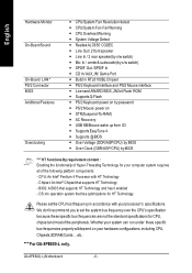
...Warning - SPDIF Out /SPDIF In - Licensed AWARD BIOS, 2M bit Flash ROM - STR(Suspend-To-RAM) - AC Recovery - Supports @BIOS - GA-8PE800(-L) Motherboard - 6 - CPU/System Fan Revolution detect - Build in accordance with HT Technology - Supports Q-Flash - PS/2 Mouse power on your system...Voltage (DDR/AGP/CPU) by s/w switch) - Line In / 2 rear speaker(by BIOS - PS/2 Keyboard power on by s/w switch) - "*" For GA-8PE800-L only. CPU Overheat Warning - System Voltage Detect - We don't recommend you to set the CPU host frequency in RTL8100BL Chipset - BIOS: A BIOS that ...
...Warning - SPDIF Out /SPDIF In - Licensed AWARD BIOS, 2M bit Flash ROM - STR(Suspend-To-RAM) - AC Recovery - Supports @BIOS - GA-8PE800(-L) Motherboard - 6 - CPU/System Fan Revolution detect - Build in accordance with HT Technology - Supports Q-Flash - PS/2 Mouse power on your system...Voltage (DDR/AGP/CPU) by s/w switch) - Line In / 2 rear speaker(by BIOS - PS/2 Keyboard power on by s/w switch) - "*" For GA-8PE800-L only. CPU Overheat Warning - System Voltage Detect - We don't recommend you to set the CPU host frequency in RTL8100BL Chipset - BIOS: A BIOS that ...
User Guide
Page 11
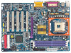
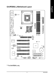
English GA-8PE800(-L) Motherboard Layout KB_MS USB_LAN * C PU_FAN ATX COMA SOC KET478 COMB LPT ATX_12V GA-8PE800 DDR1 DDR2 DDR3 MIC_IN LINE_OUT LINE_IN GAME SUR_CEN -L F_AU DIO AGP_LED RTL8100BL * C D_IN AU X_IN C ODEC P4 Titan IT8 712 SPDIF_IO CI F_U SB1 845P E FD D AGP PCI1 PCI2 CL R_P WD PCI3 ICH 4 SYS _FAN PCI4 PCI5 BIOS F_U SB2 F_PAN EL BAT IDE2 IDE1 PWR_LED "*" For GA-8PE800-L only. - 7 - Introduction
English GA-8PE800(-L) Motherboard Layout KB_MS USB_LAN * C PU_FAN ATX COMA SOC KET478 COMB LPT ATX_12V GA-8PE800 DDR1 DDR2 DDR3 MIC_IN LINE_OUT LINE_IN GAME SUR_CEN -L F_AU DIO AGP_LED RTL8100BL * C D_IN AU X_IN C ODEC P4 Titan IT8 712 SPDIF_IO CI F_U SB1 845P E FD D AGP PCI1 PCI2 CL R_P WD PCI3 ICH 4 SYS _FAN PCI4 PCI5 BIOS F_U SB2 F_PAN EL BAT IDE2 IDE1 PWR_LED "*" For GA-8PE800-L only. - 7 - Introduction
User Guide
Page 14
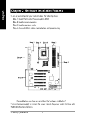
Install expansion cards Step 4- Turn on the power supply or connect the power cable to the power outlet. GA-8PE800(-L) Motherboard - 10 - English Chapter 2 Hardware Installation Process To set up your computer, you have accomplished the hardware installation! Install memory modules Step 3- Connect ribbon cables, cabinet wires, and power supply Step 1 Step 4 Step 1 Step 2 Step 4 Step 4 Step 3 Congratulations you must complete the following steps: Step 1- Continue with the BIOS/software installation. Install the Central Processing Unit (CPU) Step 2-
Install expansion cards Step 4- Turn on the power supply or connect the power cable to the power outlet. GA-8PE800(-L) Motherboard - 10 - English Chapter 2 Hardware Installation Process To set up your computer, you have accomplished the hardware installation! Install memory modules Step 3- Connect ribbon cables, cabinet wires, and power supply Step 1 Step 4 Step 1 Step 2 Step 4 Step 4 Step 3 Congratulations you must complete the following steps: Step 1- Continue with the BIOS/software installation. Install the Central Processing Unit (CPU) Step 2-
User Guide
Page 16
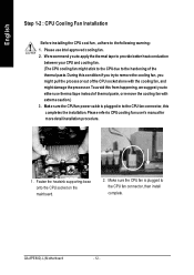
... CPU cool fan , adhere to CPUcooling fan user's manual for more detailinstallation procedure. 1. Fasten the heatsink supporting-base onto the CPU socket on the mainboard. 2. GA-8PE800(-L) Motherboard - 12 - Please refer to the following warning: 1. We recommend you to apply the thermal tape to the hardening of the thermal paste.During this...
... CPU cool fan , adhere to CPUcooling fan user's manual for more detailinstallation procedure. 1. Fasten the heatsink supporting-base onto the CPU socket on the mainboard. 2. GA-8PE800(-L) Motherboard - 12 - Please refer to the following warning: 1. We recommend you to apply the thermal tape to the hardening of the thermal paste.During this...
User Guide
Page 18
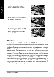
DDR Introduction Established on the existing SDRAM infrastructure, yet makes awesome advances in one direction. 2. GA-8PE800(-L) Motherboard - 14 - Close the plastic clip at both edges of the DIMM slots to lock the DIMM module. With peak bandwidth of 2.664GB per second, ...
DDR Introduction Established on the existing SDRAM infrastructure, yet makes awesome advances in one direction. 2. GA-8PE800(-L) Motherboard - 14 - Close the plastic clip at both edges of the DIMM slots to lock the DIMM module. With peak bandwidth of 2.664GB per second, ...
User Guide
Page 20
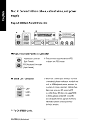
v USB & LAN * Connector LAN * USB 0 USB 1 "*" For GA-8PE800-L only. Also make sure your OS or device(s) vendors. - 16 - Have a standard USB interface. For more info rmation please contact your OS supports USB con .../2 Keyboard and PS/2 Mouse Connector PS/2 Mouse Connector (6 pin Female) PS/2 Keyboard Connector (6 pin Female) Ø This connector supports standard PS/2 keyboard and PS/2 mouse. GA-8PE800(-L) Motherboard Ø Before you connect your device(s) into USB connector(s), please ma ke sure your OS d oes n ot sup port USB controller, please contactOS vendor...
v USB & LAN * Connector LAN * USB 0 USB 1 "*" For GA-8PE800-L only. Also make sure your OS or device(s) vendors. - 16 - Have a standard USB interface. For more info rmation please contact your OS supports USB con .../2 Keyboard and PS/2 Mouse Connector PS/2 Mouse Connector (6 pin Female) PS/2 Keyboard Connector (6 pin Female) Ø This connector supports standard PS/2 keyboard and PS/2 mouse. GA-8PE800(-L) Motherboard Ø Before you connect your device(s) into USB connector(s), please ma ke sure your OS d oes n ot sup port USB controller, please contactOS vendor...
User Guide
Page 22
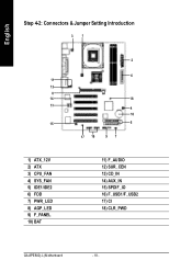
English Step 4-2: Connectors & Jumper Setting Introduction 31 11 12 8 14 13 15 1) ATX_12V 2) ATX 3) CPU_FAN 4) SYS_FAN 5) IDE1/IDE2 6) FDD 7) PWR_LED 8) AGP_LED 9) F_PANEL 10) BAT 2 6 18 4 10 5 17 16 97 11) F_AUDIO 12) SUR_CEN 13) CD_IN 14) AUX_IN 15) SPDIF_IO 16) F_USB1/F_USB2 17) CI 18) CLR_PWD GA-8PE800(-L) Motherboard - 18 -
English Step 4-2: Connectors & Jumper Setting Introduction 31 11 12 8 14 13 15 1) ATX_12V 2) ATX 3) CPU_FAN 4) SYS_FAN 5) IDE1/IDE2 6) FDD 7) PWR_LED 8) AGP_LED 9) F_PANEL 10) BAT 2 6 18 4 10 5 17 16 97 11) F_AUDIO 12) SUR_CEN 13) CD_IN 14) AUX_IN 15) SPDIF_IO 16) F_USB1/F_USB2 17) CI 18) CLR_PWD GA-8PE800(-L) Motherboard - 18 -
User Guide
Page 24
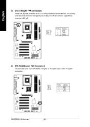
English 3) CPU_FAN (CPU FAN Connector) Please note, a proper installation of the CPU cooler is essential to 600 mA. PinNo. Definition 1 GND 1 2 +12V 3 Sense GA-8PE800(-L) Motherboard - 20 - current up to prevent the CPU from running under abnormal condition or damaged by overheating.The CPU fan connector supports Max. PinNo. Definition 1 1 GND 2 +12V 3 Sense 4) SYS_FAN (System FAN Connector) This connector allows you to link with the cooling fan on the system case to lower the system temperature.
English 3) CPU_FAN (CPU FAN Connector) Please note, a proper installation of the CPU cooler is essential to 600 mA. PinNo. Definition 1 GND 1 2 +12V 3 Sense GA-8PE800(-L) Motherboard - 20 - current up to prevent the CPU from running under abnormal condition or damaged by overheating.The CPU fan connector supports Max. PinNo. Definition 1 1 GND 2 +12V 3 Sense 4) SYS_FAN (System FAN Connector) This connector allows you to link with the cooling fan on the system case to lower the system temperature.
User Guide
Page 26
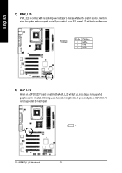
Informing users that system might notboot up , indicating a nonsupported graphics card is inserted. If you use dual color LED, power LED will blink when the system enters suspend mode. English 7) PWR_LED PWR_LED is connect with the system power indicator to AGP 2X (3.3V) is not supported by the chipset. -+ GA-8PE800(-L) Motherboard - 22 - It will turn to another color. 1 PinNo. Definition 1 MPD+ 2 MPD- 3 MPD- 8) AGP_LED When an AGP 2X (3.3V) card is installed the AGP_LED will light up normally due to indicate whether the system is on/off.
Informing users that system might notboot up , indicating a nonsupported graphics card is inserted. If you use dual color LED, power LED will blink when the system enters suspend mode. English 7) PWR_LED PWR_LED is connect with the system power indicator to AGP 2X (3.3V) is not supported by the chipset. -+ GA-8PE800(-L) Motherboard - 22 - It will turn to another color. 1 PinNo. Definition 1 MPD+ 2 MPD- 3 MPD- 8) AGP_LED When an AGP 2X (3.3V) card is installed the AGP_LED will light up normally due to indicate whether the system is on/off.
User Guide
Page 28
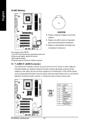
v Dispose of used batteries according to play sound. Definition 1 MIC 2 GND 10 9 3 REF 4 POWER 21 5 FrontAudio(R) 6 RearAudio(R) 7 Reserved 8 NoPin 9 FrontAudio(L) 10 RearAudio(L) GA-8PE800(-L) Motherboard - 24 - If you want to erase CM OS... 1.Turn OFF the computer and unplug the power cord. 2.Remove the battery, wait for 30 second. 3....
v Dispose of used batteries according to play sound. Definition 1 MIC 2 GND 10 9 3 REF 4 POWER 21 5 FrontAudio(R) 6 RearAudio(R) 7 Reserved 8 NoPin 9 FrontAudio(L) 10 RearAudio(L) GA-8PE800(-L) Motherboard - 24 - If you want to erase CM OS... 1.Turn OFF the computer and unplug the power cord. 2.Remove the battery, wait for 30 second. 3....
User Guide
Page 30
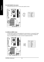
PinNo. Use SPDIF IN feature only when your stereo system has digital input function. Definition 1 1 AUX-L 2 GND 3 GND 4 AUX_R 15) SPDIF_IO (SPDIF In/Out) The SPDIF output is capable of providing digital audio to external speakers or compressed AC3 data to the connector. English 14) AUX_IN (AUX In Connector) Connect other device(such as PCI TV Tunner audio out)to an external Dolby Digital Decoder. Use this feature only when your device has digital output function. 26 15 Pin No. 1 2 3 4 5 6 Definition VCC No Pin SPDIF SPDIFI GND GND GA-8PE800(-L) Motherboard - 26 -
PinNo. Use SPDIF IN feature only when your stereo system has digital input function. Definition 1 1 AUX-L 2 GND 3 GND 4 AUX_R 15) SPDIF_IO (SPDIF In/Out) The SPDIF output is capable of providing digital audio to external speakers or compressed AC3 data to the connector. English 14) AUX_IN (AUX In Connector) Connect other device(such as PCI TV Tunner audio out)to an external Dolby Digital Decoder. Use this feature only when your device has digital output function. 26 15 Pin No. 1 2 3 4 5 6 Definition VCC No Pin SPDIF SPDIFI GND GND GA-8PE800(-L) Motherboard - 26 -
User Guide
Page 32
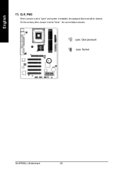
English 17) CLR_PWD When Jum per is set to "close : Normal GA-8PE800(-L) Motherboard - 28 - On the contrary when Jumper is set to "open : Clear password 1 close ", the current status remains. 1 open " and system is restarted, the password that is set will be cleared.
English 17) CLR_PWD When Jum per is set to "close : Normal GA-8PE800(-L) Motherboard - 28 - On the contrary when Jumper is set to "open : Clear password 1 close ", the current status remains. 1 open " and system is restarted, the password that is set will be cleared.
User Guide
Page 36
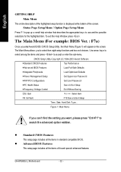
... appropriate keys to accept or enter the sub-menu. The Main Menu (For example: BIOS Ver. : F7a) Once you to search th e advanced optio n widden. GA-8PE800(-L) Motherboard - 32 - To exit the Help Window press . Figure 1: Main Menu If you can't find the set ting you want, p lease press "Ctrl+F1" to...
... appropriate keys to accept or enter the sub-menu. The Main Menu (For example: BIOS Ver. : F7a) Once you to search th e advanced optio n widden. GA-8PE800(-L) Motherboard - 32 - To exit the Help Window press . Figure 1: Main Menu If you can't find the set ting you want, p lease press "Ctrl+F1" to...
User Guide
Page 38
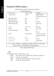
... only 8Month 8Day 8Year The month, Jan. to Dec. 1 to 31 (or max imum allow ed in the month) The y ear, from 1999 through 2098 GA-8PE800(-L) Motherboard - 34 - to Sat, determined by the BIOS and is , , , . 8Week The w eek, from 1 to 31 (or the max imum allow ed in . None Disabled...
... only 8Month 8Day 8Year The month, Jan. to Dec. 1 to 31 (or max imum allow ed in the month) The y ear, from 1999 through 2098 GA-8PE800(-L) Motherboard - 34 - to Sat, determined by the BIOS and is , , , . 8Week The w eek, from 1 to 31 (or the max imum allow ed in . None Disabled...

