
Manual
Page 1
...utility to enable the Intel Smart Response Technology • The Intel Smart Response Technology requires a computer system with an Intel Z68 Chipset-based motherboard and an Intel Core series CPU. • The operating system must be installed to make it work as a cache of the hard ...English Follow the steps below to enter BIOS Setup during the POST (Power-On Self-Test). Enabling RAID mode in BIOS Setup: Turn on the motherboard you have installed the operating system before enabling the Smart Response Technology. 1. Installing a conventional SATA hard disk and a solid-state drive (SSD...
...utility to enable the Intel Smart Response Technology • The Intel Smart Response Technology requires a computer system with an Intel Z68 Chipset-based motherboard and an Intel Core series CPU. • The operating system must be installed to make it work as a cache of the hard ...English Follow the steps below to enter BIOS Setup during the POST (Power-On Self-Test). Enabling RAID mode in BIOS Setup: Turn on the motherboard you have installed the operating system before enabling the Smart Response Technology. 1. Installing a conventional SATA hard disk and a solid-state drive (SSD...

Manual
Page 2
..., including the Intel Rapid Storage Technology driver. Make sure the Intel Rapid Storage Technology driver version is complete, use the "Xpress Install" function of the motherboard driver disk to enable the Intel Smart Response Technology: Step 1: After completing the steps above . 4. Installing the operating system and drivers to the SATA disk...
..., including the Intel Rapid Storage Technology driver. Make sure the Intel Rapid Storage Technology driver version is complete, use the "Xpress Install" function of the motherboard driver disk to enable the Intel Smart Response Technology: Step 1: After completing the steps above . 4. Installing the operating system and drivers to the SATA disk...
Manual
Page 2
Motherboard GA-Z68X-UD4-B3 Apr. 8, 2011 Motherboard GA-Z68X-UD4-B3 Apr. 8, 2011
Motherboard GA-Z68X-UD4-B3 Apr. 8, 2011 Motherboard GA-Z68X-UD4-B3 Apr. 8, 2011
Manual
Page 3
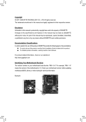
Disclaimer Information in this manual may be made by GIGABYTE without GIGABYTE's prior written permission. Check your motherboard looks like this manual may be reproduced, copied, translated, transmitted, or published in the use of this manual ...in any means without prior notice. For product-related information, check on our website at: http://www.gigabyte.com Identifying Your Motherboard Revision The revision number on your motherboard revision before updating motherboard BIOS, drivers, or when looking for technical information. Copyright © 2011 GIGA-BYTE TECHNOLOGY CO., ...
Disclaimer Information in this manual may be made by GIGABYTE without GIGABYTE's prior written permission. Check your motherboard looks like this manual may be reproduced, copied, translated, transmitted, or published in the use of this manual ...in any means without prior notice. For product-related information, check on our website at: http://www.gigabyte.com Identifying Your Motherboard Revision The revision number on your motherboard revision before updating motherboard BIOS, drivers, or when looking for technical information. Copyright © 2011 GIGA-BYTE TECHNOLOGY CO., ...
Manual
Page 4
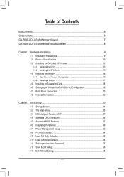
Table of Contents Box Contents...6 Optional Items...6 GA-Z68X-UD4-B3 Motherboard Layout 7 GA-Z68X-UD4-B3 Motherboard Block Diagram 8 Chapter 1 Hardware Installation 9 1-1 Installation Precautions 9 1-2 Product Specifications 10 1-3 Installing the CPU and CPU Cooler 13 1-3-1 Installing the CPU 13 1-3-2 Installing the CPU Cooler ...
Table of Contents Box Contents...6 Optional Items...6 GA-Z68X-UD4-B3 Motherboard Layout 7 GA-Z68X-UD4-B3 Motherboard Block Diagram 8 Chapter 1 Hardware Installation 9 1-1 Installation Precautions 9 1-2 Product Specifications 10 1-3 Installing the CPU and CPU Cooler 13 1-3-1 Installing the CPU 13 1-3-2 Installing the CPU Cooler ...
Manual
Page 6
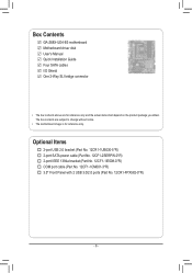
... IEEE 1394a bracket (Part No. 12CF1-1IE008-0*R) COM port cable (Part No. 12CF1-1CM001-3*R) 3.5" Front Panel with 2 USB 3.0/2.0 ports (Part No. 12CR1-FPX582-0*R) - 6 - Box Contents GA-Z68X-UD4-B3 motherboard Motherboard driver disk User's Manual Quick Installation Guide Four SATA cables I/O Shield One 2-Way SLI bridge connector • The box contents above are subject to change...
... IEEE 1394a bracket (Part No. 12CF1-1IE008-0*R) COM port cable (Part No. 12CF1-1CM001-3*R) 3.5" Front Panel with 2 USB 3.0/2.0 ports (Part No. 12CR1-FPX582-0*R) - 6 - Box Contents GA-Z68X-UD4-B3 motherboard Motherboard driver disk User's Manual Quick Installation Guide Four SATA cables I/O Shield One 2-Way SLI bridge connector • The box contents above are subject to change...
Manual
Page 7
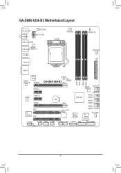
GA-Z68X-UD4-B3 Motherboard Layout KB_MS_USB R_SPDIF SYS_FAN1 ATX_12V_2X4 USB_1394_ESATA Marvell USB_ESATA 88SE9172 R_USB30 USB_LAN LGA1155 CPU_FAN PHASE LED PWR_FAN ATX AUDIO Realtek RTL8111E Etron EJ168 PCIEX16 B_BIOS GA-Z68X-UD4-B3 M_BIOS PCIEX1_1 DDR3_4 DDR3_2 DDR3_3 DDR3_1 Marvell GSATA3_7 88SE9172 CODEC PCIEX1_2 PCIEX8 PCI1 VIA VT6308 PCI2 GSATA3_6 SATA3_1 Intel® Z68 SATA3_0 BAT SATA2_3 SATA2_2 PCIe to PCI Bridge Etron EJ168 SATA2_5 SATA2_4 iTE IT8728 SYS_FAN2 F_AUDIO CLR_CMOS F_1394 COMA F_USB3 F_USB2 F_USB1 F_USB30 TPM F_PANEL SPDIF_O - 7 -
GA-Z68X-UD4-B3 Motherboard Layout KB_MS_USB R_SPDIF SYS_FAN1 ATX_12V_2X4 USB_1394_ESATA Marvell USB_ESATA 88SE9172 R_USB30 USB_LAN LGA1155 CPU_FAN PHASE LED PWR_FAN ATX AUDIO Realtek RTL8111E Etron EJ168 PCIEX16 B_BIOS GA-Z68X-UD4-B3 M_BIOS PCIEX1_1 DDR3_4 DDR3_2 DDR3_3 DDR3_1 Marvell GSATA3_7 88SE9172 CODEC PCIEX1_2 PCIEX8 PCI1 VIA VT6308 PCI2 GSATA3_6 SATA3_1 Intel® Z68 SATA3_0 BAT SATA2_3 SATA2_2 PCIe to PCI Bridge Etron EJ168 SATA2_5 SATA2_4 iTE IT8728 SYS_FAN2 F_AUDIO CLR_CMOS F_1394 COMA F_USB3 F_USB2 F_USB1 F_USB30 TPM F_PANEL SPDIF_O - 7 -
Manual
Page 8
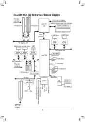
GA-Z68X-UD4-B3 Motherboard Block Diagram PCIe CLK (100 MHz) 1 PCI Express x16 or 2 PCI Express x8 LGA1155 CPU CPU CLK+/- (100 MHz) DDR3 2133/1866/1600/1333/1066 ...
GA-Z68X-UD4-B3 Motherboard Block Diagram PCIe CLK (100 MHz) 1 PCI Express x16 or 2 PCI Express x8 LGA1155 CPU CPU CLK+/- (100 MHz) DDR3 2133/1866/1600/1333/1066 ...
Manual
Page 9
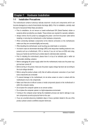
...an ESD wrist strap, keep your hands dry and first touch a metal object to eliminate static electricity. •• Prior to installing the motherboard, please have it on top of an antistatic pad or within an electrostatic shielding container. •• Before unplugging the power supply cable ...components as well as physical harm to the user. •• If you are connected tightly and securely. •• When handling the motherboard, avoid touching any metal leads or connectors. •• It is best to wear an electrostatic discharge (ESD) wrist strap when handling electronic ...
...an ESD wrist strap, keep your hands dry and first touch a metal object to eliminate static electricity. •• Prior to installing the motherboard, please have it on top of an antistatic pad or within an electrostatic shielding container. •• Before unplugging the power supply cable ...components as well as physical harm to the user. •• If you are connected tightly and securely. •• When handling the motherboard, avoid touching any metal leads or connectors. •• It is best to wear an electrostatic discharge (ESD) wrist strap when handling electronic ...
Manual
Page 12
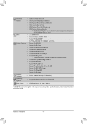
...138; Support for Xpress Install ŠŠ Support for Xpress Recovery2 ŠŠ Support for EasyTune * Available functions in EasyTune may differ by motherboard model. ŠŠ Support for Dynamic Energy Saver™ 2 ŠŠ Support for Smart 6™ ŠŠ Support for Auto ...138;Š Support for Microsoft® Windows 7/Vista/XP Form Factor ŠŠ ATX Form Factor; 30.5cm x 24.4cm * GIGABYTE reserves the right to make any changes to the product specifications and product-related information without prior notice. Hardware ŠŠ System voltage ...
...138; Support for Xpress Install ŠŠ Support for Xpress Recovery2 ŠŠ Support for EasyTune * Available functions in EasyTune may differ by motherboard model. ŠŠ Support for Dynamic Energy Saver™ 2 ŠŠ Support for Smart 6™ ŠŠ Support for Auto ...138;Š Support for Microsoft® Windows 7/Vista/XP Form Factor ŠŠ ATX Form Factor; 30.5cm x 24.4cm * GIGABYTE reserves the right to make any changes to the product specifications and product-related information without prior notice. Hardware ŠŠ System voltage ...

Manual
Page 13
...(Or you may occur. •• Set the CPU host frequency in accordance with the CPU specifications. Locate the alignment keys on the motherboard CPU socket and the notches on the CPU - 13 - The CPU cannot be set the frequency beyond hardware specifications since it does not ...•• Always turn on the surface of thermal grease on the computer if the CPU cooler is not recommended that the motherboard supports the CPU. (Go to GIGABYTE's website for the peripherals. If you wish to set beyond the standard specifications, please do so according to prevent hardware damage...
...(Or you may occur. •• Set the CPU host frequency in accordance with the CPU specifications. Locate the alignment keys on the motherboard CPU socket and the notches on the CPU - 13 - The CPU cannot be set the frequency beyond hardware specifications since it does not ...•• Always turn on the surface of thermal grease on the computer if the CPU cooler is not recommended that the motherboard supports the CPU. (Go to GIGABYTE's website for the peripherals. If you wish to set beyond the standard specifications, please do so according to prevent hardware damage...
Manual
Page 14
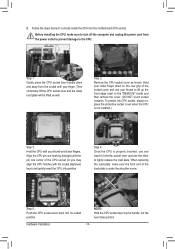
... the other to the "REMOVE" mark) and then remove the cover. (DO NOT touch socket contacts. Step 5: Push the CPU socket lever back into the motherboard CPU socket. B. To protect the CPU socket, always replace the protective socket cover when the CPU is under the shoulder screw. Step 2: Remove the CPU...
... the other to the "REMOVE" mark) and then remove the cover. (DO NOT touch socket contacts. Step 5: Push the CPU socket lever back into the motherboard CPU socket. B. To protect the CPU socket, always replace the protective socket cover when the CPU is under the shoulder screw. Step 2: Remove the CPU...
Manual
Page 15
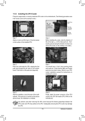
.... Step 6: Finally, attach the power connector of arrow is to remove the cooler, on the contrary, is to the CPU fan header (CPU_FAN) on the motherboard. Step 2: Before installing the cooler, note the direction of the arrow sign on the male push pin. (Turning the push pin along the direction of... the CPU cooler to install.) Step 3: Place the cooler atop the CPU, aligning the four push pins through the pin holes on the motherboard. Use extreme care when removing the CPU cooler because the thermal grease/tape between the CPU cooler and CPU may damage the CPU. - 15 -
.... Step 6: Finally, attach the power connector of arrow is to remove the cooler, on the contrary, is to the CPU fan header (CPU_FAN) on the motherboard. Step 2: Before installing the cooler, note the direction of the arrow sign on the male push pin. (Turning the push pin along the direction of... the CPU cooler to install.) Step 3: Place the cooler atop the CPU, aligning the four push pins through the pin holes on the motherboard. Use extreme care when removing the CPU cooler because the thermal grease/tape between the CPU cooler and CPU may damage the CPU. - 15 -
Manual
Page 16
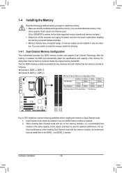
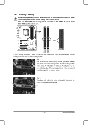
...capacity, brand, speed, and chips be used . (Go to GIGABYTE's website for optimum performance. The four DDR3 memory sockets are unable to insert the memory, switch the direction. 1-4-1 Dual Channel Memory Configuration This motherboard provides four DDR3 memory sockets and supports Dual Channel Technology. For ... the specifications and capacity of the memory. A memory module can be installed in only one DDR3 memory module is recommended that the motherboard supports the memory. DS/SS DS/SS DDR3_2 DS/SS - Hardware Installation - 16 - Dual Channel mode cannot be enabled if ...
...capacity, brand, speed, and chips be used . (Go to GIGABYTE's website for optimum performance. The four DDR3 memory sockets are unable to insert the memory, switch the direction. 1-4-1 Dual Channel Memory Configuration This motherboard provides four DDR3 memory sockets and supports Dual Channel Technology. For ... the specifications and capacity of the memory. A memory module can be installed in only one DDR3 memory module is recommended that the motherboard supports the memory. DS/SS DS/SS DDR3_2 DS/SS - Hardware Installation - 16 - Dual Channel mode cannot be enabled if ...
Manual
Page 17
..., push down on the memory and insert it can only fit in one direction. DDR3_4 DDR3_2 DDR3_3 DDR3_1 - 17 - Place the memory module on this motherboard. Step 2: The clips at both ends of the memory socket. Spread the retaining clips at both ends of the socket will snap into the memory...
..., push down on the memory and insert it can only fit in one direction. DDR3_4 DDR3_2 DDR3_3 DDR3_1 - 17 - Place the memory module on this motherboard. Step 2: The clips at both ends of the memory socket. Spread the retaining clips at both ends of the socket will snap into the memory...
Manual
Page 18
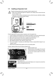
... turn off the computer and unplug the power cord from the power outlet before you begin to install an expansion card: • Make sure the motherboard supports the expansion card. Hardware Installation - 18 - Remove the metal slot cover from the slot. If necessary, go to BIOS Setup to release the card...
... turn off the computer and unplug the power cord from the power outlet before you begin to install an expansion card: • Make sure the motherboard supports the expansion card. Hardware Installation - 18 - Remove the metal slot cover from the slot. If necessary, go to BIOS Setup to release the card...
Manual
Page 19
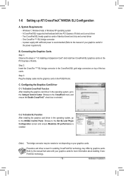
System Requirements - A CrossFireX/SLI-supported motherboard with sufficient power is recommended (Refer to the NVIDIA Control Panel. Connecting the Graphics Cards Step 1: Observe the steps in the operating system, go to ...
System Requirements - A CrossFireX/SLI-supported motherboard with sufficient power is recommended (Refer to the NVIDIA Control Panel. Connecting the Graphics Cards Step 1: Observe the steps in the operating system, go to ...
Manual
Page 20
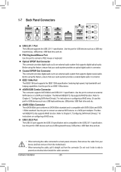
.... Refer to prevent an electrical short inside the cable connector. The Marvell 88SE9172 chip supports RAID function. Do not rock it straight out from the motherboard. •• When removing the cable, pull it side to side to Chapter 5, "Configuring SATA Hard Drive(s)," for USB devices such as a USB keyboard/mouse...
.... Refer to prevent an electrical short inside the cable connector. The Marvell 88SE9172 chip supports RAID function. Do not rock it straight out from the motherboard. •• When removing the cable, pull it side to side to Chapter 5, "Configuring SATA Hard Drive(s)," for USB devices such as a USB keyboard/mouse...
Manual
Page 22
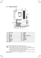
... 13) SPDIF_O 14) F_USB1/F_USB2/F_USB3 15) F_USB30 16) F_1394 17) CLR_CMOS 18) PHASE LED 19) TPM Read the following guidelines before turning on the motherboard. Hardware Installation - 22 -
... 13) SPDIF_O 14) F_USB1/F_USB2/F_USB3 15) F_USB30 16) F_1394 17) CLR_CMOS 18) PHASE LED 19) TPM Read the following guidelines before turning on the motherboard. Hardware Installation - 22 -
Manual
Page 23
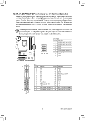
If the 12V power connector is turned off and all the components on the motherboard. 1/2) ATX_12V_2X4/ATX (2x4 12V Power Connector and 2x12 Main Power Connector) With the use of the power connector, the power supply can lead to an ...
If the 12V power connector is turned off and all the components on the motherboard. 1/2) ATX_12V_2X4/ATX (2x4 12V Power Connector and 2x12 Main Power Connector) With the use of the power connector, the power supply can lead to an ...


