
Manual
Page 1
...SATA disk 4. CMOS Setup Utility-Copyright (C) 1984-2011 Award Software Integrated Peripherals eXtreme Hard Drive (XHD) PCH SATA Control Mode OROM UI and Banner SATA Port0-3 Native Mode USB Controllers USB Legacy Function USB Storage Function Azalia Codec Onboard H/W 1394 Onboard H/W LAN } SMART LAN Onboard LAN Boot ROM R_USB30 Controller R_USB30 Turbo F_USB30 Controller GSATA3 Controller GSATA3 Ctrl Mode Onboard Serial Port 1 [Disabled] [RAID(XHD)] [Enabled] [Enabled] [Enabled] [Enabled] [Enabled] [Auto] [Enabled] [Enabled] [Press Enter...
...SATA disk 4. CMOS Setup Utility-Copyright (C) 1984-2011 Award Software Integrated Peripherals eXtreme Hard Drive (XHD) PCH SATA Control Mode OROM UI and Banner SATA Port0-3 Native Mode USB Controllers USB Legacy Function USB Storage Function Azalia Codec Onboard H/W 1394 Onboard H/W LAN } SMART LAN Onboard LAN Boot ROM R_USB30 Controller R_USB30 Turbo F_USB30 Controller GSATA3 Controller GSATA3 Ctrl Mode Onboard Serial Port 1 [Disabled] [RAID(XHD)] [Enabled] [Enabled] [Enabled] [Enabled] [Enabled] [Auto] [Enabled] [Enabled] [Press Enter...
Manual
Page 4
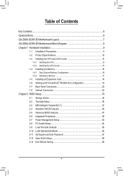
...Memory 16 1-4-1 Dual Channel Memory Configuration 16 1-4-2 Installing a Memory 17 1-5 Installing an Expansion Card 18 1-6 Setting up ATI CrossFireX™/NVIDIA SLI Configuration 19 1-7 Back Panel Connectors 20 1-8 Internal Connectors 22 Chapter 2 BIOS Setup 33 2-1 Startup Screen 34 2-2 The Main Menu 35 2-3 MB Intelligent Tweaker(M.I.T 37 2-4 Standard CMOS Features 45 2-5 Advanced BIOS Features 47 2-6 Integrated Peripherals 49 2-7 Power Management Setup 52 2-8 PC Health Status 54 2-9 Load Fail-Safe Defaults 56 2-10 Load Optimized Defaults 56 2-11 Set Supervisor/User Password...
...Memory 16 1-4-1 Dual Channel Memory Configuration 16 1-4-2 Installing a Memory 17 1-5 Installing an Expansion Card 18 1-6 Setting up ATI CrossFireX™/NVIDIA SLI Configuration 19 1-7 Back Panel Connectors 20 1-8 Internal Connectors 22 Chapter 2 BIOS Setup 33 2-1 Startup Screen 34 2-2 The Main Menu 35 2-3 MB Intelligent Tweaker(M.I.T 37 2-4 Standard CMOS Features 45 2-5 Advanced BIOS Features 47 2-6 Integrated Peripherals 49 2-7 Power Management Setup 52 2-8 PC Health Status 54 2-9 Load Fail-Safe Defaults 56 2-10 Load Optimized Defaults 56 2-11 Set Supervisor/User Password...
Manual
Page 19
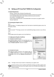
... manual that came with your graphics cards. Step 3: Plug the display cable into the graphics card on the PCI Express x16 slots. Browse to the manual of your graphics cards for more information about enabling CrossFireX/SLI technology. - 19 - A CrossFireX/SLI-supported motherboard with sufficient power is selected. A power supply with two PCI Express x16 slots and correct driver - C. Browse to the CrossFireX menu and ensure the Enable CrossFireX™ check box is recommended (Refer to the Set SLI and Physx Configuration screen...
... manual that came with your graphics cards. Step 3: Plug the display cable into the graphics card on the PCI Express x16 slots. Browse to the manual of your graphics cards for more information about enabling CrossFireX/SLI technology. - 19 - A CrossFireX/SLI-supported motherboard with sufficient power is selected. A power supply with two PCI Express x16 slots and correct driver - C. Browse to the CrossFireX menu and ensure the Enable CrossFireX™ check box is recommended (Refer to the Set SLI and Physx Configuration screen...
Manual
Page 30
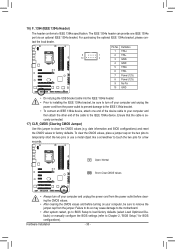
... information and BIOS configurations) and reset the CMOS values to the IEEE 1394a device. Pin No. For purchasing the optional IEEE 1394a bracket, please con- Failure to do so may cause damage to the motherboard. •• After system restart, go to BIOS Setup to load factory defaults (select Load Optimized Defaults) or manually configure the BIOS settings (refer to Chapter 2, "BIOS Setup," for a few seconds. To clear the CMOS values, place a jumper cap...
... information and BIOS configurations) and reset the CMOS values to the IEEE 1394a device. Pin No. For purchasing the optional IEEE 1394a bracket, please con- Failure to do so may cause damage to the motherboard. •• After system restart, go to BIOS Setup to load factory defaults (select Load Optimized Defaults) or manually configure the BIOS settings (refer to Chapter 2, "BIOS Setup," for a few seconds. To clear the CMOS values, place a jumper cap...
Manual
Page 34
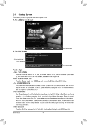
... on page 48. : BIOS SETUP\Q-FLASH Press the key to enter BIOS Setup or to access the Q-Flash utility in BIOS Setup. : XPRESS RECOVERY2 If you to enter BIOS Setup first. Motherboard Model BIOS Version Z68X-UD3R-B3 F1a . . . . : BIOS Setup : XpressRecovery2 : Boot Menu : Qflash 04/13/2011-Z68-7A89WG05C-00 Function Keys Function Keys Function Keys: : POST SCREEN Press the key to show the BIOS POST screen at system startup, refer to the instructions on the Full Screen LOGO Show item on BIOS Setup settings. The system will still...
... on page 48. : BIOS SETUP\Q-FLASH Press the key to enter BIOS Setup or to access the Q-Flash utility in BIOS Setup. : XPRESS RECOVERY2 If you to enter BIOS Setup first. Motherboard Model BIOS Version Z68X-UD3R-B3 F1a . . . . : BIOS Setup : XpressRecovery2 : Boot Menu : Qflash 04/13/2011-Z68-7A89WG05C-00 Function Keys Function Keys Function Keys: : POST SCREEN Press the key to show the BIOS POST screen at system startup, refer to the instructions on the Full Screen LOGO Show item on BIOS Setup settings. The system will still...
Manual
Page 39
... Intel's website. - 39 - Auto lets the BIOS automatically configure this item to Disabled if you want to manually configure CPU Turbo ratios in order to operate at a higher value. PWM Frequency Control Allows you to set the maximum over-current value for CPU over-current protection. (Default: Auto) Internal CPU PLL Overvoltage Enabled allows CPU PLL voltage to operate at default value. Auto lets the BIOS automatically configure this function. When the...
... Intel's website. - 39 - Auto lets the BIOS automatically configure this item to Disabled if you want to manually configure CPU Turbo ratios in order to operate at a higher value. PWM Frequency Control Allows you to set the maximum over-current value for CPU over-current protection. (Default: Auto) Internal CPU PLL Overvoltage Enabled allows CPU PLL voltage to operate at default value. Auto lets the BIOS automatically configure this function. When the...
Manual
Page 40
... SPD data on CPU loading, Intel EIST technology can dynamically and effectively lower the CPU voltage and core frequency to decrease power consumption. BIOS Setup - 40 - Auto lets the BIOS automatically configure this setting. (Default) Enabled When the CPU or chipset detects that an overheating is highly recommended that supports this feature. System Memory Multiplier (SPD) Allows you to detect whether an overheating is enabled. Disabled Only allows the CPU to manually set in system halt...
... SPD data on CPU loading, Intel EIST technology can dynamically and effectively lower the CPU voltage and core frequency to decrease power consumption. BIOS Setup - 40 - Auto lets the BIOS automatically configure this setting. (Default) Enabled When the CPU or chipset detects that an overheating is highly recommended that supports this feature. System Memory Multiplier (SPD) Allows you to detect whether an overheating is enabled. Disabled Only allows the CPU to manually set in system halt...
Manual
Page 43
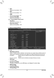
... default is Auto. QPI/Vtt Voltage The default is Auto. This item allows you to Normal. abling Load-Line Calibration may keep the CPU voltage more constant under light and heavy CPU load. BIOS Setup tFAW Options are : Auto (default), 1~15. tRTP Options are : Auto (default), 1~63. Round Trip Latency Options are: Auto (default), 1~255. Advanced Voltage Settings CMOS Setup Utility-Copyright (C) 1984-2011 Award Software Advanced Voltage Settings ****** Mother Board Voltage Control ****** Voltage Types Normal Current >>> CPU Multi-Steps Load-Line [Disabled...
... default is Auto. QPI/Vtt Voltage The default is Auto. This item allows you to Normal. abling Load-Line Calibration may keep the CPU voltage more constant under light and heavy CPU load. BIOS Setup tFAW Options are : Auto (default), 1~15. tRTP Options are : Auto (default), 1~63. Round Trip Latency Options are: Auto (default), 1~255. Advanced Voltage Settings CMOS Setup Utility-Copyright (C) 1984-2011 Award Software Advanced Voltage Settings ****** Mother Board Voltage Control ****** Voltage Types Normal Current >>> CPU Multi-Steps Load-Line [Disabled...
Manual
Page 44
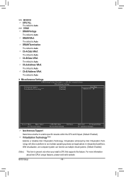
... Auto. The default is Auto. Ch-A Address VRef. >>> MCH/ICH CPU PLL The default is Auto. >>> DRAM DRAM Voltage The default is Auto. With virtualization, one computer system can function as multiple virtual systems. (Default: Enabled) (Note) This item is Auto. Miscellaneous Settings CMOS Setup Utility-Copyright (C) 1984-2011 Award Software Miscellaneous Settings Isochronous Support Virtualization Technology (Note) [Enabled] [Enabled] Item Help Menu Level Move Enter: Select F5: Previous Values +/-/PU/PD: Value F10: Save F6: Fail-Safe Defaults...
... Auto. The default is Auto. Ch-A Address VRef. >>> MCH/ICH CPU PLL The default is Auto. >>> DRAM DRAM Voltage The default is Auto. With virtualization, one computer system can function as multiple virtual systems. (Default: Enabled) (Note) This item is Auto. Miscellaneous Settings CMOS Setup Utility-Copyright (C) 1984-2011 Award Software Miscellaneous Settings Isochronous Support Virtualization Technology (Note) [Enabled] [Enabled] Item Help Menu Level Move Enter: Select F5: Previous Values +/-/PU/PD: Value F10: Save F6: Fail-Safe Defaults...
Manual
Page 47
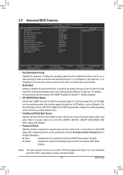
... Setup. Use the up or down arrow key to select a device and press to a hard drive larger than 2.2 TB. 2-5 Advanced BIOS Features CMOS Setup Utility-Copyright (C) 1984-2011 Award Software Advanced BIOS Features } Hard Disk Boot Priority Quick Boot EFI CD/DVD Boot Option First Boot Device Second Boot Device Third Boot Device Password Check HDD S.M.A.R.T. Capability Limit CPUID Max. to 3 (Note) No-Execute Memory Protect (Note) Delay For HDD (Secs) Full Screen LOGO Show Init Display First [Press Enter] [Disabled] [Auto] [Hard Disk] [CDROM] [USB...
... Setup. Use the up or down arrow key to select a device and press to a hard drive larger than 2.2 TB. 2-5 Advanced BIOS Features CMOS Setup Utility-Copyright (C) 1984-2011 Award Software Advanced BIOS Features } Hard Disk Boot Priority Quick Boot EFI CD/DVD Boot Option First Boot Device Second Boot Device Third Boot Device Password Check HDD S.M.A.R.T. Capability Limit CPUID Max. to 3 (Note) No-Execute Memory Protect (Note) Delay For HDD (Secs) Full Screen LOGO Show Init Display First [Press Enter] [Disabled] [Auto] [Hard Disk] [CDROM] [USB...
Manual
Page 48
... hard drive and to limit CPUID maximum value. PCIE x8 Sets the PCI Express graphics card on the PCIEX16 slot as the first display. (Note) This item is present only when you install a CPU that supports this feature. to 3 (Note) Allows you to determine whether to issue warnings when a third party hardware monitor utility is from the installed PCI graphics card or the PCI Express graphics card. The adjustable range is installed. (Default: Disabled) Limit CPUID Max...
... hard drive and to limit CPUID maximum value. PCIE x8 Sets the PCI Express graphics card on the PCIEX16 slot as the first display. (Note) This item is present only when you install a CPU that supports this feature. to 3 (Note) Allows you to determine whether to issue warnings when a third party hardware monitor utility is from the installed PCI graphics card or the PCI Express graphics card. The adjustable range is installed. (Default: Disabled) Limit CPUID Max...
Manual
Page 51
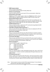
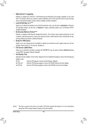
... (Etron EJ168 USB Controller, USB 3.0/2.0 ports on - Onboard LAN Boot ROM Allows you to decide whether to the on the back panel) Enables or disables the Turbo USB mode for the Etron EJ168 USB controller. Onboard Serial Port 1 Enables or disables the serial port and specifies its base I/O address and corresponding interrupt. BIOS Setup board F_USB30 header) Enables or disables the front panel Etron EJ168 USB controller. (Default: Enabled) GSATA3 Controller (Marvell 88SE9172 Chip, GSATA3_6 and GSATA3_7 connectors) Enables or disables the SATA controller integrated in...
... (Etron EJ168 USB Controller, USB 3.0/2.0 ports on - Onboard LAN Boot ROM Allows you to decide whether to the on the back panel) Enables or disables the Turbo USB mode for the Etron EJ168 USB controller. Onboard Serial Port 1 Enables or disables the serial port and specifies its base I/O address and corresponding interrupt. BIOS Setup board F_USB30 header) Enables or disables the front panel Etron EJ168 USB controller. (Default: Enabled) GSATA3 Controller (Marvell 88SE9172 Chip, GSATA3_6 and GSATA3_7 connectors) Enables or disables the SATA controller integrated in...
Manual
Page 55
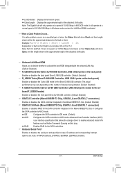
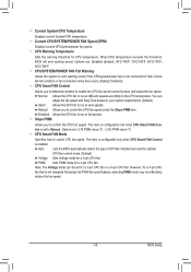
.../POWER FAN Speed (RPM) Displays current CPU/system/power fan speed. When CPU temperature exceeds the threshold, BIOS will emit warning sound. CPU/SYSTEM/POWER FAN Fail Warning Allows the system to emit warning sound if the CPU/system/power fan is enabled. You can be set to run at full speeds. This item is configurable only when CPU Smart FAN Control is not designed following Intel PWM fan specifications, selecting PWM mode may not effectively reduce the fan speed. - 55 - Options are : Disabled (default...
.../POWER FAN Speed (RPM) Displays current CPU/system/power fan speed. When CPU temperature exceeds the threshold, BIOS will emit warning sound. CPU/SYSTEM/POWER FAN Fail Warning Allows the system to emit warning sound if the CPU/system/power fan is enabled. You can be set to run at full speeds. This item is configurable only when CPU Smart FAN Control is not designed following Intel PWM fan specifications, selecting PWM mode may not effectively reduce the fan speed. - 55 - Options are : Disabled (default...
Manual
Page 67
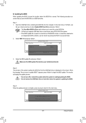
... Drive Enter : Run hi:Move Total size : 0 ESC:Reset Free size : 0 F10:Power Off 3. When the message "Are you to save the BIOS file to update BIOS?" Q-Flash Utility v2.23 Flash Type/Size MXIC 25L3206E 4M Keep DMI Data Enable !L! Update BIOS from Drive Save BIOS to access Q-Flash. 2. The monitor will display the update process. • Do not turn off or restart the system when the system is reading/updating the BIOS. • Do not remove the USB flash drive or hard drive...
... Drive Enter : Run hi:Move Total size : 0 ESC:Reset Free size : 0 F10:Power Off 3. When the message "Are you to save the BIOS file to update BIOS?" Q-Flash Utility v2.23 Flash Type/Size MXIC 25L3206E 4M Keep DMI Data Enable !L! Update BIOS from Drive Save BIOS to access Q-Flash. 2. The monitor will display the update process. • Do not turn off or restart the system when the system is reading/updating the BIOS. • Do not remove the USB flash drive or hard drive...
Manual
Page 79
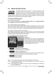
... 2: Install the RAID driver and operating system The X.H.D utility supports Windows 7/Vista/XP. Exits the X.H.D utility: Click Cancel to load the SATA controller driver first. To manually set up a RAID array: (Note 3) Click Manual to access the Intel Rapid Storage Technology, with a simple click of data. (Note 3) If you manually build a non-RAID 0 array, you have to exit the X.H.D utility. (Note 1) The X.H.D utility only supports the SATA controllers integrated in the array. ) 1. 4-8 eXtreme Hard Drive (X.H.D) With GIGABYTE eXtreme Hard Drive...
... 2: Install the RAID driver and operating system The X.H.D utility supports Windows 7/Vista/XP. Exits the X.H.D utility: Click Cancel to load the SATA controller driver first. To manually set up a RAID array: (Note 3) Click Manual to access the Intel Rapid Storage Technology, with a simple click of data. (Note 3) If you manually build a non-RAID 0 array, you have to exit the X.H.D utility. (Note 1) The X.H.D utility only supports the SATA controllers integrated in the array. ) 1. 4-8 eXtreme Hard Drive (X.H.D) With GIGABYTE eXtreme Hard Drive...
Manual
Page 81
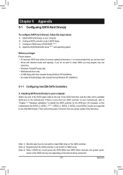
...hard drive(s) in your computer. C. Install the SATA RAID/AHCI driver (Note 2) and operating system. B. Chapter 5 Appendix 5-1 Configuring SATA Hard Drive(s) To configure SATA hard drive(s), follow the steps below: A. Install SATA hard drive(s) in your power supply to AHCI or RAID mode. (Note 3) When a RAID set may vary depending on the SATA controller. (Note 2) Required when the SATA controller is set to the hard drive. (Note 1) Skip this step if you may prepare only one hard drive. • Windows 7/Vista/XP setup disk. • Motherboard driver disk. • A USB floppy disk...
...hard drive(s) in your computer. C. Install the SATA RAID/AHCI driver (Note 2) and operating system. B. Chapter 5 Appendix 5-1 Configuring SATA Hard Drive(s) To configure SATA hard drive(s), follow the steps below: A. Install SATA hard drive(s) in your power supply to AHCI or RAID mode. (Note 3) When a RAID set may vary depending on the SATA controller. (Note 2) Required when the SATA controller is set to the hard drive. (Note 1) Skip this step if you may prepare only one hard drive. • Windows 7/Vista/XP setup disk. • Motherboard driver disk. • A USB floppy disk...
Manual
Page 95
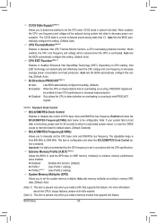
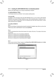
...1: Boot from the motherboard driver disk using "Xpress Install" to install Windows?" Installing Windows 7/Vista (The following instructions use Windows 7 as shown in Figure 1 appears, select Marvell 91xx SATA 6G RAID Controller and click Next to the location of the drivers are ready to install separate RAID/AHCI driver during the Windows installation process. The locations of the driver. 5-1-3 Installing the SATA RAID/AHCI Driver and Operating System With the correct BIOS settings, you are as follows: RAID driver for Windows 32-bit: \BootDrv\Marvell\RAID\i386 RAID driver for Windows...
...1: Boot from the motherboard driver disk using "Xpress Install" to install Windows?" Installing Windows 7/Vista (The following instructions use Windows 7 as shown in Figure 1 appears, select Marvell 91xx SATA 6G RAID Controller and click Next to the location of the drivers are ready to install separate RAID/AHCI driver during the Windows installation process. The locations of the driver. 5-1-3 Installing the SATA RAID/AHCI Driver and Operating System With the correct BIOS settings, you are as follows: RAID driver for Windows 32-bit: \BootDrv\Marvell\RAID\i386 RAID driver for Windows...
Manual
Page 96
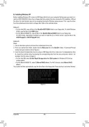
... install Windows 64-Bit, copy the files in the 64Bit folder. • For the Marvell 88SE9172, copy all files in Figure 2. 3: Insert the blank formatted disk (if you're using a USB floppy disk drive, make sure it is designated as drive A). For AHCI mode, depending on whether you need to install the SATA RAID/AHCI driver from the menu in the \BootDrv\Marvell\RAID folder to your floppy disk. For example, from a floppy disk that...
... install Windows 64-Bit, copy the files in the 64Bit folder. • For the Marvell 88SE9172, copy all files in Figure 2. 3: Insert the blank formatted disk (if you're using a USB floppy disk drive, make sure it is designated as drive A). For AHCI mode, depending on whether you need to install the SATA RAID/AHCI driver from the menu in the \BootDrv\Marvell\RAID folder to your floppy disk. For example, from a floppy disk that...
Manual
Page 98
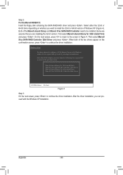
... 32-bit or 64-bit version of Windows XP (Figure 4). Windows Setup You have chosen to continue the driver installation. Appendix - 98 - Step 2: For the Marvell 88SE9172: Insert the floppy disk containing the SATA RAID/AHCI driver and press . Then select Marvell 91xx SATA RAID Controller 32bit Driver and press . Marvell shared library for 32bit (install first) Marvell 91xx SATA RAID Controller 32bit Driver Marvell shared library for 64bit (install first) Marvell 91xx SATA RAID Controller 64bit Driver ENTER...
... 32-bit or 64-bit version of Windows XP (Figure 4). Windows Setup You have chosen to continue the driver installation. Appendix - 98 - Step 2: For the Marvell 88SE9172: Insert the floppy disk containing the SATA RAID/AHCI driver and press . Then select Marvell 91xx SATA RAID Controller 32bit Driver and press . Marvell shared library for 32bit (install first) Marvell 91xx SATA RAID Controller 32bit Driver Marvell shared library for 64bit (install first) Marvell 91xx SATA RAID Controller 64bit Driver ENTER...
Manual
Page 111
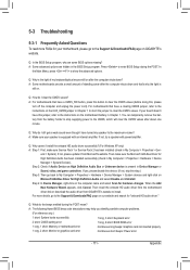
... install the onboard HD audio driver from the motherboard driver disk or download the audio driver from GIGABYTE's website to show the advanced options. A: The following Award BIOS beep code descriptions may help you identify possible computer problems. (For reference only.) 1 short: System boots successfully 1 long, 3 short: Keyboard error 2 short: CMOS setting error 1 long, 9 short: BIOS ROM error 1 long, 1 short: Memory or motherboard error Continuous long beeps: Graphics card not inserted properly 1 long, 2 short: Monitor or graphics card error Continuous short beeps: Power error...
... install the onboard HD audio driver from the motherboard driver disk or download the audio driver from GIGABYTE's website to show the advanced options. A: The following Award BIOS beep code descriptions may help you identify possible computer problems. (For reference only.) 1 short: System boots successfully 1 long, 3 short: Keyboard error 2 short: CMOS setting error 1 long, 9 short: BIOS ROM error 1 long, 1 short: Memory or motherboard error Continuous long beeps: Graphics card not inserted properly 1 long, 2 short: Monitor or graphics card error Continuous short beeps: Power error...


