
Manual
Page 1
...: Select F5: Previous Values +/-/PU/PD: Value F10: Save F6: Fail-Safe Defaults ESC: Exit F1: General Help F7: Optimized Defaults The BIOS Setup menus described here may differ from the exact settings for storing your motherboard. The maximum cache memory size is recommended that you have and... will see shall depend on the motherboard you have installed the operating system before enabling the Smart Response Technology. 1. Enabling RAID mode in BIOS Setup: Turn on the hard disk will be lost once you also need an SSD to the SATA disk 4. Installing the operating system...
...: Select F5: Previous Values +/-/PU/PD: Value F10: Save F6: Fail-Safe Defaults ESC: Exit F1: General Help F7: Optimized Defaults The BIOS Setup menus described here may differ from the exact settings for storing your motherboard. The maximum cache memory size is recommended that you have and... will see shall depend on the motherboard you have installed the operating system before enabling the Smart Response Technology. 1. Enabling RAID mode in BIOS Setup: Turn on the hard disk will be lost once you also need an SSD to the SATA disk 4. Installing the operating system...

Manual
Page 2
... enable the Intel Smart Response Technology: Step 1: After completing the steps above . 4. Installing the operating system and drivers to the SATA disk: After setting the BIOS, you can begin to install all motherboard drivers, including the Intel Rapid Storage Technology driver.
... enable the Intel Smart Response Technology: Step 1: After completing the steps above . 4. Installing the operating system and drivers to the SATA disk: After setting the BIOS, you can begin to install all motherboard drivers, including the Intel Rapid Storage Technology driver.
Manual
Page 3
... prior notice. For example, "REV: 1.0" means the revision of GIGABYTE. Copyright © 2011 GIGA-BYTE TECHNOLOGY CO., LTD. Changes to the specifications and features in the ...use of this product, GIGABYTE provides the following types of documentations: For quick set-up of this ...your motherboard looks like this manual is protected by GIGABYTE without GIGABYTE's prior written permission. For product-related information, check on our website at: http://www.gigabyte.com Identifying Your Motherboard Revision The revision number on...
... prior notice. For example, "REV: 1.0" means the revision of GIGABYTE. Copyright © 2011 GIGA-BYTE TECHNOLOGY CO., LTD. Changes to the specifications and features in the ...use of this product, GIGABYTE provides the following types of documentations: For quick set-up of this ...your motherboard looks like this manual is protected by GIGABYTE without GIGABYTE's prior written permission. For product-related information, check on our website at: http://www.gigabyte.com Identifying Your Motherboard Revision The revision number on...
Manual
Page 4
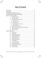
Table of Contents Box Contents...6 Optional Items...6 GA-Z68X-UD3R-B3 Motherboard Layout 7 GA-Z68X-UD3R-B3 Motherboard Block Diagram 8 Chapter 1 Hardware Installation 9 1-1 Installation Precautions 9 1-2 Product Specifications 10 1-3 Installing the CPU and CPU Cooler ... SLI Configuration 19 1-7 Back Panel Connectors 20 1-8 Internal Connectors 22 Chapter 2 BIOS Setup 33 2-1 Startup Screen 34 2-2 The Main Menu 35 2-3 MB Intelligent Tweaker(M.I.T 37 2-4 Standard CMOS Features 45 2-5 Advanced BIOS Features 47 2-6 Integrated Peripherals 49 2-7 Power Management Setup 52 2-8 PC Health ...
Table of Contents Box Contents...6 Optional Items...6 GA-Z68X-UD3R-B3 Motherboard Layout 7 GA-Z68X-UD3R-B3 Motherboard Block Diagram 8 Chapter 1 Hardware Installation 9 1-1 Installation Precautions 9 1-2 Product Specifications 10 1-3 Installing the CPU and CPU Cooler ... SLI Configuration 19 1-7 Back Panel Connectors 20 1-8 Internal Connectors 22 Chapter 2 BIOS Setup 33 2-1 Startup Screen 34 2-2 The Main Menu 35 2-3 MB Intelligent Tweaker(M.I.T 37 2-4 Standard CMOS Features 45 2-5 Advanced BIOS Features 47 2-6 Integrated Peripherals 49 2-7 Power Management Setup 52 2-8 PC Health ...
Manual
Page 5
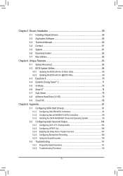
... 60 3-4 Contact...61 3-5 System...61 3-6 Download Center 62 3-7 New Utilities...62 Chapter 4 Unique Features 63 4-1 Xpress Recovery2 63 4-2 BIOS Update Utilities 66 4-2-1 Updating the BIOS with the Q-Flash Utility 66 4-2-2 Updating the BIOS with the @BIOS Utility 69 4-3 EasyTune 6...70 4-4 Dynamic Energy Saver™ 2 71 4-5 Q-Share...73 4-6 Smart 6™ ...74 4-7 Auto Green...78 4-8 eXtreme...
... 60 3-4 Contact...61 3-5 System...61 3-6 Download Center 62 3-7 New Utilities...62 Chapter 4 Unique Features 63 4-1 Xpress Recovery2 63 4-2 BIOS Update Utilities 66 4-2-1 Updating the BIOS with the Q-Flash Utility 66 4-2-2 Updating the BIOS with the @BIOS Utility 69 4-3 EasyTune 6...70 4-4 Dynamic Energy Saver™ 2 71 4-5 Q-Share...73 4-6 Smart 6™ ...74 4-7 Auto Green...78 4-8 eXtreme...
Manual
Page 8
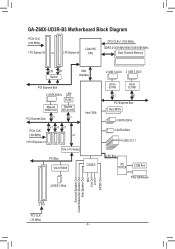
GA-Z68X-UD3R-B3 Motherboard Block Diagram PCIe CLK (100 MHz) 1 PCI Express x16 or 2 PCI Express x8 LGA1155 CPU CPU CLK+/- (100 MHz) DDR3 2133/1866/1600/1333/... to PCI Bridge Intel® Z68 PCI Bus VIA VT6308 CODEC 2 IEEE 1394a 2 USB 3.0/2.0 2 USB 3.0/2.0 Etron EJ168 Etron EJ168 x1 x1 PCI Express Bus Dual BIOS 4 SATA 3Gb/s 2 SATA 6Gb/s 14 USB 2.0/1.1 LPC Bus iTE IT8728 COM Port PS/2 KB/Mouse Surround Speaker Out Center/Subwoofer Speaker Out Side Speaker Out...
GA-Z68X-UD3R-B3 Motherboard Block Diagram PCIe CLK (100 MHz) 1 PCI Express x16 or 2 PCI Express x8 LGA1155 CPU CPU CLK+/- (100 MHz) DDR3 2133/1866/1600/1333/... to PCI Bridge Intel® Z68 PCI Bus VIA VT6308 CODEC 2 IEEE 1394a 2 USB 3.0/2.0 2 USB 3.0/2.0 Etron EJ168 Etron EJ168 x1 x1 PCI Express Bus Dual BIOS 4 SATA 3Gb/s 2 SATA 6Gb/s 14 USB 2.0/1.1 LPC Bus iTE IT8728 COM Port PS/2 KB/Mouse Surround Speaker Out Center/Subwoofer Speaker Out Side Speaker Out...
Manual
Page 12
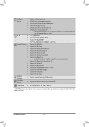
...flash ŠŠ Use of licensed AWARD BIOS ŠŠ Support for DualBIOS™ ŠŠ PnP 1.0a, DMI 2.0, SM BIOS 2.4, ACPI 1.0b Unique Features ŠŠ Support for @BIOS ŠŠ Support for Q-Flash ŠŠ Support for Xpress BIOS Rescue ŠŠ Support for Download Center...138; Support for Microsoft® Windows 7/Vista/XP Form Factor ŠŠ ATX Form Factor; 30.5cm x 24.4cm * GIGABYTE reserves the right to make any changes to the product specifications and product-related information without prior notice. Hardware ŠŠ System voltage...
...flash ŠŠ Use of licensed AWARD BIOS ŠŠ Support for DualBIOS™ ŠŠ PnP 1.0a, DMI 2.0, SM BIOS 2.4, ACPI 1.0b Unique Features ŠŠ Support for @BIOS ŠŠ Support for Q-Flash ŠŠ Support for Xpress BIOS Rescue ŠŠ Support for Download Center...138; Support for Microsoft® Windows 7/Vista/XP Form Factor ŠŠ ATX Form Factor; 30.5cm x 24.4cm * GIGABYTE reserves the right to make any changes to the product specifications and product-related information without prior notice. Hardware ŠŠ System voltage...
Manual
Page 16
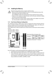
... - When enabling Dual Channel mode with two memory modules, we recommend that memory of the same capacity, brand, speed, and chips be used . (Go to GIGABYTE's website for optimum performance. DS/SS DDR3_3 - DS/SS DS/SS DDR3_1 DS/SS - DS/SS (SS=Single-Sided, DS=Double-Sided, "- -"=No Memory) DDR3_4... off the computer and unplug the power cord from the power outlet before installing the memory in only one DDR3 memory module is installed, the BIOS will double the original memory bandwidth. It is recommended that you install them in the DDR3_1 and DDR3_2 sockets.
... - When enabling Dual Channel mode with two memory modules, we recommend that memory of the same capacity, brand, speed, and chips be used . (Go to GIGABYTE's website for optimum performance. DS/SS DDR3_3 - DS/SS DS/SS DDR3_1 DS/SS - DS/SS (SS=Single-Sided, DS=Double-Sided, "- -"=No Memory) DDR3_4... off the computer and unplug the power cord from the power outlet before installing the memory in only one DDR3 memory module is installed, the BIOS will double the original memory bandwidth. It is recommended that you install them in the DDR3_1 and DDR3_2 sockets.
Manual
Page 18
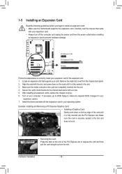
... expansion card. Hardware Installation - 18 - PCI Express x1 Slot PCI Express x16 Slot PCI Slot Follow the steps below to make any required BIOS changes for your expansion card(s). 777 Install the driver provided with the expansion card in your card. Carefully read the manual that supports your operating... chassis back panel with the slot, and press down on the card are completely inserted into the PCI Express slot. If necessary, go to BIOS Setup to correctly install your computer. Make sure the card is securely seated in the slot and does not rock. • Removing the Card...
... expansion card. Hardware Installation - 18 - PCI Express x1 Slot PCI Express x16 Slot PCI Slot Follow the steps below to make any required BIOS changes for your expansion card(s). 777 Install the driver provided with the expansion card in your card. Carefully read the manual that supports your operating... chassis back panel with the slot, and press down on the card are completely inserted into the PCI Express slot. If necessary, go to BIOS Setup to correctly install your computer. Make sure the card is securely seated in the slot and does not rock. • Removing the Card...
Manual
Page 24
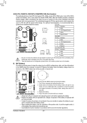
... headers possess a foolproof insertion design. Do not place a jumper cap on the headers. 6) BAT (Battery) The battery provides power to keep the values (such as BIOS configurations, date, and time information) in the CMOS when the computer is recommended that a system fan be handled in the power cord and restart your...
... headers possess a foolproof insertion design. Do not place a jumper cap on the headers. 6) BAT (Battery) The battery provides power to keep the values (such as BIOS configurations, date, and time information) in the CMOS when the computer is recommended that a system fan be handled in the power cord and restart your...
Manual
Page 27
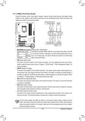
... the chassis front panel. One single short beep will be heard if no problem is detected, the BIOS may differ by issuing a beep code. When connecting your system using the power switch (refer to Chapter 2, "BIOS Setup," "Power Management Setup," for information about beep codes. •• HD (Hard Drive Activity LED...
... the chassis front panel. One single short beep will be heard if no problem is detected, the BIOS may differ by issuing a beep code. When connecting your system using the power switch (refer to Chapter 2, "BIOS Setup," "Power Management Setup," for information about beep codes. •• HD (Hard Drive Activity LED...
Manual
Page 28
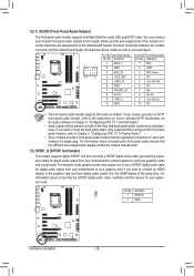
... 5 LINE2_R 4 NC 5 Line Out (R) 6 GND 6 NC 7 FAUDIO_JD 7 NC 8 No Pin 8 No Pin 9 LINE2_L 9 Line Out (L) 10 GND 10 NC DIP 1 23 1 DIP 1 23 1 DIP 1 23 1 BIOS Switcher (X58A-OC) DB_P•O•RTThe front panel audio header supports HD audio by expansionPcCaIerdposw)efrocrodnnigecittaorl(aSuATdAio)(Xo5u8Atp-OuCt)from the HDMI display at...
... 5 LINE2_R 4 NC 5 Line Out (R) 6 GND 6 NC 7 FAUDIO_JD 7 NC 8 No Pin 8 No Pin 9 LINE2_L 9 Line Out (L) 10 GND 10 NC DIP 1 23 1 DIP 1 23 1 DIP 1 23 1 BIOS Switcher (X58A-OC) DB_P•O•RTThe front panel audio header supports HD audio by expansionPcCaIerdposw)efrocrodnnigecittaorl(aSuATdAio)(Xo5u8Atp-OuCt)from the HDMI display at...
Manual
Page 29
... F_AUDIO(H) 20 11 Pin No. Definition 1 VBUS 11 D2+ 2 SSRX1- 12 D2- 3 SSRX1+ 13 GND 4 GND 14 SSTX2+ 5 SSTX1- 15 SSTX2- 6 SSTX1+ 16 GND DB_PORT BIOS 7 GND 17 SSRX2+ 8 D1- 18 SSRX2- 9 D1+ 19 VBUS 10 NC 20 No Pin When the system is in S4/S5 mode, only the USB...
... F_AUDIO(H) 20 11 Pin No. Definition 1 VBUS 11 D2+ 2 SSRX1- 12 D2- 3 SSRX1+ 13 GND 4 GND 14 SSTX2+ 5 SSTX1- 15 SSTX2- 6 SSTX1+ 16 GND DB_PORT BIOS 7 GND 17 SSRX2+ 8 D1- 18 SSRX2- 9 D1+ 19 VBUS 10 NC 20 No Pin When the system is in S4/S5 mode, only the USB...
Manual
Page 30
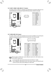
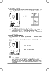
... CMOS values (e.g. tact the local dealer. Ensure that the cable is securely connected. 17) CLR_CMOS (Clearing CMOS Jumper) Use this jumper to Chapter 2, "BIOS Setup," for a few seconds. To clear the CMOS values, place a jumper cap on your computer, be sure to IEEE 1394a specification. Pin No. ...date information and BIOS configurations) and reset the CMOS values to touch the two pins for BIOS configurations). The IEEE 1394a header can provide one end of the device cable to your computer and then ...
... CMOS values (e.g. tact the local dealer. Ensure that the cable is securely connected. 17) CLR_CMOS (Clearing CMOS Jumper) Use this jumper to Chapter 2, "BIOS Setup," for a few seconds. To clear the CMOS values, place a jumper cap on your computer, be sure to IEEE 1394a specification. Pin No. ...date information and BIOS configurations) and reset the CMOS values to touch the two pins for BIOS configurations). The IEEE 1394a header can provide one end of the device cable to your computer and then ...
Manual
Page 31
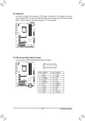
...™ 2," for more the number of lighted LEDs indicates the CPU loading. 18) PHASE LED The number of lighted LEDs. Refer to this header. DB_PORT BIOS Switc 1 1 19 TPM w/housing 20 Pin No. 1 2 3 4 5 6 7 8 9 10 Definition LCLK GND LFRAME No Pin LRESET NC LAD3 LAD2 VCC3 LAD1 1 Voltage measurement module(X58A-OC...
...™ 2," for more the number of lighted LEDs indicates the CPU loading. 18) PHASE LED The number of lighted LEDs. Refer to this header. DB_PORT BIOS Switc 1 1 19 TPM w/housing 20 Pin No. 1 2 3 4 5 6 7 8 9 10 Definition LCLK GND LFRAME No Pin LRESET NC LAD3 LAD2 VCC3 LAD1 1 Voltage measurement module(X58A-OC...
Manual
Page 33
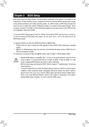
... BIOS, use either the GIGABYTE Q-Flash or @BIOS utility. • Q-Flash allows the user to quickly and easily upgrade or back up BIOS without entering the operating system. • @BIOS is turned on using the Q-Flash and @BIOS utilities, refer to Chapter 4, "BIOS Update Utilities." • Because BIOS flashing...need to) to prevent system instability or other unexpected results. BIOS includes a BIOS Setup program that searches and downloads the latest version of BIOS from the Internet and updates the BIOS. To access the BIOS Setup program, press the key during the POST when the power...
... BIOS, use either the GIGABYTE Q-Flash or @BIOS utility. • Q-Flash allows the user to quickly and easily upgrade or back up BIOS without entering the operating system. • @BIOS is turned on using the Q-Flash and @BIOS utilities, refer to Chapter 4, "BIOS Update Utilities." • Because BIOS flashing...need to) to prevent system instability or other unexpected results. BIOS includes a BIOS Setup program that searches and downloads the latest version of BIOS from the Internet and updates the BIOS. To access the BIOS Setup program, press the key during the POST when the power...
Manual
Page 34
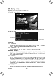
...LOGO Screen (Default) B. To exit Boot Menu, press . Motherboard Model BIOS Version Z68X-UD3R-B3 F1a . . . . : BIOS Setup : XpressRecovery2 : Boot Menu : Qflash 04/13/2011-Z68-7A89WG05C...appear when the computer boots. A. You can be used for one time only. To show the BIOS POST screen. After system restart, the device boot order will directly boot from the device configured in ... is effective for subsequent access to the instructions on the Full Screen LOGO Show item on BIOS Setup settings. BIOS Setup - 34 - In Boot Menu, use the up hard drive data using the driver...
...LOGO Screen (Default) B. To exit Boot Menu, press . Motherboard Model BIOS Version Z68X-UD3R-B3 F1a . . . . : BIOS Setup : XpressRecovery2 : Boot Menu : Qflash 04/13/2011-Z68-7A89WG05C...appear when the computer boots. A. You can be used for one time only. To show the BIOS POST screen. After system restart, the device boot order will directly boot from the device configured in ... is effective for subsequent access to the instructions on the Full Screen LOGO Show item on BIOS Setup settings. BIOS Setup - 34 - In Boot Menu, use the up hard drive data using the driver...
Manual
Page 35
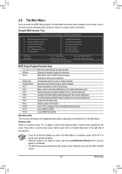
... more advanced options. • When the system is displayed on the screen. Help for each item is in this chapter are for the menu. BIOS Setup Submenu Help While in a submenu, press to exit the help screen (General Help) of the function keys Move cursor to the Item Help ...& Exit Setup Exit Without Saving ESC: Quit F8: Q-Flash Select Item F10: Save & Exit Setup Change CPU's Clock & Voltage F11: Save CMOS to BIOS F12: Load CMOS from BIOS BIOS Setup Program Function Keys Move the selection bar to select an item Execute command or enter the submenu Main Menu: Exit the...
... more advanced options. • When the system is displayed on the screen. Help for each item is in this chapter are for the menu. BIOS Setup Submenu Help While in a submenu, press to exit the help screen (General Help) of the function keys Move cursor to the Item Help ...& Exit Setup Exit Without Saving ESC: Quit F8: Q-Flash Select Item F10: Save & Exit Setup Change CPU's Clock & Voltage F11: Save CMOS to BIOS F12: Load CMOS from BIOS BIOS Setup Program Function Keys Move the selection bar to select an item Execute command or enter the submenu Main Menu: Exit the...
Manual
Page 36
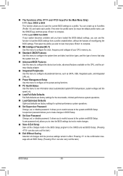
.... F12: Load CMOS from a profile created before, without the hassles of errors that stop the system boot, etc. Advanced BIOS Features Use this menu to configure the device boot order, advanced features available on the CPU, and the primary display adapter. Integrated Peripherals ... Change, set , or disable password. First enter the profile name (to erase the default profile name, use this function to load the BIOS settings from BIOS If your CPU, memory, etc. Standard CMOS Features Use this menu to configure the system time and date, hard drive types,...
.... F12: Load CMOS from a profile created before, without the hassles of errors that stop the system boot, etc. Advanced BIOS Features Use this menu to configure the device boot order, advanced features available on the CPU, and the primary display adapter. Integrated Peripherals ... Change, set , or disable password. First enter the profile name (to erase the default profile name, use this function to load the BIOS settings from BIOS If your CPU, memory, etc. Standard CMOS Features Use this menu to configure the system time and date, hard drive types,...
Manual
Page 37
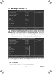
...Miscellaneous Settings [Press Enter] [Press Enter] [Press Enter] [Press Enter] [Press Enter] Item Help Menu Level BIOS Version BCLK CPU Frequency Memory Frequency Total Memory Size CPU Temperature Vcore DRAM Voltage F1a 99.80 MHz 3193.85 MHz 1330.... Settings [Press Enter] [Press Enter] [Press Enter] [Press Enter] [Press Enter] Item Help Menu Level BIOS Version BCLK CPU Frequency Memory Frequency Total Memory Size CPU Temperature Vcore DRAM Voltage F1a 99.80 MHz 3193.85 MHz 1330....
...Miscellaneous Settings [Press Enter] [Press Enter] [Press Enter] [Press Enter] [Press Enter] Item Help Menu Level BIOS Version BCLK CPU Frequency Memory Frequency Total Memory Size CPU Temperature Vcore DRAM Voltage F1a 99.80 MHz 3193.85 MHz 1330.... Settings [Press Enter] [Press Enter] [Press Enter] [Press Enter] [Press Enter] Item Help Menu Level BIOS Version BCLK CPU Frequency Memory Frequency Total Memory Size CPU Temperature Vcore DRAM Voltage F1a 99.80 MHz 3193.85 MHz 1330....


