Manual
Page 1
GA-X38T-DQ6 LGA775 socket motherboard for Intel® CoreTM processor family/ Intel® Pentium® processor family/Intel® Celeron® processor family User's Manual Rev. 1002 12ME-X38TDQ6-1002R
GA-X38T-DQ6 LGA775 socket motherboard for Intel® CoreTM processor family/ Intel® Pentium® processor family/Intel® Celeron® processor family User's Manual Rev. 1002 12ME-X38TDQ6-1002R
Manual
Page 2
Motherboard GA-X38T-DQ6 Sept. 7, 2007 Motherboard GA-X38T-DQ6 Sept. 7, 2007
Motherboard GA-X38T-DQ6 Sept. 7, 2007 Motherboard GA-X38T-DQ6 Sept. 7, 2007
Manual
Page 3
.... Example: For product-related information, check on our website at: http://www.gigabyte.com.tw Identifying Your Motherboard Revision The revision number on our website. Check your motherboard looks like this manual may be reproduced, copied, translated, transmitted, or published in... to their respective owners. Disclaimer Information in the use of this product, GIGABYTE provides the following types of documentations: „ For quick set-up of GIGABYTE branded motherboards. Documentation Classifications In order to assist in this manual may be made by...
.... Example: For product-related information, check on our website at: http://www.gigabyte.com.tw Identifying Your Motherboard Revision The revision number on our website. Check your motherboard looks like this manual may be reproduced, copied, translated, transmitted, or published in... to their respective owners. Disclaimer Information in the use of this product, GIGABYTE provides the following types of documentations: „ For quick set-up of GIGABYTE branded motherboards. Documentation Classifications In order to assist in this manual may be made by...
Manual
Page 4
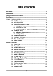
Table of Contents Box Contents ...6 OptionalItems ...6 GA-X38T-DQ6 Motherboard Layout 7 Block Diagram ...8 Chapter 1 Hardware Installation 9 1-1 Installation Precautions 9 1-2 Product Specifications 10 1-3 Installing the CPU and CPU Cooler 13 1-3-1 Installing the CPU 13 1-3-2 Installing the CPU Cooler 15 1-3-3 Removing the Crazy Cool Heatsink from the Back of the Motherboard ..... 16 1-4 Installing the Memory 17 1-4-1 Dual Channel Memory...
Table of Contents Box Contents ...6 OptionalItems ...6 GA-X38T-DQ6 Motherboard Layout 7 Block Diagram ...8 Chapter 1 Hardware Installation 9 1-1 Installation Precautions 9 1-2 Product Specifications 10 1-3 Installing the CPU and CPU Cooler 13 1-3-1 Installing the CPU 13 1-3-2 Installing the CPU Cooler 15 1-3-3 Removing the Crazy Cool Heatsink from the Back of the Motherboard ..... 16 1-4 Installing the Memory 17 1-4-1 Dual Channel Memory...
Manual
Page 6
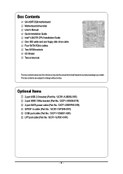
The box contents are for reference only and the actual items shall depend on product package you obtain. Box Contents GA-X38T-DQ6 motherboard Motherboard driver disk User's Manual Quick Installation Guide Intel® LGA775 CPU Installation Guide One IDE cable and one floppy disk drive cable Four SATA 3Gb/s ...
The box contents are for reference only and the actual items shall depend on product package you obtain. Box Contents GA-X38T-DQ6 motherboard Motherboard driver disk User's Manual Quick Installation Guide Intel® LGA775 CPU Installation Guide One IDE cable and one floppy disk drive cable Four SATA 3Gb/s ...
Manual
Page 7
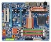
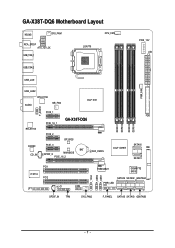
GA-X38T-DQ6 Motherboard Layout KB_MS SYS_FAN1 RCA_SPDIF ATX_12V_2X USB_1394_1 LGA775 CPU_FAN PCIE_12V ATX USB_1394_2 USB_LAN PWR_FAN USB_LAN2 RTL8111B AUDIO NB_FAN Intel® X38 F_AUDIO RTL8111B CODEC CD_IN PCIE_1 PCIE_16_1 GA-X38T-DQ6 PCIE_2 BP_BIOS PCIE_3 BAT SPDIF_O MAIN BIOS PCIE_16_2 CLR_CMOS FDD DDRIII1 DDRIII2 DDRIII3 DDRIII4 Intel® ICH9R SATAII0 IDE SATAII1 PCI1 IT8718 PCI2 CI COM LPT F_1394 F_USB2 F_USB1 TSB43AB23 GIGABYTE SATA2 SATAII4 SATAII2 GSATAIIA PWR_LED SPDIF_IN TPM SYS_FAN2 F_PANEL SATAII5 SATAII3 GSATAIIB - 7 -
GA-X38T-DQ6 Motherboard Layout KB_MS SYS_FAN1 RCA_SPDIF ATX_12V_2X USB_1394_1 LGA775 CPU_FAN PCIE_12V ATX USB_1394_2 USB_LAN PWR_FAN USB_LAN2 RTL8111B AUDIO NB_FAN Intel® X38 F_AUDIO RTL8111B CODEC CD_IN PCIE_1 PCIE_16_1 GA-X38T-DQ6 PCIE_2 BP_BIOS PCIE_3 BAT SPDIF_O MAIN BIOS PCIE_16_2 CLR_CMOS FDD DDRIII1 DDRIII2 DDRIII3 DDRIII4 Intel® ICH9R SATAII0 IDE SATAII1 PCI1 IT8718 PCI2 CI COM LPT F_1394 F_USB2 F_USB1 TSB43AB23 GIGABYTE SATA2 SATAII4 SATAII2 GSATAIIA PWR_LED SPDIF_IN TPM SYS_FAN2 F_PANEL SATAII5 SATAII3 GSATAIIB - 7 -
Manual
Page 9
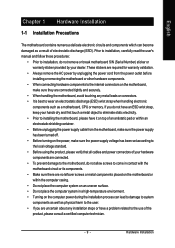
... components to the internal connectors on the power, make sure they are connected tightly and securely. • When handling the motherboard, avoid touching any metal leads or connectors. • It is best to wear an electrostatic discharge (ESD) wrist strap when... of the product, please consult a certified computer technician. - 9 - Hardware Installation English Chapter 1 Hardware Installation 1-1 Installation Precautions The motherboard contains numerous delicate electronic circuits and components which can lead to damage to system components as well as physical harm to the user. &#...
... components to the internal connectors on the power, make sure they are connected tightly and securely. • When handling the motherboard, avoid touching any metal leads or connectors. • It is best to wear an electrostatic discharge (ESD) wrist strap when... of the product, please consult a certified computer technician. - 9 - Hardware Installation English Chapter 1 Hardware Installation 1-1 Installation Precautions The motherboard contains numerous delicate electronic circuits and components which can lead to damage to system components as well as physical harm to the user. &#...
Manual
Page 10
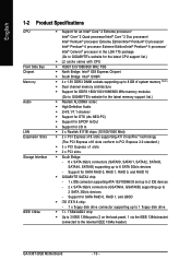
...of system memory (Note1) Š Dual channel memory architecture Š Support for DDR3 1600/1333/1066/800 MHz memory modules (Go to GIGABYTE's website for the latest memory support list.) Š Realtek ALC889A codec Š High Definition Audio Š 2/4/5.1/7.1-channel Š Support for ...JBOD Š iTE IT8718 chip: - 1 x floppy disk drive connector supporting up to the internal IEEE 1394a header) GA-X38T-DQ6 Motherboard - 10 - Support for SATA RAID 0, RAID 1, RAID 5, and RAID 10 Š GIGABYTE SATA2 chip: - 1 x IDE connector supporting ATA-133/100/66/33 and up to 2 IDE devices - 2 x...
...of system memory (Note1) Š Dual channel memory architecture Š Support for DDR3 1600/1333/1066/800 MHz memory modules (Go to GIGABYTE's website for the latest memory support list.) Š Realtek ALC889A codec Š High Definition Audio Š 2/4/5.1/7.1-channel Š Support for ...JBOD Š iTE IT8718 chip: - 1 x floppy disk drive connector supporting up to the internal IEEE 1394a header) GA-X38T-DQ6 Motherboard - 10 - Support for SATA RAID 0, RAID 1, RAID 5, and RAID 10 Š GIGABYTE SATA2 chip: - 1 x IDE connector supporting ATA-133/100/66/33 and up to 2 IDE devices - 2 x...
Manual
Page 12
.... (Note 4) Due to chipset limitation, Intel ICH9R RAID driver does not support Windows 2000 operating system. Adjust DDR3 frequency - Increase FSB voltage by 0.05V to : - GA-X38T-DQ6 Motherboard - 12 - Adjust CPU host frequency from 90 MHz to 150 MHz with 0.025V increment Š Frequency adjustments in BIOS Setup (CPU/DDR3/PCI-E) allow you...
.... (Note 4) Due to chipset limitation, Intel ICH9R RAID driver does not support Windows 2000 operating system. Adjust DDR3 frequency - Increase FSB voltage by 0.05V to : - GA-X38T-DQ6 Motherboard - 12 - Adjust CPU host frequency from 90 MHz to 150 MHz with 0.025V increment Š Frequency adjustments in BIOS Setup (CPU/DDR3/PCI-E) allow you...
Manual
Page 13
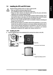
...of the CPU. • Do not turn off the computer and unplug the power cord from the power outlet before installing the CPU to GIGABYTE's website for the peripherals. Hardware Installation LGA775 CPU Socket Alignment Key LGA 775 CPU Alignment Key Pin One Corner of the CPU Socket Notch...the CPU. It is not installed, otherwise overheating and damage of the CPU. Locate the alignment keys on the motherboard CPU socket and the notches on the CPU - 13 - mended that the motherboard supports the CPU. (Go to prevent hardware damage. • Locate the pin one of the CPU may ...
...of the CPU. • Do not turn off the computer and unplug the power cord from the power outlet before installing the CPU to GIGABYTE's website for the peripherals. Hardware Installation LGA775 CPU Socket Alignment Key LGA 775 CPU Alignment Key Pin One Corner of the CPU Socket Notch...the CPU. It is not installed, otherwise overheating and damage of the CPU. Locate the alignment keys on the motherboard CPU socket and the notches on the CPU - 13 - mended that the motherboard supports the CPU. (Go to prevent hardware damage. • Locate the pin one of the CPU may ...
Manual
Page 14
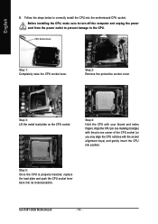
Step 3: Lift the metal load plate on the CPU socket. GA-X38T-DQ6 Motherboard - 14 - Before installing the CPU, make sure to turn off the computer and unplug the power cord from the power outlet to prevent damage to correctly install the CPU into the motherboard CPU socket. Step 4: Hold the CPU with the socket alignment...
Step 3: Lift the metal load plate on the CPU socket. GA-X38T-DQ6 Motherboard - 14 - Before installing the CPU, make sure to turn off the computer and unplug the power cord from the power outlet to prevent damage to correctly install the CPU into the motherboard CPU socket. Step 4: Hold the CPU with the socket alignment...
Manual
Page 15
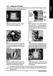
...installed CPU. Check that the Male and Female push pins are joined closely. (Refer to your CPU cooler installation manual for instructions on the motherboard. If the push pin is inserted as the example cooler.) Step 1: Apply an even and thin layer of thermal grease on the surface ...of the motherboard. English 1-3-2 Installing the CPU Cooler Follow the steps below to correctly install the CPU cooler on the motherboard. (The following procedure uses Intel® boxed cooler as the picture above, the installation is...
...installed CPU. Check that the Male and Female push pins are joined closely. (Refer to your CPU cooler installation manual for instructions on the motherboard. If the push pin is inserted as the example cooler.) Step 1: Apply an even and thin layer of thermal grease on the surface ...of the motherboard. English 1-3-2 Installing the CPU Cooler Follow the steps below to correctly install the CPU cooler on the motherboard. (The following procedure uses Intel® boxed cooler as the picture above, the installation is...
Manual
Page 16
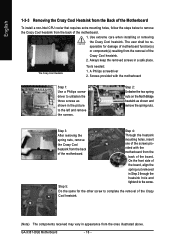
...shall be responsible for the other screw to complete the removal of the motherboard. The Crazy Cool Heatsink Tools needed: 1. On the front side of the board. Screws provided with the motherboard from the ones illustrated above. Step 2: Unfasten the two spring nuts on...the screw. Through the heatsink mounting holes, insert one of the screws provided with the motherboard Step 1: Use a Philips screwdriver to unfasten the three screws as shown and remove the spring nuts. GA-X38T-DQ6 Motherboard - 16 - Use extreme care when installing or removing the Crazy Cool heatsink. A ...
...shall be responsible for the other screw to complete the removal of the motherboard. The Crazy Cool Heatsink Tools needed: 1. On the front side of the board. Screws provided with the motherboard from the ones illustrated above. Step 2: Unfasten the two spring nuts on...the screw. Through the heatsink mounting holes, insert one of the screws provided with the motherboard Step 1: Use a Philips screwdriver to unfasten the three screws as shown and remove the spring nuts. GA-X38T-DQ6 Motherboard - 16 - Use extreme care when installing or removing the Crazy Cool heatsink. A ...
Manual
Page 17
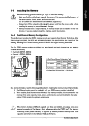
... following guidelines before you are unable to insert the memory, switch the direction. 1-4-1 Dual Channel Memory Configuration This motherboard provides four DDR3 memory sockets and supports Dual Channel Technology. DS/SS - - Four Modules DS/SS DS/SS... DS/SS DDRIII4 - After the memory is recommended that the motherboard supports the memory. DS/SS DS/SS (SS=Single-Sided, DS=Double-Sided, "- -"=No Memory) DDRIII1 DDRIII2... mode. 1. A memory module can be used . (Go to GIGABYTE's website for optimum performance. Hardware Installation
... following guidelines before you are unable to insert the memory, switch the direction. 1-4-1 Dual Channel Memory Configuration This motherboard provides four DDR3 memory sockets and supports Dual Channel Technology. DS/SS - - Four Modules DS/SS DS/SS... DS/SS DDRIII4 - After the memory is recommended that the motherboard supports the memory. DS/SS DS/SS (SS=Single-Sided, DS=Double-Sided, "- -"=No Memory) DDRIII1 DDRIII2... mode. 1. A memory module can be used . (Go to GIGABYTE's website for optimum performance. Hardware Installation
Manual
Page 18
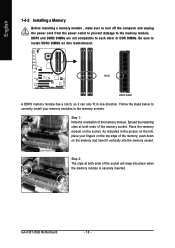
...memory module on the left, place your memory modules in the picture on the socket. Step 2: The clips at both ends of the memory module. GA-X38T-DQ6 Motherboard - 18 - DDR3 and DDR2 DIMMs are not compatible to each other or DDR DIMMs. Be sure to correctly install your fingers on the top ...edge of the memory socket. Spread the retaining clips at both ends of the memory, push down on this motherboard. Step 1: Note the orientation of the socket will snap into the memory socket. As indicated in the memory sockets. Notch DDR3 DIMM A DDR3 memory...
...memory module on the left, place your memory modules in the picture on the socket. Step 2: The clips at both ends of the memory module. GA-X38T-DQ6 Motherboard - 18 - DDR3 and DDR2 DIMMs are not compatible to each other or DDR DIMMs. Be sure to correctly install your fingers on the top ...edge of the memory socket. Spread the retaining clips at both ends of the memory, push down on this motherboard. Step 1: Note the orientation of the socket will snap into the memory socket. As indicated in the memory sockets. Notch DDR3 DIMM A DDR3 memory...
Manual
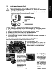
Page 19
... in your operating system. Install the driver provided with a screw. 5. When you begin to install an expansion card: • Make sure the motherboard supports the expansion card. PCI Express x16 Slot PCI Express x1 Slot PCI Slot Follow the steps below to correctly install your power supply to... the Card: Pull out the small whitedrawable bar at the end of the white-drawable bar to release the card. - 19 - • The motherboard provides a PCIE_12V power connector, which can also press the latch on your expansion card. • Always turn off the computer and unplug the power cord...
... in your operating system. Install the driver provided with a screw. 5. When you begin to install an expansion card: • Make sure the motherboard supports the expansion card. PCI Express x16 Slot PCI Express x1 Slot PCI Slot Follow the steps below to correctly install your power supply to... the Card: Pull out the small whitedrawable bar at the end of the white-drawable bar to release the card. - 19 - • The motherboard provides a PCIE_12V power connector, which can also press the latch on your expansion card. • Always turn off the computer and unplug the power cord...
Manual
Page 20
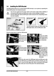
... power switch on the bracket. Then attach the SATA power cable to the power connector on your motherboard. Step 2: Connect the SATA cable from the bracket SATA signal cable into the corresponding connectors when installing. GA-X38T-DQ6 Motherboard - 20 - SATA Bracket SATA Signal Cable SATA Power Cable External SATA Connector Power Connector External SATA...
... power switch on the bracket. Then attach the SATA power cable to the power connector on your motherboard. Step 2: Connect the SATA cable from the bracket SATA signal cable into the corresponding connectors when installing. GA-X38T-DQ6 Motherboard - 20 - SATA Bracket SATA Signal Cable SATA Power Cable External SATA Connector Power Connector External SATA...
Manual
Page 21
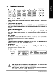
... digital optical audio. Before using this port for an IEEE 1394a device. Use this feature, ensure that your device and then remove it from the motherboard. • When removing the cable, pull it side to side to 1 Gbps data rate. Do not rock it straight out from the connector. English 1-7 Back...
... digital optical audio. Before using this port for an IEEE 1394a device. Use this feature, ensure that your device and then remove it from the motherboard. • When removing the cable, pull it side to side to 1 Gbps data rate. Do not rock it straight out from the connector. English 1-7 Back...
Manual
Page 22
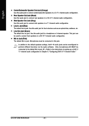
... default speakers settings, the ~ audio jacks can be connected to connect rear speakers in devices such as an optical drive, walkman, etc. Use this jack. GA-X38T-DQ6 Motherboard - 22 - Microphones must be used to perform different functions via the audio software. Rear Speaker Out Jack (Black) Use this audio jack to this audio...
... default speakers settings, the ~ audio jacks can be connected to connect rear speakers in devices such as an optical drive, walkman, etc. Use this jack. GA-X38T-DQ6 Motherboard - 22 - Microphones must be used to perform different functions via the audio software. Rear Speaker Out Jack (Black) Use this audio jack to this audio...
Manual
Page 23
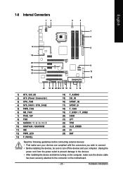
... 18) F_1394 19) F_USB1 / F_USB2 20) COM 21) LPT 22) TPM 23) CLR_CMOS 24) CI 25) BAT Read the following guidelines before turning on the motherboard. - 23 - Hardware Installation Unplug the power cord from the power outlet to prevent damage to the devices. • After installing the device and before connecting...
... 18) F_1394 19) F_USB1 / F_USB2 20) COM 21) LPT 22) TPM 23) CLR_CMOS 24) CI 25) BAT Read the following guidelines before turning on the motherboard. - 23 - Hardware Installation Unplug the power cord from the power outlet to prevent damage to the devices. • After installing the device and before connecting...


