
Manual
Page 1
... 1) The X.H.D utility only supports the SATA controllers integrated in the array. ) 1. Or you run the X.H.D utility, back up all motherboard drivers, including the X.H.D utility. Without the driver, the hard drive may not be able to set up a RAID-ready system and configure...0 array. 2. A. The following procedure details the steps to automatically set up a RAID 0 array later using the Auto function. Using GIGABYTE eXtreme Hard Drive (X.H.D) Instructions:(Note 2) Before launching X.H.D, make sure the new drive is recommended that already exists, users also can go to...
... 1) The X.H.D utility only supports the SATA controllers integrated in the array. ) 1. Or you run the X.H.D utility, back up all motherboard drivers, including the X.H.D utility. Without the driver, the hard drive may not be able to set up a RAID-ready system and configure...0 array. 2. A. The following procedure details the steps to automatically set up a RAID 0 array later using the Auto function. Using GIGABYTE eXtreme Hard Drive (X.H.D) Instructions:(Note 2) Before launching X.H.D, make sure the new drive is recommended that already exists, users also can go to...
Manual
Page 1
GA-Q57M-S2H LGA1156 socket motherboard for Intel® Core™ i7 processor family/ Intel® Core™ i5 processor family/ Intel® Core™ i3 processor family User's Manual Rev. 1002 12ME-Q57MS2H-1002R
GA-Q57M-S2H LGA1156 socket motherboard for Intel® Core™ i7 processor family/ Intel® Core™ i5 processor family/ Intel® Core™ i3 processor family User's Manual Rev. 1002 12ME-Q57MS2H-1002R
Manual
Page 2
Motherboard GA-Q57M-S2H Mar. 8, 2010 Motherboard GA-Q57M-S2H Mar. 8, 2010
Motherboard GA-Q57M-S2H Mar. 8, 2010 Motherboard GA-Q57M-S2H Mar. 8, 2010
Manual
Page 3
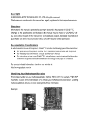
... or download the information on/from the Support&Downloads\Motherboard\Technology Guide page on our website. For product-related information, check on our website at: http://www.gigabyte.com.tw Identifying Your Motherboard Revision The revision number on how to the specifications and... may be reproduced, copied, translated, transmitted, or published in the use GIGABYTE's unique features, read the User's Manual. For instructions on your motherboard revision before updating motherboard BIOS, drivers, or when looking for technical information. Disclaimer Information in this...
... or download the information on/from the Support&Downloads\Motherboard\Technology Guide page on our website. For product-related information, check on our website at: http://www.gigabyte.com.tw Identifying Your Motherboard Revision The revision number on how to the specifications and... may be reproduced, copied, translated, transmitted, or published in the use GIGABYTE's unique features, read the User's Manual. For instructions on your motherboard revision before updating motherboard BIOS, drivers, or when looking for technical information. Disclaimer Information in this...
Manual
Page 4
Table of Contents Box Contents...6 Optional Items...6 GA-Q57M-S2H Motherboard Layout 7 GA-Q57M-S2H Motherboard Block Diagram 8 Chapter 1 Hardware Installation 9 1-1 Installation Precautions 9 1-2 Product Specifications 10 1-3 Installing the CPU and CPU Cooler 13 1-3-1 Installing the CPU 13 1-3-2 Installing the CPU Cooler ...
Table of Contents Box Contents...6 Optional Items...6 GA-Q57M-S2H Motherboard Layout 7 GA-Q57M-S2H Motherboard Block Diagram 8 Chapter 1 Hardware Installation 9 1-1 Installation Precautions 9 1-2 Product Specifications 10 1-3 Installing the CPU and CPU Cooler 13 1-3-1 Installing the CPU 13 1-3-2 Installing the CPU Cooler ...
Manual
Page 6
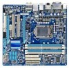
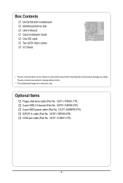
...Part No. 12CF1-2SERPW-0*R) S/PDIF In cable (Part No. 12CR1-1SPDIN-0*R) COM port cable (Part No. 12CF1-1CM001-3*R) - 6 - Box Contents GA-Q57M-S2H motherboard Motherboard driver disk User's Manual Quick Installation Guide One IDE cable Two SATA 3Gb/s cables I/O Shield • The box contents above are subject to change ...without notice. • The motherboard image is for reference only and the actual items shall depend on the product package you obtain. The box contents are for reference only...
...Part No. 12CF1-2SERPW-0*R) S/PDIF In cable (Part No. 12CR1-1SPDIN-0*R) COM port cable (Part No. 12CF1-1CM001-3*R) - 6 - Box Contents GA-Q57M-S2H motherboard Motherboard driver disk User's Manual Quick Installation Guide One IDE cable Two SATA 3Gb/s cables I/O Shield • The box contents above are subject to change ...without notice. • The motherboard image is for reference only and the actual items shall depend on the product package you obtain. The box contents are for reference only...
Manual
Page 7
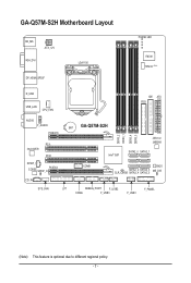
GA-Q57M-S2H Motherboard Layout KB_MS ATX_12V VGA_DVI DP_HDMI_SPDIF LGA1156 PHASE LED IT8720 TPM IC (Note) R_USB USB_LAN CPU_FAN IDE ATX FDD AUDIO F_AUDIO PCIEX16 PCI1 Intel 82578 PCI2 SPDIF_I CODEC SPDIF_O PCIEX4 CD_IN BAT GA-Q57M-S2H Intel® Q57 DDR3_2 DDR3_1 DDR3_4 DDR3_3 JMicron JMB368 SATA2_0 SATA2_1 COMB BIOS SATA2_2 SATA2_3 CLR_CMOS SATA2_4 SATA2_5 ME_DIS SYS_FAN LPT DEBUG_PORT F_USB2 F_PANEL COMA F_USB3 F_USB1 (Note) This feature is optional due to different regional policy. - 7 -
GA-Q57M-S2H Motherboard Layout KB_MS ATX_12V VGA_DVI DP_HDMI_SPDIF LGA1156 PHASE LED IT8720 TPM IC (Note) R_USB USB_LAN CPU_FAN IDE ATX FDD AUDIO F_AUDIO PCIEX16 PCI1 Intel 82578 PCI2 SPDIF_I CODEC SPDIF_O PCIEX4 CD_IN BAT GA-Q57M-S2H Intel® Q57 DDR3_2 DDR3_1 DDR3_4 DDR3_3 JMicron JMB368 SATA2_0 SATA2_1 COMB BIOS SATA2_2 SATA2_3 CLR_CMOS SATA2_4 SATA2_5 ME_DIS SYS_FAN LPT DEBUG_PORT F_USB2 F_PANEL COMA F_USB3 F_USB1 (Note) This feature is optional due to different regional policy. - 7 -
Manual
Page 8
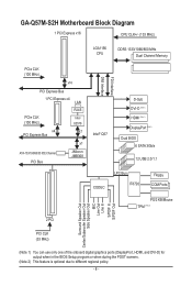
GA-Q57M-S2H Motherboard Block Diagram 1 PCI Express x16 CPU CLK+/- (133 MHz) LGA1156 CPU DDR3 1333/1066/800 MHz Dual Channel Memory PCIe CLK (100 MHz) x16 PCI ...
GA-Q57M-S2H Motherboard Block Diagram 1 PCI Express x16 CPU CLK+/- (133 MHz) LGA1156 CPU DDR3 1333/1066/800 MHz Dual Channel Memory PCIe CLK (100 MHz) x16 PCI ...
Manual
Page 9
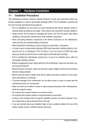
...an electrostatic shielding container. • Before unplugging the power supply cable from the power outlet before installing or removing the motherboard or other hardware components. • When connecting hardware components to the internal connectors on the computer power during the ...installation process can become damaged as a result of the product, please consult a certified computer technician. - 9 - ponents such as a motherboard, CPU or memory. These stickers are required for warranty validation. • Always remove the AC power by your dealer. Chapter 1 Hardware ...
...an electrostatic shielding container. • Before unplugging the power supply cable from the power outlet before installing or removing the motherboard or other hardware components. • When connecting hardware components to the internal connectors on the computer power during the ...installation process can become damaged as a result of the product, please consult a certified computer technician. - 9 - ponents such as a motherboard, CPU or memory. These stickers are required for warranty validation. • Always remove the AC power by your dealer. Chapter 1 Hardware ...
Manual
Page 12
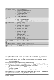
... will depend on the CPU cooler you must install an Intel CPU with integrated graphics. (Note 3) The DVI-D port does not support D-Sub connection by motherboard model.
... will depend on the CPU cooler you must install an Intel CPU with integrated graphics. (Note 3) The DVI-D port does not support D-Sub connection by motherboard model.
Manual
Page 13
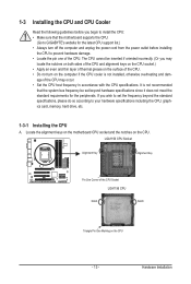
...according to your hardware specifications including the CPU, graphics card, memory, hard drive, etc. 1-3-1 Installing the CPU A. Locate the alignment keys on the motherboard CPU socket and the notches on the CPU - 13 - It is not installed, otherwise overheating and dam- The CPU cannot be set the frequency ...for the latest CPU support list.) • Always turn on the computer if the CPU cooler is not recommended that the motherboard supports the CPU. (Go to GIGABYTE's website for the peripherals. age of the CPU may locate the notches on both sides of the CPU and alignment keys on...
...according to your hardware specifications including the CPU, graphics card, memory, hard drive, etc. 1-3-1 Installing the CPU A. Locate the alignment keys on the motherboard CPU socket and the notches on the CPU - 13 - It is not installed, otherwise overheating and dam- The CPU cannot be set the frequency ...for the latest CPU support list.) • Always turn on the computer if the CPU cooler is not recommended that the motherboard supports the CPU. (Go to GIGABYTE's website for the peripherals. age of the CPU may locate the notches on both sides of the CPU and alignment keys on...
Manual
Page 14
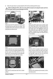
... properly inserted, use one corner of the socket cover and use the other to the CPU. Step 5: Push the CPU socket lever back into the motherboard CPU socket. Then completely lift the CPU socket lever and the metal load plate will be lifted as shown. Step 1: Gently press the CPU socket...
... properly inserted, use one corner of the socket cover and use the other to the CPU. Step 5: Push the CPU socket lever back into the motherboard CPU socket. Then completely lift the CPU socket lever and the metal load plate will be lifted as shown. Step 1: Gently press the CPU socket...
Manual
Page 15
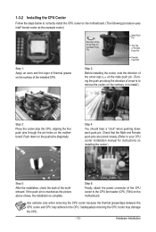
...pin. (Turning the push pin along the direction of arrow is to remove the cooler, on the motherboard. If the push pin is inserted as the example cooler.) Direction of the Arrow Sign on the ...grease on installing the cooler.) Step 5: After the installation, check the back of the motherboard. Push down each push pin. 1-3-2 Installing the CPU Cooler Follow the steps below to correctly install the ...CPU cooler on the motherboard. (The following procedure uses Intel® boxed cooler as the picture above shows, the ...
...pin. (Turning the push pin along the direction of arrow is to remove the cooler, on the motherboard. If the push pin is inserted as the example cooler.) Direction of the Arrow Sign on the ...grease on installing the cooler.) Step 5: After the installation, check the back of the motherboard. Push down each push pin. 1-3-2 Installing the CPU Cooler Follow the steps below to correctly install the ...CPU cooler on the motherboard. (The following procedure uses Intel® boxed cooler as the picture above shows, the ...
Manual
Page 16
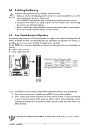
...mode will automatically detect the specifications and capacity of the same capacity, brand, speed, and chips be used . (Go to GIGABYTE's website for optimum performance. If only one direction. 1-4 Installing the Memory Read the following guidelines before you are divided into ..., "- -"=No Memory) DDR3_2 DDR3_1 DDR3_4 DDR3_3 Due to insert the memory, switch the direction. 1-4-1 Dual Channel Memory Configuration This motherboard provides four DDR3 memory sockets and supports Dual Channel Technology. When enabling Dual Channel mode with two memory modules, be enabled if only...
...mode will automatically detect the specifications and capacity of the same capacity, brand, speed, and chips be used . (Go to GIGABYTE's website for optimum performance. If only one direction. 1-4 Installing the Memory Read the following guidelines before you are divided into ..., "- -"=No Memory) DDR3_2 DDR3_1 DDR3_4 DDR3_3 Due to insert the memory, switch the direction. 1-4-1 Dual Channel Memory Configuration This motherboard provides four DDR3 memory sockets and supports Dual Channel Technology. When enabling Dual Channel mode with two memory modules, be enabled if only...
Manual
Page 17
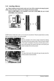
..., make sure to turn off the computer and unplug the power cord from the power outlet to prevent damage to install DDR3 DIMMs on this motherboard. Step 2: The clips at both ends of the memory socket. Follow the steps below to correctly install your fingers on the socket. Place the memory...
..., make sure to turn off the computer and unplug the power cord from the power outlet to prevent damage to install DDR3 DIMMs on this motherboard. Step 2: The clips at both ends of the memory socket. Follow the steps below to correctly install your fingers on the socket. Place the memory...
Manual
Page 18
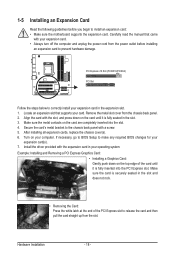
... turn off the computer and unplug the power cord from the power outlet before you begin to install an expansion card: • Make sure the motherboard supports the expansion card. 1-5 Installing an Expansion Card Read the following guidelines before installing an expansion card to prevent hardware damage. Make sure the metal...
... turn off the computer and unplug the power cord from the power outlet before you begin to install an expansion card: • Make sure the motherboard supports the expansion card. 1-5 Installing an Expansion Card Read the following guidelines before installing an expansion card to prevent hardware damage. Make sure the metal...
Manual
Page 21
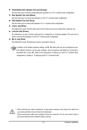
... speakers settings, the ~ audio jacks can be connected to a back panel connector, first remove the cable from your device and then remove it from the motherboard. • When removing the cable, pull it side to side to connect rear speakers in a 4/5.1/7.1-channel audio configuration. This jack can be connected to this...
... speakers settings, the ~ audio jacks can be connected to a back panel connector, first remove the cable from your device and then remove it from the motherboard. • When removing the cable, pull it side to side to connect rear speakers in a 4/5.1/7.1-channel audio configuration. This jack can be connected to this...
Manual
Page 22
..., make sure your devices are compliant with the connectors you wish to connect. • Before installing the devices, be sure to the connector on the motherboard. Unplug the power cord from the power outlet to prevent damage to the devices. • After installing the device and before connecting external devices: •...
..., make sure your devices are compliant with the connectors you wish to connect. • Before installing the devices, be sure to the connector on the motherboard. Unplug the power cord from the power outlet to prevent damage to the devices. • After installing the device and before connecting external devices: •...
Manual
Page 23
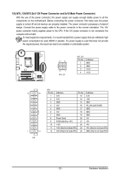
... is used that can withstand high power consumption be used (500W or greater). If a power supply is turned off and all the components on the motherboard.
... is used that can withstand high power consumption be used (500W or greater). If a power supply is turned off and all the components on the motherboard.
Manual
Page 24
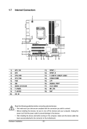
...4 Speed Control SYS_FAN: 1 Pin No. Overheating may result in the correct orientation (the black connector wire is typically designated by a stripe of different color. The motherboard supports CPU fan speed control, which requires the use of the cable is the ground wire). CPU_FAN: 1 Pin No. Definition SYS_FAN 1 GND 2 +12V / ... Connector) This connector is recommended that a system fan be sure to prevent your CPU and system from overheating. 3/4) CPU_FAN/SYS_FAN (Fan Headers) The motherboard has a 4-pin CPU fan header (CPU_FAN) and a 4-pin system fan header (SYS_FAN).
...4 Speed Control SYS_FAN: 1 Pin No. Overheating may result in the correct orientation (the black connector wire is typically designated by a stripe of different color. The motherboard supports CPU fan speed control, which requires the use of the cable is the ground wire). CPU_FAN: 1 Pin No. Definition SYS_FAN 1 GND 2 +12V / ... Connector) This connector is recommended that a system fan be sure to prevent your CPU and system from overheating. 3/4) CPU_FAN/SYS_FAN (Fan Headers) The motherboard has a 4-pin CPU fan header (CPU_FAN) and a 4-pin system fan header (SYS_FAN).


