
Manual
Page 1
... set up a RAID 0 array later using the Auto function. A. Setting Up a RAID-Ready System Step 1: Configure the system BIOS Enter the system BIOS Setup program, set up a RAID 0 array: Click Auto to automatically and quickly set eXtreme Hard Drive (X.H.D) under the Integrated Peripherals...insert the motherboard driver disk. Step 2: Install the RAID driver and operating system The X.H.D utility supports Windows 7/Vista/XP. Using GIGABYTE eXtreme Hard Drive (X.H.D) Instructions:(Note 2) Before launching X.H.D, make sure the newly added harddrive has equal or greater capacity than or...
... set up a RAID 0 array later using the Auto function. A. Setting Up a RAID-Ready System Step 1: Configure the system BIOS Enter the system BIOS Setup program, set up a RAID 0 array: Click Auto to automatically and quickly set eXtreme Hard Drive (X.H.D) under the Integrated Peripherals...insert the motherboard driver disk. Step 2: Install the RAID driver and operating system The X.H.D utility supports Windows 7/Vista/XP. Using GIGABYTE eXtreme Hard Drive (X.H.D) Instructions:(Note 2) Before launching X.H.D, make sure the newly added harddrive has equal or greater capacity than or...
Manual
Page 3
... to the specifications and features in the use GIGABYTE's unique features, read or download the information on/from the Support&Downloads\Motherboard\Technology Guide page on your motherboard revision before updating motherboard BIOS, drivers, or when looking for technical information.... Check your motherboard looks like this manual may be made by any form or by GIGABYTE without GIGABYTE's prior written permission. All rights reserved. Changes to...
... to the specifications and features in the use GIGABYTE's unique features, read or download the information on/from the Support&Downloads\Motherboard\Technology Guide page on your motherboard revision before updating motherboard BIOS, drivers, or when looking for technical information.... Check your motherboard looks like this manual may be made by any form or by GIGABYTE without GIGABYTE's prior written permission. All rights reserved. Changes to...
Manual
Page 4
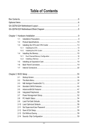
Table of Contents Box Contents...6 Optional Items...6 GA-Q57M-S2H Motherboard Layout 7 GA-Q57M-S2H Motherboard Block Diagram 8 Chapter 1 Hardware Installation 9 1-1 Installation Precautions 9 1-2 Product Specifications 10 1-3 Installing the CPU and CPU ... an Expansion Card 18 1-6 Back Panel Connectors 19 1-7 Internal Connectors 22 Chapter 2 BIOS Setup 33 2-1 Startup Screen 34 2-2 The Main Menu 35 2-3 MB Intelligent Tweaker(M.I.T 37 2-4 Standard CMOS Features 45 2-5 Advanced BIOS Features 47 2-6 Integrated Peripherals 50 2-7 Power Management Setup 52 2-8 PC Health Status ...
Table of Contents Box Contents...6 Optional Items...6 GA-Q57M-S2H Motherboard Layout 7 GA-Q57M-S2H Motherboard Block Diagram 8 Chapter 1 Hardware Installation 9 1-1 Installation Precautions 9 1-2 Product Specifications 10 1-3 Installing the CPU and CPU ... an Expansion Card 18 1-6 Back Panel Connectors 19 1-7 Internal Connectors 22 Chapter 2 BIOS Setup 33 2-1 Startup Screen 34 2-2 The Main Menu 35 2-3 MB Intelligent Tweaker(M.I.T 37 2-4 Standard CMOS Features 45 2-5 Advanced BIOS Features 47 2-6 Integrated Peripherals 50 2-7 Power Management Setup 52 2-8 PC Health Status ...
Manual
Page 5
... 62 3-4 Contact...63 3-5 System...63 3-6 Download Center 64 3-7 New Utilities...64 Chapter 4 Unique Features 65 4-1 Xpress Recovery2 65 4-2 BIOS Update Utilities 68 4-2-1 Updating the BIOS with the Q-Flash Utility 68 4-2-2 Updating the BIOS with the @BIOS Utility 71 4-3 EasyTune 6...72 4-4 Q-Share...73 4-5 SMART Recovery 74 4-6 Smart TPM 75 4-7 Auto Green...76 4-8 eXtreme Hard Drive...
... 62 3-4 Contact...63 3-5 System...63 3-6 Download Center 64 3-7 New Utilities...64 Chapter 4 Unique Features 65 4-1 Xpress Recovery2 65 4-2 BIOS Update Utilities 68 4-2-1 Updating the BIOS with the Q-Flash Utility 68 4-2-2 Updating the BIOS with the @BIOS Utility 71 4-3 EasyTune 6...72 4-4 Q-Share...73 4-5 SMART Recovery 74 4-6 Smart TPM 75 4-7 Auto Green...76 4-8 eXtreme Hard Drive...
Manual
Page 7
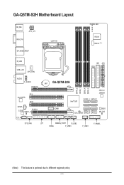
GA-Q57M-S2H Motherboard Layout KB_MS ATX_12V VGA_DVI DP_HDMI_SPDIF LGA1156 PHASE LED IT8720 TPM IC (Note) R_USB USB_LAN CPU_FAN IDE ATX FDD AUDIO F_AUDIO PCIEX16 PCI1 Intel 82578 PCI2 SPDIF_I CODEC SPDIF_O PCIEX4 CD_IN BAT GA-Q57M-S2H Intel® Q57 DDR3_2 DDR3_1 DDR3_4 DDR3_3 JMicron JMB368 SATA2_0 SATA2_1 COMB BIOS SATA2_2 SATA2_3 CLR_CMOS SATA2_4 SATA2_5 ME_DIS SYS_FAN LPT DEBUG_PORT F_USB2 F_PANEL COMA F_USB3 F_USB1 (Note) This feature is optional due to different regional policy. - 7 -
GA-Q57M-S2H Motherboard Layout KB_MS ATX_12V VGA_DVI DP_HDMI_SPDIF LGA1156 PHASE LED IT8720 TPM IC (Note) R_USB USB_LAN CPU_FAN IDE ATX FDD AUDIO F_AUDIO PCIEX16 PCI1 Intel 82578 PCI2 SPDIF_I CODEC SPDIF_O PCIEX4 CD_IN BAT GA-Q57M-S2H Intel® Q57 DDR3_2 DDR3_1 DDR3_4 DDR3_3 JMicron JMB368 SATA2_0 SATA2_1 COMB BIOS SATA2_2 SATA2_3 CLR_CMOS SATA2_4 SATA2_5 ME_DIS SYS_FAN LPT DEBUG_PORT F_USB2 F_PANEL COMA F_USB3 F_USB1 (Note) This feature is optional due to different regional policy. - 7 -
Manual
Page 8
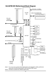
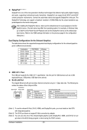
GA-Q57M-S2H Motherboard Block Diagram 1 PCI Express x16 CPU CLK+/- (133 MHz) LGA1156 CPU DDR3 1333/1066/...PCI Bus JMicron JMB368 FDI Interface DMI Interface Intel® Q57 D-Sub DVI-D (Note 1) HDMI (Note 1) DisplayPort (Note 1) Dual BIOS 6 SATA 3Gb/s 12 USB 2.0/1.1 CODEC LPC Bus IT8720 Floppy COM Ports PS/2 KB/Mouse TPM (Note 2) Surround Speaker Out Center/...only one of the onboard digital graphics ports (DisplayPort, HDMI, and DVI-D) for output when in the BIOS Setup program or when during the POST screens. (Note 2) This feature is optional due to different regional policy. - 8 -
GA-Q57M-S2H Motherboard Block Diagram 1 PCI Express x16 CPU CLK+/- (133 MHz) LGA1156 CPU DDR3 1333/1066/...PCI Bus JMicron JMB368 FDI Interface DMI Interface Intel® Q57 D-Sub DVI-D (Note 1) HDMI (Note 1) DisplayPort (Note 1) Dual BIOS 6 SATA 3Gb/s 12 USB 2.0/1.1 CODEC LPC Bus IT8720 Floppy COM Ports PS/2 KB/Mouse TPM (Note 2) Surround Speaker Out Center/...only one of the onboard digital graphics ports (DisplayPort, HDMI, and DVI-D) for output when in the BIOS Setup program or when during the POST screens. (Note 2) This feature is optional due to different regional policy. - 8 -
Manual
Page 12
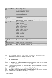
...fan fail warning CPU fan speed control (Note 7) 1 x 64 Mbit flash Use of licensed AWARD BIOS PnP 1.0a, DMI 2.0, SM BIOS 2.4, ACPI 1.0b Support for @BIOS Support for Q-Flash Support for Xpress BIOS Rescue Support for Download Center Support for Xpress Install Support for Xpress Recovery2 Support for EasyTune (Note ... Drive Support for Q-Share Support for Smart Recovery Norton Internet Security (OEM version) Operating System w Support for out- put when in the BIOS Setup program or when during the POST screens. (Note 5) For optimum performance, if only one PCI Express graphics card is to x4 mode...
...fan fail warning CPU fan speed control (Note 7) 1 x 64 Mbit flash Use of licensed AWARD BIOS PnP 1.0a, DMI 2.0, SM BIOS 2.4, ACPI 1.0b Support for @BIOS Support for Q-Flash Support for Xpress BIOS Rescue Support for Download Center Support for Xpress Install Support for Xpress Recovery2 Support for EasyTune (Note ... Drive Support for Q-Share Support for Smart Recovery Norton Internet Security (OEM version) Operating System w Support for out- put when in the BIOS Setup program or when during the POST screens. (Note 5) For optimum performance, if only one PCI Express graphics card is to x4 mode...
Manual
Page 16
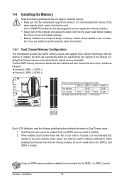
... brand, speed, and chips be used . (Go to install the memory: • Make sure that the motherboard supports the memory. If you begin to GIGABYTE's website for optimum performance. DS/SS Four Modules DS/SS DS/SS DS/SS DS/SS (SS=Single-Sided, DS=Double-Sided, "- -"=No Memory) ...DDR3_2 DDR3_1 DDR3_4 DDR3_3 Due to install them in only one DDR3 memory module is installed, the BIOS will double the original memory bandwidth. When enabling Dual Channel mode with two memory modules, be used for the latest supported memory speeds and memory...
... brand, speed, and chips be used . (Go to install the memory: • Make sure that the motherboard supports the memory. If you begin to GIGABYTE's website for optimum performance. DS/SS Four Modules DS/SS DS/SS DS/SS DS/SS (SS=Single-Sided, DS=Double-Sided, "- -"=No Memory) ...DDR3_2 DDR3_1 DDR3_4 DDR3_3 Due to install them in only one DDR3 memory module is installed, the BIOS will double the original memory bandwidth. When enabling Dual Channel mode with two memory modules, be used for the latest supported memory speeds and memory...
Manual
Page 18
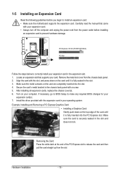
Remove the metal slot cover from the slot. If necessary, go to BIOS Setup to correctly install your expansion card(s). 7. Turn on the card are completely inserted into the PCI Express slot. Make sure the card is securely ... card until it is fully inserted into the slot. 4. PCI Express x16 Slot (PCIEX16/PCIEX4) PCI Slot Follow the steps below to make any required BIOS changes for your expansion card in the slot and does not rock. • Removing the Card: Press the white latch at the end of the...
Remove the metal slot cover from the slot. If necessary, go to BIOS Setup to correctly install your expansion card(s). 7. Turn on the card are completely inserted into the PCI Express slot. Make sure the card is securely ... card until it is fully inserted into the slot. 4. PCI Express x16 Slot (PCIEX16/PCIEX4) PCI Slot Follow the steps below to make any required BIOS changes for your expansion card in the slot and does not rock. • Removing the Card: Press the white latch at the end of the...
Manual
Page 20
... of the LAN port LEDs. put when in Windows Vista, go to this port for USB devices such as the default playback device. Combination POST/BIOS Windows DVI-D + D-Sub Yes Yes DVI-D + HDMI No Yes DVI-D + DP No Yes HDMI + D-Sub Yes Yes HDMI + DP No .... DiplayPort(Note 1)(Note 3) DisplayPort is one of the onboard digital graphics ports (DisplayPort, HDMI, and DVI-D) for out- For example, in the BIOS Setup program or when during the POST screens. Use this port. The following de- Hardware Installation - 20 - Connection/ Speed LED Activity LED Speed ...
... of the LAN port LEDs. put when in Windows Vista, go to this port for USB devices such as the default playback device. Combination POST/BIOS Windows DVI-D + D-Sub Yes Yes DVI-D + HDMI No Yes DVI-D + DP No Yes HDMI + D-Sub Yes Yes HDMI + DP No .... DiplayPort(Note 1)(Note 3) DisplayPort is one of the onboard digital graphics ports (DisplayPort, HDMI, and DVI-D) for out- For example, in the BIOS Setup program or when during the POST screens. Use this port. The following de- Hardware Installation - 20 - Connection/ Speed LED Activity LED Speed ...
Manual
Page 26
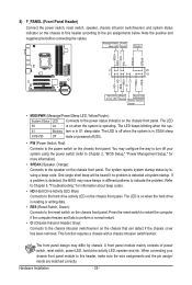
...): Connects to the power status indicator on the chassis front panel. Hardware Installation - 26 - The LED is off when the system is detected, the BIOS may differ by issuing a beep code. A front panel module mainly consists of power switch, reset switch, power LED, hard drive activity LED, speaker ...panel module to the power switch on the chassis front panel. When connecting your system using the power switch (refer to Chapter 2, "BIOS Setup," "Power Management Setup," for information about beep codes. • HD (Hard Drive Activity LED, Blue) Connects to indicate the problem.
...): Connects to the power status indicator on the chassis front panel. Hardware Installation - 26 - The LED is off when the system is detected, the BIOS may differ by issuing a beep code. A front panel module mainly consists of power switch, reset switch, power LED, hard drive activity LED, speaker ...panel module to the power switch on the chassis front panel. When connecting your system using the power switch (refer to Chapter 2, "BIOS Setup," "Power Management Setup," for information about beep codes. • HD (Hard Drive Activity LED, Blue) Connects to indicate the problem.
Manual
Page 31
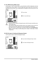
... damage to the motherboard. • After system restart, go to BIOS Setup to load factory defaults (select Load Optimized Defaults) or manually configure the BIOS settings (refer to Chapter 2, "BIOS Setup," for BIOS configurations). 18) ME_DIS (Jumper for a few seconds. date information and BIOS configurations) and reset the CMOS values to enable or disable Intel...
... damage to the motherboard. • After system restart, go to BIOS Setup to load factory defaults (select Load Optimized Defaults) or manually configure the BIOS settings (refer to Chapter 2, "BIOS Setup," for BIOS configurations). 18) ME_DIS (Jumper for a few seconds. date information and BIOS configurations) and reset the CMOS values to enable or disable Intel...
Manual
Page 32
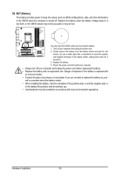
Replace the battery. 4. Hardware Installation - 32 - 19) BAT (Battery) The battery provides power to keep the values (such as BIOS configurations, date, and time information) in the CMOS when the computer is replaced with an incorrect model. • Contact the place of purchase or local ...
Replace the battery. 4. Hardware Installation - 32 - 19) BAT (Battery) The battery provides power to keep the values (such as BIOS configurations, date, and time information) in the CMOS when the computer is replaced with an incorrect model. • Contact the place of purchase or local ...
Manual
Page 33
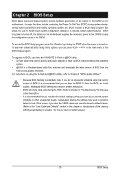
...to prevent system instability or other unexpected results. Chapter 2 BIOS Setup BIOS (Basic Input and Output System) records hardware parameters of the BIOS Setup program. BIOS includes a BIOS Setup program that you not flash the BIOS. To see more advanced BIOS Setup menu options, you need to) to clear the ...-On Self-Test (POST) during system startup, saving system parameters and loading operating system, etc. To upgrade the BIOS, use either the GIGABYTE Q-Flash or @BIOS utility. • Q-Flash allows the user to the "Load Optimized Defaults" section in system's failure to activate ...
...to prevent system instability or other unexpected results. Chapter 2 BIOS Setup BIOS (Basic Input and Output System) records hardware parameters of the BIOS Setup program. BIOS includes a BIOS Setup program that you not flash the BIOS. To see more advanced BIOS Setup menu options, you need to) to clear the ...-On Self-Test (POST) during system startup, saving system parameters and loading operating system, etc. To upgrade the BIOS, use either the GIGABYTE Q-Flash or @BIOS utility. • Q-Flash allows the user to the "Load Optimized Defaults" section in system's failure to activate ...
Manual
Page 34
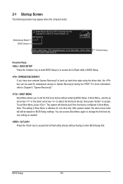
...access the Q-Flash utility directly without entering BIOS Setup. To exit Boot Menu, press . You can be based on BIOS Setup settings. 2-1 Startup Screen The following screens may appear when the computer boots. BIOS Setup - 34 - Q57M-S2H F4 . . . . : BIOS Setup : XpressRecovery2 : Boot Menu : ...Qflash 03/01/2010-Q57-7A89TG0HC-00 Function Keys Function Keys: : BIOS SETUP Press the key to enter BIOS Setup or to access the Q-Flash utility ...
...access the Q-Flash utility directly without entering BIOS Setup. To exit Boot Menu, press . You can be based on BIOS Setup settings. 2-1 Startup Screen The following screens may appear when the computer boots. BIOS Setup - 34 - Q57M-S2H F4 . . . . : BIOS Setup : XpressRecovery2 : Boot Menu : ...Qflash 03/01/2010-Q57-7A89TG0HC-00 Function Keys Function Keys: : BIOS SETUP Press the key to enter BIOS Setup or to access the Q-Flash utility ...
Manual
Page 35
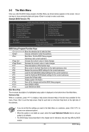
...Chip Configuration ESC: Quit F8: Q-Flash Select Item F10: Save & Exit Setup Change CPU's Clock & Voltage F11: Save CMOS to BIOS F12: Load CMOS from BIOS BIOS Setup Program Function Keys Move the selection bar to select an item Execute command or enter the submenu Main Menu: Exit the...are for the current submenus Access the Q-Flash utility Display system information Save all the changes and exit the BIOS Setup program Save CMOS to BIOS Load CMOS from BIOS Main Menu Help The on-screen description of a highlighted setup option is not stable as shown below) ...
...Chip Configuration ESC: Quit F8: Q-Flash Select Item F10: Save & Exit Setup Change CPU's Clock & Voltage F11: Save CMOS to BIOS F12: Load CMOS from BIOS BIOS Setup Program Function Keys Move the selection bar to select an item Execute command or enter the submenu Main Menu: Exit the...are for the current submenus Access the Q-Flash utility Display system information Save all the changes and exit the BIOS Setup program Save CMOS to BIOS Load CMOS from BIOS Main Menu Help The on-screen description of a highlighted setup option is not stable as shown below) ...

Manual
Page 36
... created before, without the hassles of the and keys (For the Main Menu Only) F11: Save CMOS to BIOS This function allows you to save the current BIOS settings to see information about autodetected system/CPU temperature, system voltage and fan speed, etc. Load Fail-Safe Defaults...time and date, hard drive types, floppy disk drive types, and the type of errors that stop the system boot, etc. Advanced BIOS Features Use this menu to configure the device boot order, advanced features available on the CPU, and the primary display adapter. Integrated ...
... created before, without the hassles of the and keys (For the Main Menu Only) F11: Save CMOS to BIOS This function allows you to save the current BIOS settings to see information about autodetected system/CPU temperature, system voltage and fan speed, etc. Load Fail-Safe Defaults...time and date, hard drive types, floppy disk drive types, and the type of errors that stop the system boot, etc. Advanced BIOS Features Use this menu to configure the device boot order, advanced features available on the CPU, and the primary display adapter. Integrated ...
Manual
Page 37
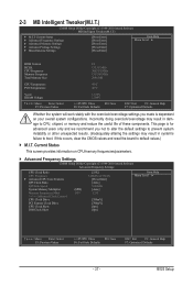
...} Advanced Voltage Settings } Miscellaneous Settings [Press Enter] [Press Enter] [Press Enter] [Press Enter] [Press Enter] Item Help Menu Level BIOS Version BCLK CPU Frequency Memory Frequency Total Memory Size F4 133.38 MHz 3067.81 MHz 1333.88 MHz 2048 MB CPU Temperature PCH Temperature... Help F7: Optimized Defaults - 37 - 2-3 MB Intelligent Tweaker(M.I.T.) CMOS Setup Utility-Copyright (C) 1984-2010 Award Software MB Intelligent Tweaker(M.I.T.) } M.I .T. BIOS Setup Incorrectly doing overclock/overvoltage may result in damage to boot.
...} Advanced Voltage Settings } Miscellaneous Settings [Press Enter] [Press Enter] [Press Enter] [Press Enter] [Press Enter] Item Help Menu Level BIOS Version BCLK CPU Frequency Memory Frequency Total Memory Size F4 133.38 MHz 3067.81 MHz 1333.88 MHz 2048 MB CPU Temperature PCH Temperature... Help F7: Optimized Defaults - 37 - 2-3 MB Intelligent Tweaker(M.I.T.) CMOS Setup Utility-Copyright (C) 1984-2010 Award Software MB Intelligent Tweaker(M.I.T.) } M.I .T. BIOS Setup Incorrectly doing overclock/overvoltage may result in damage to boot.
Manual
Page 38
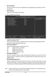
...Note) Allows you to determine whether to decrease power consumption. This feature only works for the installed CPU. All Enables all CPU cores. BIOS Setup - 38 - When enabled, the CPU core frequency and voltage will be reduced during system halt state to enable the Intel CPU ...Turbo Boost technology. Auto lets the BIOS automatically configure this feature. The adjustable range is present only if you install a CPU that support multi-processor mode. (Default: Enabled) CPU...
...Note) Allows you to determine whether to decrease power consumption. This feature only works for the installed CPU. All Enables all CPU cores. BIOS Setup - 38 - When enabled, the CPU core frequency and voltage will be reduced during system halt state to enable the Intel CPU ...Turbo Boost technology. Auto lets the BIOS automatically configure this feature. The adjustable range is present only if you install a CPU that support multi-processor mode. (Default: Enabled) CPU...
Manual
Page 39
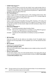
... Monitor function, a CPU overheating protection function. ting. (Default: Auto) Bi-Directional PROCHOT (Note) Auto Enabled Disabled Lets the BIOS automatically configure this set- Only allows the CPU to detect whether an overheating is dependent on CPU loading, Intel EIST technology can... current operating QPI link speed. The adjustable range is occurring to decrease average power consumption and heat production. Auto lets the BIOS automatically configure this setting. (Default: Auto) CPU EIST Function (Note) Enables or disables Enhanced Intel SpeedStep Technology (EIST). ...
... Monitor function, a CPU overheating protection function. ting. (Default: Auto) Bi-Directional PROCHOT (Note) Auto Enabled Disabled Lets the BIOS automatically configure this set- Only allows the CPU to detect whether an overheating is dependent on CPU loading, Intel EIST technology can... current operating QPI link speed. The adjustable range is occurring to decrease average power consumption and heat production. Auto lets the BIOS automatically configure this setting. (Default: Auto) CPU EIST Function (Note) Enables or disables Enhanced Intel SpeedStep Technology (EIST). ...


