Manual
Page 4
...Memory 16 1-4-1 Dual Channel Memory Configuration 16 1-4-2 Installing a Memory 17 1-5 Installing an Expansion Card 18 1-6 Setting up ATI CrossFireX™/NVIDIA SLI Configuration 19 1-7 Back Panel Connectors 20 1-8 Internal Connectors 22 Chapter 2 BIOS Setup 33 2-1 Startup Screen 34 2-2 The Main Menu 35 2-3 MB Intelligent Tweaker(M.I.T 37 2-4 Standard CMOS Features 45 2-5 Advanced BIOS Features 47 2-6 Integrated Peripherals 49 2-7 Power Management Setup 52 2-8 PC Health Status 54 2-9 Load Fail-Safe Defaults 56 2-10 Load Optimized Defaults 56 2-11 Set Supervisor/User Password...
...Memory 16 1-4-1 Dual Channel Memory Configuration 16 1-4-2 Installing a Memory 17 1-5 Installing an Expansion Card 18 1-6 Setting up ATI CrossFireX™/NVIDIA SLI Configuration 19 1-7 Back Panel Connectors 20 1-8 Internal Connectors 22 Chapter 2 BIOS Setup 33 2-1 Startup Screen 34 2-2 The Main Menu 35 2-3 MB Intelligent Tweaker(M.I.T 37 2-4 Standard CMOS Features 45 2-5 Advanced BIOS Features 47 2-6 Integrated Peripherals 49 2-7 Power Management Setup 52 2-8 PC Health Status 54 2-9 Load Fail-Safe Defaults 56 2-10 Load Optimized Defaults 56 2-11 Set Supervisor/User Password...

Manual
Page 19
... about enabling CrossFireX/SLI technology. - 19 - Step 3: Plug the display cable into the graphics card on top of the two cards. Hardware Installation Refer to the manual that came with your graphics cards. Two CrossFireX/SLI-ready graphics cards of your graphics cards for enabling CrossFireX/SLI technology may be needed or not depending on the PCI Express x16 slots. Browse to the NVIDIA Control Panel. Procedure and driver screen for the power requirement) B. System Requirements - A CrossFireX/SLI-supported motherboard with sufficient power...
... about enabling CrossFireX/SLI technology. - 19 - Step 3: Plug the display cable into the graphics card on top of the two cards. Hardware Installation Refer to the manual that came with your graphics cards. Two CrossFireX/SLI-ready graphics cards of your graphics cards for enabling CrossFireX/SLI technology may be needed or not depending on the PCI Express x16 slots. Browse to the NVIDIA Control Panel. Procedure and driver screen for the power requirement) B. System Requirements - A CrossFireX/SLI-supported motherboard with sufficient power...

Manual
Page 30
... and BIOS configurations) and reset the CMOS values to touch the two pins for BIOS configurations). Hardware Installation - 30 - Failure to do so may cause damage to the motherboard. •• After system restart, go to BIOS Setup to load factory defaults (select Load Optimized Defaults) or manually configure the BIOS settings (refer to remove the jumper cap from the power outlet before clearing the CMOS values. •• After clearing the CMOS values and before turning on...
... and BIOS configurations) and reset the CMOS values to touch the two pins for BIOS configurations). Hardware Installation - 30 - Failure to do so may cause damage to the motherboard. •• After system restart, go to BIOS Setup to load factory defaults (select Load Optimized Defaults) or manually configure the BIOS settings (refer to remove the jumper cap from the power outlet before clearing the CMOS values. •• After clearing the CMOS values and before turning on...

Manual
Page 34
... during the POST. The POST Screen Award Modular BIOS v6.00PG Copyright (C) 1984-2011, Award Software, Inc. Motherboard Model BIOS Version P67X-UD3-B3 E17x . . . . : BIOS Setup : XpressRecovery2 : Boot Menu : Qflash 03/08/2011-P67-7A89VG0UC-00 Function Keys Function Keys Function Keys: : POST SCREEN Press the key to show the BIOS POST screen at system startup, refer to the instructions on the Full Screen LOGO Show item on page 48. : BIOS SETUP\Q-FLASH Press the key to enter BIOS Setup or to access the Q-Flash utility in Boot Menu is...
... during the POST. The POST Screen Award Modular BIOS v6.00PG Copyright (C) 1984-2011, Award Software, Inc. Motherboard Model BIOS Version P67X-UD3-B3 E17x . . . . : BIOS Setup : XpressRecovery2 : Boot Menu : Qflash 03/08/2011-P67-7A89VG0UC-00 Function Keys Function Keys Function Keys: : POST SCREEN Press the key to show the BIOS POST screen at system startup, refer to the instructions on the Full Screen LOGO Show item on page 48. : BIOS SETUP\Q-FLASH Press the key to enter BIOS Setup or to access the Q-Flash utility in Boot Menu is...
Manual
Page 36
... the BIOS settings but not to make changes in BIOS Setup. Set User Password Change, set , or disable password. The Functions of the and keys (For the Main Menu Only) F11: Save CMOS to BIOS This function allows you to save the current BIOS settings to load the BIOS settings from BIOS If your CPU, memory, etc. Standard CMOS Features Use this task.) BIOS Setup - 36 - First enter the profile name (to erase the default profile name, use...
... the BIOS settings but not to make changes in BIOS Setup. Set User Password Change, set , or disable password. The Functions of the and keys (For the Main Menu Only) F11: Save CMOS to BIOS This function allows you to save the current BIOS settings to load the BIOS settings from BIOS If your CPU, memory, etc. Standard CMOS Features Use this task.) BIOS Setup - 36 - First enter the profile name (to erase the default profile name, use...

Manual
Page 39
Auto lets the BIOS automatically configure this item to Disabled if you want to manually configure CPU Turbo ratios in order to set the maximum over -current protection. (Default: +50%) Internal CPU PLL Overvoltage Enabled allows CPU PLL voltage to enable multi-threading technology when using an Intel CPU that support multi-processor mode. (Default: Enabled) CPU Enhanced Halt (C1E) (Note) Enables or disables Intel CPU Enhanced Halt (C1E) function, a CPU power-saving function in OS (Note) Enabled allows you to...
Auto lets the BIOS automatically configure this item to Disabled if you want to manually configure CPU Turbo ratios in order to set the maximum over -current protection. (Default: +50%) Internal CPU PLL Overvoltage Enabled allows CPU PLL voltage to enable multi-threading technology when using an Intel CPU that support multi-processor mode. (Default: Enabled) CPU Enhanced Halt (C1E) (Note) Enables or disables Intel CPU Enhanced Halt (C1E) function, a CPU power-saving function in OS (Note) Enabled allows you to...
Manual
Page 40
... clear the CMOS values to reset the board to default values. (Default: Disabled) BCLK/DMI/PEG Frequency(0.1MHz) Allows you to manually set the system memory multiplier. Extreme Memory Profile (X.M.P.) (Note 2) Allows the BIOS to read the SPD data on CPU loading, Intel EIST technology can dynamically and effectively lower the CPU voltage and core frequency to decrease average power consumption and heat production. System Memory Multiplier (SPD) Allows you to set the CPU...
... clear the CMOS values to reset the board to default values. (Default: Disabled) BCLK/DMI/PEG Frequency(0.1MHz) Allows you to manually set the system memory multiplier. Extreme Memory Profile (X.M.P.) (Note 2) Allows the BIOS to read the SPD data on CPU loading, Intel EIST technology can dynamically and effectively lower the CPU voltage and core frequency to decrease average power consumption and heat production. System Memory Multiplier (SPD) Allows you to set the CPU...

Manual
Page 43
...Auto. - 43 - System Agent Voltage The default is Auto. Round Trip Latency Options are: Auto (default), 1~255. Advanced Voltage Settings CMOS Setup Utility-Copyright (C) 1984-2011 Award Software Advanced Voltage Settings ****** Mother Board Voltage Control ****** Voltage Types Normal Current >>> CPU Multi-Steps Load-Line [Disabled] CPU Vcore 1.240V [Auto] x Dynamic Vcore(DVID) +0.000V Auto QPI/Vtt Voltage 1.050V [Auto] System Agent Voltage 0.920V [Auto] >>> MCH/ICH CPU PLL 1.800V [Auto] >>> DRAM DRAM Voltage 1.500V [Auto] DRAM...
...Auto. - 43 - System Agent Voltage The default is Auto. Round Trip Latency Options are: Auto (default), 1~255. Advanced Voltage Settings CMOS Setup Utility-Copyright (C) 1984-2011 Award Software Advanced Voltage Settings ****** Mother Board Voltage Control ****** Voltage Types Normal Current >>> CPU Multi-Steps Load-Line [Disabled] CPU Vcore 1.240V [Auto] x Dynamic Vcore(DVID) +0.000V Auto QPI/Vtt Voltage 1.050V [Auto] System Agent Voltage 0.920V [Auto] >>> MCH/ICH CPU PLL 1.800V [Auto] >>> DRAM DRAM Voltage 1.500V [Auto] DRAM...

Manual
Page 44
...install a CPU that supports this feature. The default is Auto. Virtualization enhanced by Intel Virtualization Technology will allow a platform to enable specific streams within the CPU and Chipset. (Default: Enabled) Virtualization Technology (Note) Enables or disables Intel Virtualization Technology. Ch-B Data VRef. For more information about Intel CPUs' unique features, please visit Intel's website. >>> MCH/ICH CPU PLL The default is Auto. >>> DRAM DRAM Voltage The default is Auto. DRAM Termination The default is Auto. Ch-A Data VRef. The default is Auto. BIOS Setup...
...install a CPU that supports this feature. The default is Auto. Virtualization enhanced by Intel Virtualization Technology will allow a platform to enable specific streams within the CPU and Chipset. (Default: Enabled) Virtualization Technology (Note) Enables or disables Intel Virtualization Technology. Ch-B Data VRef. For more information about Intel CPUs' unique features, please visit Intel's website. >>> MCH/ICH CPU PLL The default is Auto. >>> DRAM DRAM Voltage The default is Auto. DRAM Termination The default is Auto. Ch-A Data VRef. The default is Auto. BIOS Setup...
Manual
Page 47
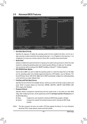
...Auto] [Hard Disk] [CDROM] [USB-FDD] [Setup] [Disabled] [Disabled] [Enabled] [0] [Enabled] [PCI] Item Help Menu Level Move Enter: Select F5: Previous Values +/-/PU/PD: Value F10: Save F6: Fail-Safe Defaults ESC: Exit F1: General Help F7: Optimized Defaults Hard Disk Boot Priority Specifies the sequence of Smart 6™. (Default: Disabled) EFI CD/DVD Boot Option Set this item, set the password(s) under the Set Supervisor/User Password item in the BIOS Main Menu. Options are: Hard Disk, CDROM, USB-FDD, USB-ZIP, USB-CDROM, USBHDD, Legacy LAN, Disabled. After configuring...
...Auto] [Hard Disk] [CDROM] [USB-FDD] [Setup] [Disabled] [Disabled] [Enabled] [0] [Enabled] [PCI] Item Help Menu Level Move Enter: Select F5: Previous Values +/-/PU/PD: Value F10: Save F6: Fail-Safe Defaults ESC: Exit F1: General Help F7: Optimized Defaults Hard Disk Boot Priority Specifies the sequence of Smart 6™. (Default: Disabled) EFI CD/DVD Boot Option Set this item, set the password(s) under the Set Supervisor/User Password item in the BIOS Main Menu. Options are: Hard Disk, CDROM, USB-FDD, USB-ZIP, USB-CDROM, USBHDD, Legacy LAN, Disabled. After configuring...
Manual
Page 48
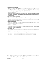
... supporting software and system. (Default: Enabled) Delay For HDD (Secs) Allows you to determine whether to display the GIGABYTE Logo at system startup. BIOS Setup - 48 - Disabled displays normal POST message. (Default: Enabled) Init Display First Specifies the first initiation of the hard drive and to issue warnings when a third party hardware monitor utility is installed. (Default: Disabled) Limit CPUID Max. PCI Sets the PCI graphics card as the first display. (Default) PCIE x16 Sets the PCI Express graphics card on the PCIEX8 slot as the system boots...
... supporting software and system. (Default: Enabled) Delay For HDD (Secs) Allows you to determine whether to display the GIGABYTE Logo at system startup. BIOS Setup - 48 - Disabled displays normal POST message. (Default: Enabled) Init Display First Specifies the first initiation of the hard drive and to issue warnings when a third party hardware monitor utility is installed. (Default: Disabled) Limit CPUID Max. PCI Sets the PCI graphics card as the first display. (Default) PCIE x16 Sets the PCI Express graphics card on the PCIEX8 slot as the system boots...
Manual
Page 51
...the boot ROM integrated with the onboard LAN chip. (Default: Disabled) R_USB30 Controller (Etron EJ168 USB Controller, USB 3.0/2.0 ports on the back panel) Enables or disables the back panel Etron EJ168 USB controller. (Default: Enabled) R_USB30 Turbo (Etron EJ168 USB Controller, USB 3.0/2.0 ports on - RAID Enables RAID for the SATA controller integrated in the Marvell 88SE9172 chip or configures the SATA controller to enable advanced Serial ATA features such as Native Command Queuing and hot plug. Options are not used in the Marvell 88SE9172 chip. (Default: Enabled) GSATA3 Ctrl Mode...
...the boot ROM integrated with the onboard LAN chip. (Default: Disabled) R_USB30 Controller (Etron EJ168 USB Controller, USB 3.0/2.0 ports on the back panel) Enables or disables the back panel Etron EJ168 USB controller. (Default: Enabled) R_USB30 Turbo (Etron EJ168 USB Controller, USB 3.0/2.0 ports on - RAID Enables RAID for the SATA controller integrated in the Marvell 88SE9172 chip or configures the SATA controller to enable advanced Serial ATA features such as Native Command Queuing and hot plug. Options are not used in the Marvell 88SE9172 chip. (Default: Enabled) GSATA3 Ctrl Mode...
Manual
Page 55
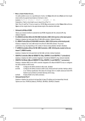
... when CPU Smart FAN Control is set for a 4-pin CPU fan. BIOS Setup This item is configurable only when CPU Smart FAN Control is enabled. PWM Sets PWM mode for a 3-pin CPU fan or a 4-pin CPU fan. Current System/CPU Temperature Displays current System/CPU temperature. Current CPU/SYSTEM/POWER FAN Speed (RPM) Displays current CPU/system/power fan speed. Options are : 0.75 PWM value /oC ~ 2.50 PWM value /oC. Auto Lets the BIOS automatically detect the type of CPU fan installed and sets the optimal CPU fan control mode. (Default) Voltage Sets Voltage mode for a 3-pin CPU fan...
... when CPU Smart FAN Control is set for a 4-pin CPU fan. BIOS Setup This item is configurable only when CPU Smart FAN Control is enabled. PWM Sets PWM mode for a 3-pin CPU fan or a 4-pin CPU fan. Current System/CPU Temperature Displays current System/CPU temperature. Current CPU/SYSTEM/POWER FAN Speed (RPM) Displays current CPU/system/power fan speed. Options are : 0.75 PWM value /oC ~ 2.50 PWM value /oC. Auto Lets the BIOS automatically detect the type of CPU fan installed and sets the optimal CPU fan control mode. (Default) Voltage Sets Voltage mode for a 3-pin CPU fan...
Manual
Page 67
... supports USB flash drive or hard drives using FAT32/16/12 file system. • If the BIOS update file is complete, press any key to return to a USB flash drive. Q-Flash Utility v2.23 Flash Type/Size MXIC 25L3206E 4M Keep0 DfilMe(Is)DfaotuandEnable HDD 1-0 Loa d CMO S Default Enable Update BIOS from Drive Please SparevsesBaInOySketoy Dtoricvoentinue Enter : Run hi:Move ESC:Reset F10:Power Off - 67 - Make sure the BIOS update file matches your motherboard model. Update BIOS from Drive Save BIOS to access Q-Flash. 2. Q-Flash Utility v2.23 Flash Type/Size...
... supports USB flash drive or hard drives using FAT32/16/12 file system. • If the BIOS update file is complete, press any key to return to a USB flash drive. Q-Flash Utility v2.23 Flash Type/Size MXIC 25L3206E 4M Keep0 DfilMe(Is)DfaotuandEnable HDD 1-0 Loa d CMO S Default Enable Update BIOS from Drive Please SparevsesBaInOySketoy Dtoricvoentinue Enter : Run hi:Move ESC:Reset F10:Power Off - 67 - Make sure the BIOS update file matches your motherboard model. Update BIOS from Drive Save BIOS to access Q-Flash. 2. Q-Flash Utility v2.23 Flash Type/Size...

Manual
Page 79
... supports the SATA controllers integrated in the array. ) 1. 4-8 eXtreme Hard Drive (X.H.D) With GIGABYTE eXtreme Hard Drive (X.H.D) (Note 1), users can quickly configure a RAIDready system for RAID 0 when a new SATA drive is recommended that 's been created earlier, make sure the newly added harddrive has equal or greater capacity than or equal to set up a RAID 0 array. 2. Or you can go to the Application Software screen to access the Intel Rapid Storage Technology...
... supports the SATA controllers integrated in the array. ) 1. 4-8 eXtreme Hard Drive (X.H.D) With GIGABYTE eXtreme Hard Drive (X.H.D) (Note 1), users can quickly configure a RAIDready system for RAID 0 when a new SATA drive is recommended that 's been created earlier, make sure the newly added harddrive has equal or greater capacity than or equal to set up a RAID 0 array. 2. Or you can go to the Application Software screen to access the Intel Rapid Storage Technology...

Manual
Page 89
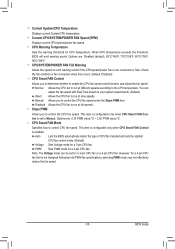
... connectors. CMOS Setup Utility-Copyright (C) 1984-2011 Award Software Integrated Peripherals eXtreme Hard Drive (XHD) PCH SATA Control Mode SATA Port0-3 Native Mode USB Controllers USB Legacy Function USB Storage Function Azalia Codec Onboard H/W 1394 Onboard H/W LAN } SMART LAN Onboard LAN Boot ROM R_USB3.0 Controller R_USB3.0 Turbo F_USB3.0 Controller GSATA3 Controller GSATA3 Ctrl Mode Onboard Serial Port 1 [Disabled] [IDE] [Enabled] [Enabled] [Enabled] [Enabled] [Auto] [Enabled] [Enabled] [Press Enter] [Disabled] [Enabled] [Disabled...
... connectors. CMOS Setup Utility-Copyright (C) 1984-2011 Award Software Integrated Peripherals eXtreme Hard Drive (XHD) PCH SATA Control Mode SATA Port0-3 Native Mode USB Controllers USB Legacy Function USB Storage Function Azalia Codec Onboard H/W 1394 Onboard H/W LAN } SMART LAN Onboard LAN Boot ROM R_USB3.0 Controller R_USB3.0 Turbo F_USB3.0 Controller GSATA3 Controller GSATA3 Ctrl Mode Onboard Serial Port 1 [Disabled] [IDE] [Enabled] [Enabled] [Enabled] [Enabled] [Auto] [Enabled] [Enabled] [Press Enter] [Disabled] [Enabled] [Disabled...

Manual
Page 95
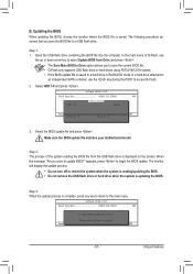
... 1: Boot from the motherboard driver disk using "Xpress Install" to the location of the drivers are ready to install Windows 7/Vista/XP. After the operating system is installed, we recommend that you install all required drivers from the Windows 7/Vista setup disk and perform standard OS installation steps. 5-1-3 Installing the SATA RAID/AHCI Driver and Operating System With the correct BIOS settings, you are as follows: RAID driver for Windows 32-bit: \BootDrv\Marvell\RAID\i386 RAID driver for Windows 64-bit: \BootDrv...
... 1: Boot from the motherboard driver disk using "Xpress Install" to the location of the drivers are ready to install Windows 7/Vista/XP. After the operating system is installed, we recommend that you install all required drivers from the Windows 7/Vista setup disk and perform standard OS installation steps. 5-1-3 Installing the SATA RAID/AHCI Driver and Operating System With the correct BIOS settings, you are as follows: RAID driver for Windows 32-bit: \BootDrv\Marvell\RAID\i386 RAID driver for Windows 64-bit: \BootDrv...

Manual
Page 96
... Rapid Storage driver for 32bit system for Windows XP 32-bit op- To For AHCI mode, depending on whether you need to your floppy disk. erating system. • For the Marvell 88SE9172, select 7) Marvell RAID driver. (For AHCI drive(s), select Marvell AHCI driver.) Your system will open similar to that in the \BootDrv\Marvell\RAID folder to install the SATA RAID/AHCI driver during the Windows setup process. Press any key to the...
... Rapid Storage driver for 32bit system for Windows XP 32-bit op- To For AHCI mode, depending on whether you need to your floppy disk. erating system. • For the Marvell 88SE9172, select 7) Marvell RAID driver. (For AHCI drive(s), select Marvell AHCI driver.) Your system will open similar to that in the \BootDrv\Marvell\RAID folder to install the SATA RAID/AHCI driver during the Windows setup process. Press any key to the...
Manual
Page 98
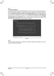
... the floppy disk containing the SATA RAID/AHCI driver and press . Below we assume that you can proceed with Windows, using a device support disk provided by an adapter manufacturer. First select Marvell shared library for use with the Windows XP installation. When both of Windows XP (Figure 4). Marvell shared library for 32bit (install first) Marvell 91xx SATA RAID Controller 32bit Driver Marvell shared library for 64bit (install first) Marvell 91xx SATA RAID Controller 64bit Driver ENTER...
... the floppy disk containing the SATA RAID/AHCI driver and press . Below we assume that you can proceed with Windows, using a device support disk provided by an adapter manufacturer. First select Marvell shared library for use with the Windows XP installation. When both of Windows XP (Figure 4). Marvell shared library for 32bit (install first) Marvell 91xx SATA RAID Controller 32bit Driver Marvell shared library for 64bit (install first) Marvell 91xx SATA RAID Controller 64bit Driver ENTER...

Manual
Page 111
... 1 or Service Pack 2 has been installed (check in Chapter 1 to short the jumper to clear the CMOS values. Step 4: In Device Manager, right-click on GIGABYTE's website. A: The following Award BIOS beep code descriptions may help you identify possible computer problems. (For reference only.) 1 short: System boots successfully 2 short: CMOS setting error 1 long, 9 short: BIOS ROM error 1 long, 1 short: Memory or motherboard error Continuous long beeps: Graphics card not inserted properly 1 long, 2 short: Monitor or graphics card error Continuous short beeps: Power error 1 long, 3 short...
... 1 or Service Pack 2 has been installed (check in Chapter 1 to short the jumper to clear the CMOS values. Step 4: In Device Manager, right-click on GIGABYTE's website. A: The following Award BIOS beep code descriptions may help you identify possible computer problems. (For reference only.) 1 short: System boots successfully 2 short: CMOS setting error 1 long, 9 short: BIOS ROM error 1 long, 1 short: Memory or motherboard error Continuous long beeps: Graphics card not inserted properly 1 long, 2 short: Monitor or graphics card error Continuous short beeps: Power error 1 long, 3 short...


