Manual
Page 1
GA-P67A-UD3R-B3 LGA1155 socket motherboard for Intel® Core™ i7 processors/ Intel® Core™ i5 processors/Intel® Core™ i3 processors/ Intel® Pentium® processors/Intel® Celeron® processors User's Manual Rev. 1101 12ME-P67A3RB-1101R
GA-P67A-UD3R-B3 LGA1155 socket motherboard for Intel® Core™ i7 processors/ Intel® Core™ i5 processors/Intel® Core™ i3 processors/ Intel® Pentium® processors/Intel® Celeron® processors User's Manual Rev. 1101 12ME-P67A3RB-1101R
Manual
Page 2
Motherboard GA-P67A-UD3R-B3 Oct. 26, 2010 Motherboard GA-P67A-UD3R-B3 Oct. 26, 2010
Motherboard GA-P67A-UD3R-B3 Oct. 26, 2010 Motherboard GA-P67A-UD3R-B3 Oct. 26, 2010
Manual
Page 3
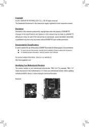
... this : "REV: X.X." For product-related information, check on our website at: http://www.gigabyte.com Identifying Your Motherboard Revision The revision number on your motherboard revision before updating motherboard BIOS, drivers, or when looking for technical information. For example, "REV: 1.0" means the ...manual is the property of this product, GIGABYTE provides the following types of documentations: For quick set-up of the motherboard is 1.0. Changes to their respective owners. Example: Check your motherboard looks like this manual are legally registered ...
... this : "REV: X.X." For product-related information, check on our website at: http://www.gigabyte.com Identifying Your Motherboard Revision The revision number on your motherboard revision before updating motherboard BIOS, drivers, or when looking for technical information. For example, "REV: 1.0" means the ...manual is the property of this product, GIGABYTE provides the following types of documentations: For quick set-up of the motherboard is 1.0. Changes to their respective owners. Example: Check your motherboard looks like this manual are legally registered ...
Manual
Page 4
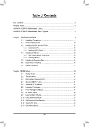
Table of Contents Box Contents...6 Optional Items...6 GA-P67A-UD3R-B3 Motherboard Layout 7 GA-P67A-UD3R-B3 Motherboard Block Diagram 8 Chapter 1 Hardware Installation 9 1-1 Installation Precautions 9 1-2 Product Specifications 10 1-3 Installing the CPU and CPU Cooler 13 1-3-1 Installing the CPU 13 1-3-2 Installing the CPU Cooler ...
Table of Contents Box Contents...6 Optional Items...6 GA-P67A-UD3R-B3 Motherboard Layout 7 GA-P67A-UD3R-B3 Motherboard Block Diagram 8 Chapter 1 Hardware Installation 9 1-1 Installation Precautions 9 1-2 Product Specifications 10 1-3 Installing the CPU and CPU Cooler 13 1-3-1 Installing the CPU 13 1-3-2 Installing the CPU Cooler ...
Manual
Page 6
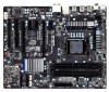
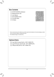
Optional Items 2-port USB 2.0 bracket (Part No. 12CR1-1UB030-5*R) 2-port SATA power cable (Part No. 12CF1-2SERPW-0*R) COM port cable (Part No. 12CF1-1CM001-3*R) - 6 - The box contents are for reference only. Box Contents GA-P67A-UD3R-B3 motherboard Motherboard driver disk User's Manual Quick Installation Guide Four SATA cables I/O Shield • The box contents above are subject to change without notice. • The motherboard image is for reference only and the actual items shall depend on the product package you obtain.
Optional Items 2-port USB 2.0 bracket (Part No. 12CR1-1UB030-5*R) 2-port SATA power cable (Part No. 12CF1-2SERPW-0*R) COM port cable (Part No. 12CF1-1CM001-3*R) - 6 - The box contents are for reference only. Box Contents GA-P67A-UD3R-B3 motherboard Motherboard driver disk User's Manual Quick Installation Guide Four SATA cables I/O Shield • The box contents above are subject to change without notice. • The motherboard image is for reference only and the actual items shall depend on the product package you obtain.
Manual
Page 7
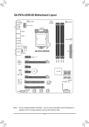
GA-P67A-UD3R-B3 Motherboard Layout KB_MS_USB R_SPDIF SYS_FAN1 ATX_12V_2X4 R_USB_2 R_USB_1 R_USB30 LGA1155 CPU_FAN PHASE LED PWR_FAN USB_LAN Renesas D720200 AUDIO F_AUDIO GA-P67A-UD3R-B3 Realtek RTL8111E PCIEX1_1 (Note) PCIEX16 PCIEX1_2 CODEC PCIEX1_3 BAT SPDIF_O PCIEX4 iTE IT8728 COMA PCI1 PCI2 SYS_FAN2 F_USB3 F_USB2 iTE IT8892 Bridge F_USB1 DDR3_1 DDR3_2 ...
GA-P67A-UD3R-B3 Motherboard Layout KB_MS_USB R_SPDIF SYS_FAN1 ATX_12V_2X4 R_USB_2 R_USB_1 R_USB30 LGA1155 CPU_FAN PHASE LED PWR_FAN USB_LAN Renesas D720200 AUDIO F_AUDIO GA-P67A-UD3R-B3 Realtek RTL8111E PCIEX1_1 (Note) PCIEX16 PCIEX1_2 CODEC PCIEX1_3 BAT SPDIF_O PCIEX4 iTE IT8728 COMA PCI1 PCI2 SYS_FAN2 F_USB3 F_USB2 iTE IT8892 Bridge F_USB1 DDR3_1 DDR3_2 ...
Manual
Page 8
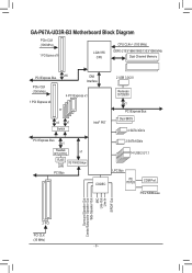
GA-P67A-UD3R-B3 Motherboard Block Diagram PCIe CLK (100 MHz) 1 PCI Express x16 LGA1155 CPU CPU CLK+/- (100 MHz) DDR3 2133/1866/1600/1333/1066 MHz Dual Channel Memory ...
GA-P67A-UD3R-B3 Motherboard Block Diagram PCIe CLK (100 MHz) 1 PCI Express x16 LGA1155 CPU CPU CLK+/- (100 MHz) DDR3 2133/1866/1600/1333/1066 MHz Dual Channel Memory ...
Manual
Page 9
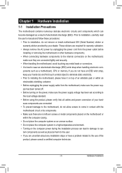
...using the product, please verify that all cables and power connectors of your hardware components are connected. • To prevent damage to the motherboard, do not allow screws to come in a high-temperature environment. • Turning on the power, make sure they are uncertain about any... or connectors. • It is best to wear an electrostatic discharge (ESD) wrist strap when handling electronic com- ponents such as a motherboard, CPU or memory. Hardware Installation These stickers are required for warranty validation. • Always remove the AC power by your dealer. Prior ...
...using the product, please verify that all cables and power connectors of your hardware components are connected. • To prevent damage to the motherboard, do not allow screws to come in a high-temperature environment. • Turning on the power, make sure they are uncertain about any... or connectors. • It is best to wear an electrostatic discharge (ESD) wrist strap when handling electronic com- ponents such as a motherboard, CPU or memory. Hardware Installation These stickers are required for warranty validation. • Always remove the AC power by your dealer. Prior ...
Manual
Page 12
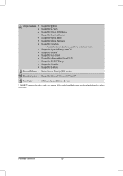
... Charge Support for Cloud OC Support for Q-Share Norton Internet Security (OEM version) Operating System w Support for EasyTune * Available functions in EasyTune may differ by motherboard model. Unique Features w w w w w w w w w w w w w w Bundled Software w Support for @BIOS Support for Q-Flash Support ...Windows® 7/Vista/XP Form Factor w ATX Form Factor; 30.5cm x 24.4cm * GIGABYTE reserves the right to make any changes to the product specifications and product-related information without prior notice.
... Charge Support for Cloud OC Support for Q-Share Norton Internet Security (OEM version) Operating System w Support for EasyTune * Available functions in EasyTune may differ by motherboard model. Unique Features w w w w w w w w w w w w w w Bundled Software w Support for @BIOS Support for Q-Flash Support ...Windows® 7/Vista/XP Form Factor w ATX Form Factor; 30.5cm x 24.4cm * GIGABYTE reserves the right to make any changes to the product specifications and product-related information without prior notice.
Manual
Page 13
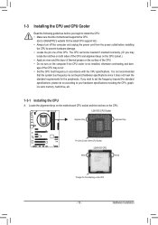
... not meet the standard requirements for the peripherals. Locate the alignment keys on the motherboard CPU socket and the notches on the computer if the CPU cooler is not recommended that the motherboard supports the CPU. (Go to GIGABYTE's website for the latest CPU support list.) • Always turn on the CPU. Hardware...
... not meet the standard requirements for the peripherals. Locate the alignment keys on the motherboard CPU socket and the notches on the computer if the CPU cooler is not recommended that the motherboard supports the CPU. (Go to GIGABYTE's website for the latest CPU support list.) • Always turn on the CPU. Hardware...

Manual
Page 14
... power outlet to prevent damage to lightly replace the load plate. When replacing the load plate, make sure to correctly install the CPU into the motherboard CPU socket. B. Step 1: Gently press the CPU socket lever handle down on the rear grip of the socket cover and use one corner of the...
... power outlet to prevent damage to lightly replace the load plate. When replacing the load plate, make sure to correctly install the CPU into the motherboard CPU socket. B. Step 1: Gently press the CPU socket lever handle down on the rear grip of the socket cover and use one corner of the...
Manual
Page 15
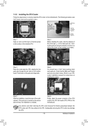
...The Top of Female Push Pin Female Push Pin Step 1: Apply an even and thin layer of thermal grease on the surface of the motherboard. Check that the Male and Female push pins are joined closely. (Refer to your CPU cooler installation manual for instructions on installing the cooler...cooler and CPU may damage the CPU. - 15 - 1-3-2 Installing the CPU Cooler Follow the steps below to correctly install the CPU cooler on the motherboard. (The following procedure uses Intel® boxed cooler as the picture above shows, the installation is complete. Push down each push pin. Step 6: Finally...
...The Top of Female Push Pin Female Push Pin Step 1: Apply an even and thin layer of thermal grease on the surface of the motherboard. Check that the Male and Female push pins are joined closely. (Refer to your CPU cooler installation manual for instructions on installing the cooler...cooler and CPU may damage the CPU. - 15 - 1-3-2 Installing the CPU Cooler Follow the steps below to correctly install the CPU cooler on the motherboard. (The following procedure uses Intel® boxed cooler as the picture above shows, the installation is complete. Push down each push pin. Step 6: Finally...
Manual
Page 16
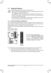
.../SS - Dual Channel mode cannot be used . (Go to insert the memory, switch the direction. 1-4-1 Dual Channel Memory Configuration This motherboard provides four DDR3 memory sockets and supports Dual Channel Technology. It is recommended that memory of the same capacity, brand, speed, and chips...SS - When enabling Dual Channel mode with two or four memory modules, it is recommended that the motherboard supports the memory. The four DDR3 memory sockets are unable to GIGABYTE's website for optimum performance. A memory module can be used for the latest supported memory speeds and ...
.../SS - Dual Channel mode cannot be used . (Go to insert the memory, switch the direction. 1-4-1 Dual Channel Memory Configuration This motherboard provides four DDR3 memory sockets and supports Dual Channel Technology. It is recommended that memory of the same capacity, brand, speed, and chips...SS - When enabling Dual Channel mode with two or four memory modules, it is recommended that the motherboard supports the memory. The four DDR3 memory sockets are unable to GIGABYTE's website for optimum performance. A memory module can be used for the latest supported memory speeds and ...
Manual
Page 17
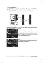
... direction. Place the memory module on the memory and insert it can only fit in the memory sockets. As indicated in the picture on this motherboard. Notch DDR3 DIMM A DDR3 memory module has a notch, so it vertically into place when the memory module is securely inserted. - 17 - Step 2: The clips at...
... direction. Place the memory module on the memory and insert it can only fit in the memory sockets. As indicated in the picture on this motherboard. Notch DDR3 DIMM A DDR3 memory module has a notch, so it vertically into place when the memory module is securely inserted. - 17 - Step 2: The clips at...
Manual
Page 18
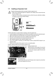
... Express slot. PCI Express x1 Slot PCI Express x16 Slot PCI Slot Follow the steps below to install an expansion card: • Make sure the motherboard supports the expansion card. Align the card with a screw. 5. Secure the card's metal bracket to the chassis back panel with the slot, and press down...
... Express slot. PCI Express x1 Slot PCI Express x16 Slot PCI Slot Follow the steps below to install an expansion card: • Make sure the motherboard supports the expansion card. Align the card with a screw. 5. Secure the card's metal bracket to the chassis back panel with the slot, and press down...
Manual
Page 19
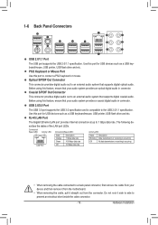
... receiving is occurring Off No data transmission or receiving is compatible to an external audio system that your device and then remove it from the motherboard. • When removing the cable, pull it side to side to connect a PS/2 keyboard or mouse. Hardware Installation Coaxial S/PDIF Out Connector This connector provides...
... receiving is occurring Off No data transmission or receiving is compatible to an external audio system that your device and then remove it from the motherboard. • When removing the cable, pull it side to side to connect a PS/2 keyboard or mouse. Hardware Installation Coaxial S/PDIF Out Connector This connector provides...
Manual
Page 21
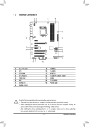
... 9 12 9) F_PANEL 10) F_AUDIO 11) SPDIF_O 12) F_USB1/F_USB2/F_USB3 13) COMA 14) CLR_CMOS 15) PHASE LED Read the following guidelines before turning on the motherboard. - 21 - Unplug the power cord from the power outlet to prevent damage to the devices. • After installing the device and before connecting external devices...
... 9 12 9) F_PANEL 10) F_AUDIO 11) SPDIF_O 12) F_USB1/F_USB2/F_USB3 13) COMA 14) CLR_CMOS 15) PHASE LED Read the following guidelines before turning on the motherboard. - 21 - Unplug the power cord from the power outlet to prevent damage to the devices. • After installing the device and before connecting external devices...
Manual
Page 22
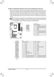
... lead to an unstable or unbootable system. 8 4 5 1 ATX_12V_2X4 ATX_12V_2X4: Pin No. If the 12V power connector is turned off and all the components on the motherboard. 1/2) ATX_12V_2X4/ATX (2x4 12V Power Connector and 2x12 Main Power Connector) With the use of the power connector, the power supply can withstand high power...
... lead to an unstable or unbootable system. 8 4 5 1 ATX_12V_2X4 ATX_12V_2X4: Pin No. If the 12V power connector is turned off and all the components on the motherboard. 1/2) ATX_12V_2X4/ATX (2x4 12V Power Connector and 2x12 Main Power Connector) With the use of the power connector, the power supply can withstand high power...
Manual
Page 23
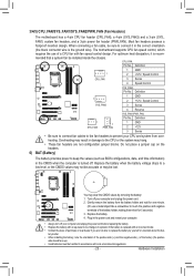
...Plug in the power cord and restart your computer. • Always turn off your computer and unplug the power cord. 2. The motherboard supports CPU fan speed control, which requires the use a metal object like a screwdriver to replace the battery by removing the battery:... date, and time information) in damage to connect it is replaced with local environmental regulations. - 23 - 3/4/5) CPU_FAN/SYS_FAN1/SYS_FAN2/PWR_FAN (Fan Headers) The motherboard has a 4-pin CPU fan header (CPU_FAN), a 4-pin (SYS_FAN2) and a 3-pin (SYS_ FAN1) system fan headers, and a 3-pin power fan ...
...Plug in the power cord and restart your computer. • Always turn off your computer and unplug the power cord. 2. The motherboard supports CPU fan speed control, which requires the use a metal object like a screwdriver to replace the battery by removing the battery:... date, and time information) in damage to connect it is replaced with local environmental regulations. - 23 - 3/4/5) CPU_FAN/SYS_FAN1/SYS_FAN2/PWR_FAN (Fan Headers) The motherboard has a 4-pin CPU fan header (CPU_FAN), a 4-pin (SYS_FAN2) and a 3-pin (SYS_ FAN1) system fan headers, and a 3-pin power fan ...
Manual
Page 26
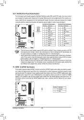
...5, "Configuring 2/4/5.1/7.1-Channel Audio." • Audio signals will make the device unable to the graphics card and have digital audio output from your motherboard to Chapter 5, "Configuring 2/4/5.1/7.1-Channel Audio." • Some chassis provide a front panel audio module that has different wire assignments, please contact ... S/PDIF Out and connects a S/PDIF digital audio cable (provided by default. For example, some graphics cards may connect your motherboard to certain expansion cards like graphics cards and sound cards. If you wish to connect an HDMI display to work or even ...
...5, "Configuring 2/4/5.1/7.1-Channel Audio." • Audio signals will make the device unable to the graphics card and have digital audio output from your motherboard to Chapter 5, "Configuring 2/4/5.1/7.1-Channel Audio." • Some chassis provide a front panel audio module that has different wire assignments, please contact ... S/PDIF Out and connects a S/PDIF digital audio cable (provided by default. For example, some graphics cards may connect your motherboard to certain expansion cards like graphics cards and sound cards. If you wish to connect an HDMI display to work or even ...


