Manual
Page 1
GA-P55A-UD4P GA-P55A-UD4 LGA1156 socket motherboard for Intel® Core™ i7 processor family/ Intel® Core™ i5 processor family User's Manual Rev. 1002 12ME-P55AU4P-1002R
GA-P55A-UD4P GA-P55A-UD4 LGA1156 socket motherboard for Intel® Core™ i7 processor family/ Intel® Core™ i5 processor family User's Manual Rev. 1002 12ME-P55AU4P-1002R
Manual
Page 2
Motherboard GA-P55A-UD4P/GA-P55A-UD4 Oct. 16, 2009 Motherboard GA-P55A-UD4P / GA-P55A-UD4 Oct. 16, 2009
Motherboard GA-P55A-UD4P/GA-P55A-UD4 Oct. 16, 2009 Motherboard GA-P55A-UD4P / GA-P55A-UD4 Oct. 16, 2009
Manual
Page 4
Table of Contents Box Contents...6 Optional Items...6 GA-P55A-UD4P/GA-P55A-UD4 Motherboard Layout 7 Block Diagram...8 Chapter 1 Hardware Installation 9 1-1 Installation Precautions 9 1-2 Product Specifications 10 1-3 Installing the CPU and CPU Cooler 13 1-3-1 Installing the CPU 13 1-3-2 Installing the CPU ...
Table of Contents Box Contents...6 Optional Items...6 GA-P55A-UD4P/GA-P55A-UD4 Motherboard Layout 7 Block Diagram...8 Chapter 1 Hardware Installation 9 1-1 Installation Precautions 9 1-2 Product Specifications 10 1-3 Installing the CPU and CPU Cooler 13 1-3-1 Installing the CPU 13 1-3-2 Installing the CPU ...
Manual
Page 6
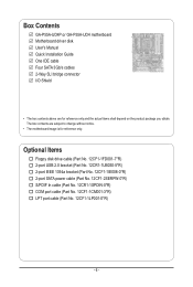
The box contents are for reference only. Box Contents GA-P55A-UD4P or GA-P55A-UD4 motherboard Motherboard driver disk User's Manual Quick Installation Guide One IDE cable Four SATA 3Gb/s cables 2-Way SLI bridge connector I/O Shield • The box contents above are subject to change without notice. • The motherboard image is for reference only and the actual items...
The box contents are for reference only. Box Contents GA-P55A-UD4P or GA-P55A-UD4 motherboard Motherboard driver disk User's Manual Quick Installation Guide One IDE cable Four SATA 3Gb/s cables 2-Way SLI bridge connector I/O Shield • The box contents above are subject to change without notice. • The motherboard image is for reference only and the actual items...
Manual
Page 7
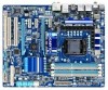
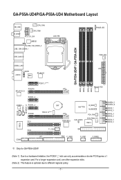
GA-P55A-UD4P/GA-P55A-UD4 Motherboard Layout KB_USB R_SPDIF CPU_FAN SYS_FAN1 ATX_12V_2X4 JMB362 USB_1394_ESATA_2 USB_1394_ESATA_1 USB_LAN2 j LGA1156 PHASE LED PWR_FAN GA-P55A-UD4P / GA-P55A-UD4 DDR3_2 DDR3_1 DDR3_4 DDR3_3 USB30_LAN1 ATX F_AUDIO AUDIO NEC RTL8111D PCIEX1_1(Note 1) PCIEX16...PCH_FAN SYS_FAN2 IT8213 GSATA3_7 GSATA3_6 SATA2_1 SATA2_0 SATA2_3 SATA2_2 SATA2_5 SATA2_4 IT8720 PCI2 COMA F1_1394 LPT IDE FDD F_USB2 F_USB1 F_PANEL j Only for GA-P55A-UD4P. (Note 1) Due to different regional policy. - 7 - For a longer expansion card, use other expansion slots. (Note 2) ...
GA-P55A-UD4P/GA-P55A-UD4 Motherboard Layout KB_USB R_SPDIF CPU_FAN SYS_FAN1 ATX_12V_2X4 JMB362 USB_1394_ESATA_2 USB_1394_ESATA_1 USB_LAN2 j LGA1156 PHASE LED PWR_FAN GA-P55A-UD4P / GA-P55A-UD4 DDR3_2 DDR3_1 DDR3_4 DDR3_3 USB30_LAN1 ATX F_AUDIO AUDIO NEC RTL8111D PCIEX1_1(Note 1) PCIEX16...PCH_FAN SYS_FAN2 IT8213 GSATA3_7 GSATA3_6 SATA2_1 SATA2_0 SATA2_3 SATA2_2 SATA2_5 SATA2_4 IT8720 PCI2 COMA F1_1394 LPT IDE FDD F_USB2 F_USB1 F_PANEL j Only for GA-P55A-UD4P. (Note 1) Due to different regional policy. - 7 - For a longer expansion card, use other expansion slots. (Note 2) ...
Manual
Page 12
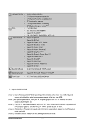
... Internet Security (OEM version) Operating System w Support for Microsoft® Windows® 7/Vista/XP Form Factor w ATX Form Factor; 30.5cm x 24.4cm j Only for GA-P55A-UD4P. (Note 1) Due to Windows Vista/XP 32-bit operating system limitation, when more than 4 GB of physical memory is installed, the actual memory size displayed... x8 mode. (Note 4) Whether the CPU/system fan speed control function is to be installed, be sure to install it in EasyTune may differ by motherboard model.
... Internet Security (OEM version) Operating System w Support for Microsoft® Windows® 7/Vista/XP Form Factor w ATX Form Factor; 30.5cm x 24.4cm j Only for GA-P55A-UD4P. (Note 1) Due to Windows Vista/XP 32-bit operating system limitation, when more than 4 GB of physical memory is installed, the actual memory size displayed... x8 mode. (Note 4) Whether the CPU/system fan speed control function is to be installed, be sure to install it in EasyTune may differ by motherboard model.
Manual
Page 20
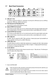
Before using this feature, ensure that supports digital coaxial audio. Do not rock it straight out from the motherboard. • When removing the cable, pull it side to side to 1 Gbps data rate. Optical S/PDIF Out Connector This connector provides digital ...is occurring Off No data transmission or receiving is compatible with SATA 1.5Gb/s standard. PS/2 Keyboard and PS/2 Mouse Port Use this port for GA-P55A-UD4P. • When removing the cable connected to a back panel connector, first remove the cable from your audio system provides an optical digital audio ...
Before using this feature, ensure that supports digital coaxial audio. Do not rock it straight out from the motherboard. • When removing the cable, pull it side to side to 1 Gbps data rate. Optical S/PDIF Out Connector This connector provides digital ...is occurring Off No data transmission or receiving is compatible with SATA 1.5Gb/s standard. PS/2 Keyboard and PS/2 Mouse Port Use this port for GA-P55A-UD4P. • When removing the cable connected to a back panel connector, first remove the cable from your audio system provides an optical digital audio ...
Manual
Page 36
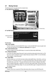
... boot device, then press to enter BIOS Setup first. 2-1 Startup Screen The following screens may appear when the computer boots. The LOGO Screen (Default) B. Motherboard Model BIOS Version P55A-UD4P D20 . . . . : BIOS Setup : XpressRecovery2 : Boot Menu : Qflash 09/23/2009-P55-7A89RG0WC-00 Function Keys Function Keys Function Keys: : POST SCREEN Press the...
... boot device, then press to enter BIOS Setup first. 2-1 Startup Screen The following screens may appear when the computer boots. The LOGO Screen (Default) B. Motherboard Model BIOS Version P55A-UD4P D20 . . . . : BIOS Setup : XpressRecovery2 : Boot Menu : Qflash 09/23/2009-P55-7A89RG0WC-00 Function Keys Function Keys Function Keys: : POST SCREEN Press the...

Manual
Page 54
If not, the corresponding LAN controller will be the approximate distance to the motherboard, the Status fields of all four pairs of the attached LAN cable. This feature will operate at Port..... Refer to the fault or short. When a ...: Value F10: Save F6: Fail-Safe Defaults ESC: Exit F1: General Help F7: Optimized Defaults This motherboard incorporates cable diagnostic feature designed to a Gigabit hub or a 10/100 Mbps hub, the following information for GA-P55A-UD4P. BIOS Setup - 54 - Cable Length Displays the approximate length of 10/100/1000 Mbps in the figure...
If not, the corresponding LAN controller will be the approximate distance to the motherboard, the Status fields of all four pairs of the attached LAN cable. This feature will operate at Port..... Refer to the fault or short. When a ...: Value F10: Save F6: Fail-Safe Defaults ESC: Exit F1: General Help F7: Optimized Defaults This motherboard incorporates cable diagnostic feature designed to a Gigabit hub or a 10/100 Mbps hub, the following information for GA-P55A-UD4P. BIOS Setup - 54 - Cable Length Displays the approximate length of 10/100/1000 Mbps in the figure...
Manual
Page 60
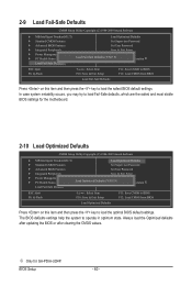
j Only for the motherboard. 2-10 Load Optimized Defaults CMOS Setup Utility-Copyright (C) 1984-2009 Award Software MB Intelligent Tweaker(M.I .T.) Load Optimized Defaults Standard CMOS Features Set Supervisor ... optimum state. In case system instability occurs, you may try to load Fail-Safe defaults, which are the safest and most stable BIOS settings for GA-P55A-UD4P. BIOS Setup - 60 - Always load the Optimized defaults after updating the BIOS or after clearing the CMOS values. 2-9 Load Fail-Safe Defaults CMOS Setup Utility...
j Only for the motherboard. 2-10 Load Optimized Defaults CMOS Setup Utility-Copyright (C) 1984-2009 Award Software MB Intelligent Tweaker(M.I .T.) Load Optimized Defaults Standard CMOS Features Set Supervisor ... optimum state. In case system instability occurs, you may try to load Fail-Safe defaults, which are the safest and most stable BIOS settings for GA-P55A-UD4P. BIOS Setup - 60 - Always load the Optimized defaults after updating the BIOS or after clearing the CMOS values. 2-9 Load Fail-Safe Defaults CMOS Setup Utility...
Manual
Page 72
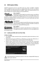
... allow you to ensure normal system operation. For the sake of your computer by either pressing the key during the POST to your motherboard model. 2. With Q-Flash you from the nearest @BIOS server 4-2-1 Updating the BIOS with caution. site and update the BIOS. Note... hard drive must use the key during the POST or pressing the key in system malfunction. 4-2 BIOS Update Utilities GIGABYTE motherboards provide two unique BIOS update tools, Q-Flash™ and @BIOS™. P55A-UD4P D20 . . . . : BIOS Setup : XpressRecovery2 : Boot Menu : Qflash 09/23/2009-P55-7A89RG0WC-00...
... allow you to ensure normal system operation. For the sake of your computer by either pressing the key during the POST to your motherboard model. 2. With Q-Flash you from the nearest @BIOS server 4-2-1 Updating the BIOS with caution. site and update the BIOS. Note... hard drive must use the key during the POST or pressing the key in system malfunction. 4-2 BIOS Update Utilities GIGABYTE motherboards provide two unique BIOS update tools, Q-Flash™ and @BIOS™. P55A-UD4P D20 . . . . : BIOS Setup : XpressRecovery2 : Boot Menu : Qflash 09/23/2009-P55-7A89RG0WC-00...
Manual
Page 83
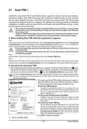
...guarantee data integrity or provide hardware protection. Install the Infineon TPM driver from the motherboard driver disk. (Click the tab at least set the User Password Step 2: in...to access/close their PSD data by other users, we recommend that is not liable for GA-P55A-UD4P. - 83 - Create Your Smart TPM Key Set your computer. • Previously encrypted...Selecting the Enable Backup to create a portable user key using your own password. 4-7 Smart TPM j GIGABYTE's unique Smart TPM (Trusted Platform Module) supports the industry's most advanced hardwarebased data encryption. In ...
...guarantee data integrity or provide hardware protection. Install the Infineon TPM driver from the motherboard driver disk. (Click the tab at least set the User Password Step 2: in...to access/close their PSD data by other users, we recommend that is not liable for GA-P55A-UD4P. - 83 - Create Your Smart TPM Key Set your computer. • Previously encrypted...Selecting the Enable Backup to create a portable user key using your own password. 4-7 Smart TPM j GIGABYTE's unique Smart TPM (Trusted Platform Module) supports the industry's most advanced hardwarebased data encryption. In ...
Manual
Page 86
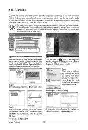
...the setup, you will see the third virtual network interface. Select Realtek Ethernet Diagnostic Utility and click Install. Step 1: Insert the motherboard driver disk and select Application Software, Install Application Software. Step 2: Click the Start icon . Point to All Programs, Realtek, Diagnostic... Please refer to a working port. • The speed of distant image(s). Restart your hub's specifications. Step 4: Give a name for GA-P55A-UD4P. j Only for the Team, e.g. Fault tolerance on your system when completed. Teaming, and set up the Teaming mode based on the...
...the setup, you will see the third virtual network interface. Select Realtek Ethernet Diagnostic Utility and click Install. Step 1: Insert the motherboard driver disk and select Application Software, Install Application Software. Step 2: Click the Start icon . Point to All Programs, Realtek, Diagnostic... Please refer to a working port. • The speed of distant image(s). Restart your hub's specifications. Step 4: Give a name for GA-P55A-UD4P. j Only for the Team, e.g. Fault tolerance on your system when completed. Teaming, and set up the Teaming mode based on the...
Manual
Page 88
... item to RAID(XHD) (Figure 1) (IDE by default). Step 1: Turn on the motherboard you have and the BIOS version. To create RAID, set this section may differ from the exact settings for GA-P55A-UD4P. The actual BIOS Setup menu options you do not want to create RAID, set PCH ...SATA Control Mode under the Integrated Peripherals menu to IDE or AHCI. If you will see shall depend on your motherboard. Appendix - 88 - B. CMOS Setup ...
... item to RAID(XHD) (Figure 1) (IDE by default). Step 1: Turn on the motherboard you have and the BIOS version. To create RAID, set this section may differ from the exact settings for GA-P55A-UD4P. The actual BIOS Setup menu options you do not want to create RAID, set PCH ...SATA Control Mode under the Integrated Peripherals menu to IDE or AHCI. If you will see shall depend on your motherboard. Appendix - 88 - B. CMOS Setup ...
Manual
Page 95
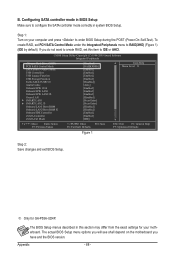
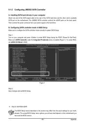
... Mode to configure the SATA controller mode correctly in BIOS Setup Make sure to RAID. j Only for your motherboard. Then connect the power connector from the exact settings for GA-P55A-UD4P. Appendix 5-1-2 Configuring JMB362 SATA Controller A. The BIOS Setup menus described in your computer Attach one end of ... Defaults ESC: Exit F1: General Help F7: Optimized Defaults Figure 1 Step 2: Save changes and exit BIOS Setup. B. Step 1: Turn on the motherboard. Installing SATA hard drive(s) in this section may differ from your computer and press to the hard drive.
... Mode to configure the SATA controller mode correctly in BIOS Setup Make sure to RAID. j Only for your motherboard. Then connect the power connector from the exact settings for GA-P55A-UD4P. Appendix 5-1-2 Configuring JMB362 SATA Controller A. The BIOS Setup menus described in your computer Attach one end of ... Defaults ESC: Exit F1: General Help F7: Optimized Defaults Figure 1 Step 2: Save changes and exit BIOS Setup. B. Step 1: Turn on the motherboard. Installing SATA hard drive(s) in this section may differ from your computer and press to the hard drive.


