
Manual
Page 1
...load the SATA controller driver first. Step 2: Install the RAID driver and operating system The X.H.D utility supports Windows 7/Vista/XP. Using GIGABYTE eXtreme Hard Drive (X.H.D) Instructions:(Note 2) Before launching X.H.D, make sure the new drive is added. Exits the X.H.D utility: Click Cancel ... with a simple click of your needs and hardware components. 3. The following procedure details the steps to set up all motherboard drivers, including the X.H.D utility. Before installing the operating system, you can go to the Application Software screen to individually ...
...load the SATA controller driver first. Step 2: Install the RAID driver and operating system The X.H.D utility supports Windows 7/Vista/XP. Using GIGABYTE eXtreme Hard Drive (X.H.D) Instructions:(Note 2) Before launching X.H.D, make sure the new drive is added. Exits the X.H.D utility: Click Cancel ... with a simple click of your needs and hardware components. 3. The following procedure details the steps to set up all motherboard drivers, including the X.H.D utility. Before installing the operating system, you can go to the Application Software screen to individually ...
Manual
Page 1
GA-P55A-UD4P GA-P55A-UD4 LGA1156 socket motherboard for Intel® Core™ i7 processor family/ Intel® Core™ i5 processor family User's Manual Rev. 1002 12ME-P55AU4P-1002R
GA-P55A-UD4P GA-P55A-UD4 LGA1156 socket motherboard for Intel® Core™ i7 processor family/ Intel® Core™ i5 processor family User's Manual Rev. 1002 12ME-P55AU4P-1002R
Manual
Page 2
Motherboard GA-P55A-UD4P/GA-P55A-UD4 Oct. 16, 2009 Motherboard GA-P55A-UD4P / GA-P55A-UD4 Oct. 16, 2009
Motherboard GA-P55A-UD4P/GA-P55A-UD4 Oct. 16, 2009 Motherboard GA-P55A-UD4P / GA-P55A-UD4 Oct. 16, 2009
Manual
Page 3
...reproduced, copied, translated, transmitted, or published in the use GIGABYTE's unique features, read or download the information on/from the Support&Downloads\Motherboard\Technology Guide page on your motherboard revision before updating motherboard BIOS, drivers, or when looking for technical information. For ...notice. For instructions on how to their respective owners. Check your motherboard looks like this product, GIGABYTE provides the following types of documentations: For quick set-up of GIGABYTE. Changes to the specifications and features in this manual are legally ...
...reproduced, copied, translated, transmitted, or published in the use GIGABYTE's unique features, read or download the information on/from the Support&Downloads\Motherboard\Technology Guide page on your motherboard revision before updating motherboard BIOS, drivers, or when looking for technical information. For ...notice. For instructions on how to their respective owners. Check your motherboard looks like this product, GIGABYTE provides the following types of documentations: For quick set-up of GIGABYTE. Changes to the specifications and features in this manual are legally ...
Manual
Page 4
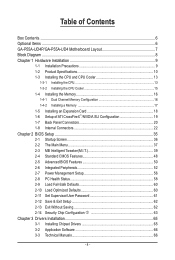
Table of Contents Box Contents...6 Optional Items...6 GA-P55A-UD4P/GA-P55A-UD4 Motherboard Layout 7 Block Diagram...8 Chapter 1 Hardware Installation 9 1-1 Installation Precautions 9 1-2 Product Specifications 10 1-3 Installing the CPU and CPU Cooler 13 1-3-1 Installing the CPU 13 1-3-2 Installing the CPU ...
Table of Contents Box Contents...6 Optional Items...6 GA-P55A-UD4P/GA-P55A-UD4 Motherboard Layout 7 Block Diagram...8 Chapter 1 Hardware Installation 9 1-1 Installation Precautions 9 1-2 Product Specifications 10 1-3 Installing the CPU and CPU Cooler 13 1-3-1 Installing the CPU 13 1-3-2 Installing the CPU ...
Manual
Page 6
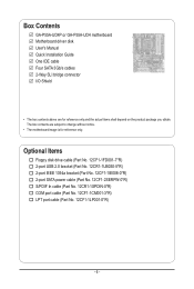
...-1SPDIN-0*R) COM port cable (Part No. 12CF1-1CM001-3*R) LPT port cable (Part No. 12CF1-1LP001-0*R) - 6 - The box contents are for reference only. Box Contents GA-P55A-UD4P or GA-P55A-UD4 motherboard Motherboard driver disk User's Manual Quick Installation Guide One IDE cable Four SATA 3Gb/s cables 2-Way SLI bridge connector I/O Shield • The box contents above...
...-1SPDIN-0*R) COM port cable (Part No. 12CF1-1CM001-3*R) LPT port cable (Part No. 12CF1-1LP001-0*R) - 6 - The box contents are for reference only. Box Contents GA-P55A-UD4P or GA-P55A-UD4 motherboard Motherboard driver disk User's Manual Quick Installation Guide One IDE cable Four SATA 3Gb/s cables 2-Way SLI bridge connector I/O Shield • The box contents above...
Manual
Page 7
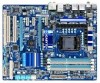
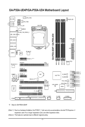
...hardware limitation, the PCIEX1_1 slot can only accommodate a shorter PCI Express x1 expansion card. GA-P55A-UD4P/GA-P55A-UD4 Motherboard Layout KB_USB R_SPDIF CPU_FAN SYS_FAN1 ATX_12V_2X4 JMB362 USB_1394_ESATA_2 USB_1394_ESATA_1 USB_LAN2 j LGA1156 PHASE LED PWR_FAN GA-P55A-UD4P / GA-P55A-UD4 DDR3_2 DDR3_1 DDR3_4 DDR3_3 USB30_LAN1 ATX F_AUDIO AUDIO NEC RTL8111D PCIEX1_1(Note 1) PCIEX16 RTL8111D ...SATA2_0 SATA2_3 SATA2_2 SATA2_5 SATA2_4 IT8720 PCI2 COMA F1_1394 LPT IDE FDD F_USB2 F_USB1 F_PANEL j Only for GA-P55A-UD4P. (Note 1) Due to different regional policy. - 7 -
...hardware limitation, the PCIEX1_1 slot can only accommodate a shorter PCI Express x1 expansion card. GA-P55A-UD4P/GA-P55A-UD4 Motherboard Layout KB_USB R_SPDIF CPU_FAN SYS_FAN1 ATX_12V_2X4 JMB362 USB_1394_ESATA_2 USB_1394_ESATA_1 USB_LAN2 j LGA1156 PHASE LED PWR_FAN GA-P55A-UD4P / GA-P55A-UD4 DDR3_2 DDR3_1 DDR3_4 DDR3_3 USB30_LAN1 ATX F_AUDIO AUDIO NEC RTL8111D PCIEX1_1(Note 1) PCIEX16 RTL8111D ...SATA2_0 SATA2_3 SATA2_2 SATA2_5 SATA2_4 IT8720 PCI2 COMA F1_1394 LPT IDE FDD F_USB2 F_USB1 F_PANEL j Only for GA-P55A-UD4P. (Note 1) Due to different regional policy. - 7 -
Manual
Page 9
... which can lead to damage to system components as well as physical harm to the user. • If you do not remove or break motherboard S/N (Serial Number) sticker or warranty sticker provided by your hands dry and first touch a metal object to eliminate static electricity. • ...Prior to installing the motherboard, please have it on top of an antistatic pad or within an electrostatic shielding container. • Before unplugging the power supply cable from...
... which can lead to damage to system components as well as physical harm to the user. • If you do not remove or break motherboard S/N (Serial Number) sticker or warranty sticker provided by your hands dry and first touch a metal object to eliminate static electricity. • ...Prior to installing the motherboard, please have it on top of an antistatic pad or within an electrostatic shielding container. • Before unplugging the power supply cable from...
Manual
Page 12
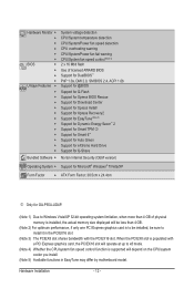
... Internet Security (OEM version) Operating System w Support for Microsoft® Windows® 7/Vista/XP Form Factor w ATX Form Factor; 30.5cm x 24.4cm j Only for GA-P55A-UD4P. (Note 1) Due to install it in EasyTune may differ by motherboard model.
... Internet Security (OEM version) Operating System w Support for Microsoft® Windows® 7/Vista/XP Form Factor w ATX Form Factor; 30.5cm x 24.4cm j Only for GA-P55A-UD4P. (Note 1) Due to install it in EasyTune may differ by motherboard model.
Manual
Page 13
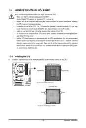
... Notch Notch Triangle Pin One Marking on the computer if the CPU cooler is not recommended that the motherboard supports the CPU. (Go to GIGABYTE's website for the peripherals. Locate the alignment keys on the motherboard CPU socket and the notches on the CPU. 1-3 Installing the CPU and CPU Cooler Read the following...
... Notch Notch Triangle Pin One Marking on the computer if the CPU cooler is not recommended that the motherboard supports the CPU. (Go to GIGABYTE's website for the peripherals. Locate the alignment keys on the motherboard CPU socket and the notches on the CPU. 1-3 Installing the CPU and CPU Cooler Read the following...
Manual
Page 14
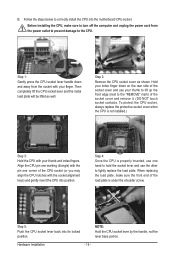
... the CPU socket (or you may align the CPU notches with your thumb and index fingers. Step 5: Push the CPU socket lever back into the motherboard CPU socket. Hardware Installation - 14 -
... the CPU socket (or you may align the CPU notches with your thumb and index fingers. Step 5: Push the CPU socket lever back into the motherboard CPU socket. Hardware Installation - 14 -
Manual
Page 15
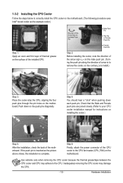
... on installing the cooler.) Step 5: After the installation, check the back of the CPU cooler to the CPU fan header (CPU_FAN) on the motherboard. Direction of the Arrow Sign on the Male Push Pin Male Push Pin The Top of Female Push Pin Female Push Pin Step 2: Before installing...the contrary, is complete. Push down each push pin. 1-3-2 Installing the CPU Cooler Follow the steps below to correctly install the CPU cooler on the motherboard. (The following procedure uses Intel® boxed cooler as the picture above shows, the installation is to install.) Step 3: Place the cooler atop the...
... on installing the cooler.) Step 5: After the installation, check the back of the CPU cooler to the CPU fan header (CPU_FAN) on the motherboard. Direction of the Arrow Sign on the Male Push Pin Male Push Pin The Top of Female Push Pin Female Push Pin Step 2: Before installing...the contrary, is complete. Push down each push pin. 1-3-2 Installing the CPU Cooler Follow the steps below to correctly install the CPU cooler on the motherboard. (The following procedure uses Intel® boxed cooler as the picture above shows, the installation is to install.) Step 3: Place the cooler atop the...
Manual
Page 16
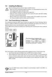
..., be enabled if only one direction. Hardware Installation - 16 - If you begin to install the memory: • Make sure that the motherboard supports the memory. If only one DDR3 memory module is installed, it in Dual Channel mode. 1. After the memory is installed. 2. When... modules have a foolproof design. It is recommended that memory of the same capacity, brand, speed, and chips be used . (Go to GIGABYTE's website for optimum performance. Enabling Dual Channel memory mode will automatically detect the specifications and capacity of the same capacity, brand, speed, and ...
..., be enabled if only one direction. Hardware Installation - 16 - If you begin to install the memory: • Make sure that the motherboard supports the memory. If only one DDR3 memory module is installed, it in Dual Channel mode. 1. After the memory is installed. 2. When... modules have a foolproof design. It is recommended that memory of the same capacity, brand, speed, and chips be used . (Go to GIGABYTE's website for optimum performance. Enabling Dual Channel memory mode will automatically detect the specifications and capacity of the same capacity, brand, speed, and ...
Manual
Page 17
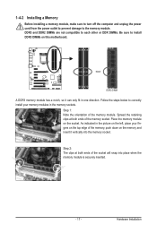
..., make sure to turn off the computer and unplug the power cord from the power outlet to prevent damage to install DDR3 DIMMs on this motherboard. As indicated in the picture on the socket. DDR3 and DDR2 DIMMs are not compatible to each other or DDR DIMMs. Be sure to the...
..., make sure to turn off the computer and unplug the power cord from the power outlet to prevent damage to install DDR3 DIMMs on this motherboard. As indicated in the picture on the socket. DDR3 and DDR2 DIMMs are not compatible to each other or DDR DIMMs. Be sure to the...
Manual
Page 18
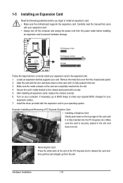
... turn off the computer and unplug the power cord from the power outlet before you begin to install an expansion card: • Make sure the motherboard supports the expansion card. Secure the card's metal bracket to the chassis back panel with the expansion card in the slot and does not rock...
... turn off the computer and unplug the power cord from the power outlet before you begin to install an expansion card: • Make sure the motherboard supports the expansion card. Secure the card's metal bracket to the chassis back panel with the expansion card in the slot and does not rock...
Manual
Page 19
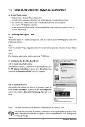
System Requirements - A CrossFireX/SLI-supported motherboard with your graphics cards for the power requirement) B. To Enable CrossFireX Function After installing the graphics card driver in the operating system, go to the ...
System Requirements - A CrossFireX/SLI-supported motherboard with your graphics cards for the power requirement) B. To Enable CrossFireX Function After installing the graphics card driver in the operating system, go to the ...
Manual
Page 20
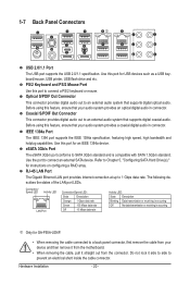
... out from the connector. Coaxial S/PDIF Out Connector This connector provides digital audio out to Chapter 5, "Configuring SATA Hard Drive(s)," for GA-P55A-UD4P. • When removing the cable connected to an external audio system that supports digital coaxial audio. Refer to an external audio... digital audio in connector. PS/2 Keyboard and PS/2 Mouse Port Use this feature, ensure that your device and then remove it from the motherboard. • When removing the cable, pull it side to side to SATA 3Gb/s standard and is occurring j Only for instructions on configuring...
... out from the connector. Coaxial S/PDIF Out Connector This connector provides digital audio out to Chapter 5, "Configuring SATA Hard Drive(s)," for GA-P55A-UD4P. • When removing the cable connected to an external audio system that supports digital coaxial audio. Refer to an external audio... digital audio in connector. PS/2 Keyboard and PS/2 Mouse Port Use this feature, ensure that your device and then remove it from the motherboard. • When removing the cable, pull it side to side to SATA 3Gb/s standard and is occurring j Only for instructions on configuring...
Manual
Page 22
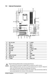
..., make sure your devices are compliant with the connectors you wish to connect. • Before installing the devices, be sure to the connector on the motherboard.
..., make sure your devices are compliant with the connectors you wish to connect. • Before installing the devices, be sure to the connector on the motherboard.
Manual
Page 23
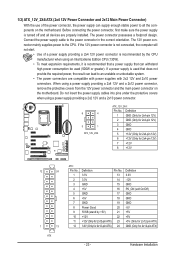
... a power supply providing a 2x4 12V and a 2x12 power connector, remove the protective covers from the 12V power connector and the main power connector on the motherboard. Definition 1 GND (Only for 2x4-pin 12V) 2 GND (Only for 2x4-pin 12V) 3 GND 4 GND 5 +12V (Only for 2x4-pin 12V) 6... a 2x10 power connector. 8 4 5 1 ATX_12V_2X4 ATX_12V_2X4: Pin No. If the 12V power connector is turned off and all the components on the motherboard. Before connecting the power connector, first make sure the power supply is not connected, the computer will not start. • Use of the power connector...
... a power supply providing a 2x4 12V and a 2x12 power connector, remove the protective covers from the 12V power connector and the main power connector on the motherboard. Definition 1 GND (Only for 2x4-pin 12V) 2 GND (Only for 2x4-pin 12V) 3 GND 4 GND 5 +12V (Only for 2x4-pin 12V) 6... a 2x10 power connector. 8 4 5 1 ATX_12V_2X4 ATX_12V_2X4: Pin No. If the 12V power connector is turned off and all the components on the motherboard. Before connecting the power connector, first make sure the power supply is not connected, the computer will not start. • Use of the power connector...
Manual
Page 24
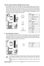
...dissipation, it is the ground wire. The fan header has a foolproof insertion design. Do not place a jumper cap on the headers. The motherboard supports CPU fan speed control, which requires the use of a CPU fan with colorcoded power connector wires. Definition 1 CPU_FAN 1 GND 2 +...: Pin No. When connecting a fan cable, be sure to connect it in the correct orientation. 3/4/5) CPU_FAN/SYS_FAN1/SYS_FAN2/PWR_FAN (Fan Headers) The motherboard has a 4-pin CPU fan header (CPU_FAN), a 4-pin (SYS_FAN2) and two 3-pin (SYS_ FAN1) system fan headers, and a 3-pin power...
...dissipation, it is the ground wire. The fan header has a foolproof insertion design. Do not place a jumper cap on the headers. The motherboard supports CPU fan speed control, which requires the use of a CPU fan with colorcoded power connector wires. Definition 1 CPU_FAN 1 GND 2 +...: Pin No. When connecting a fan cable, be sure to connect it in the correct orientation. 3/4/5) CPU_FAN/SYS_FAN1/SYS_FAN2/PWR_FAN (Fan Headers) The motherboard has a 4-pin CPU fan header (CPU_FAN), a 4-pin (SYS_FAN2) and two 3-pin (SYS_ FAN1) system fan headers, and a 3-pin power...


