
Manual
Page 1
... 1: Configure the system BIOS Enter the system BIOS Setup program, set eXtreme Hard Drive (X.H.D) under the Integrated Peripherals menu to Enabled to enable RAID for RAID 0. Step 2: Install the RAID driver and operating system The X.H.D utility supports Windows 7/Vista/XP. Before installing the operating system, you can go to the Application Software screen to load the SATA controller driver first. Or you have to individually install the X.H.D utility later. B. Exits the X.H.D utility: Click Cancel to automatically set up a RAID 0 array later using...
... 1: Configure the system BIOS Enter the system BIOS Setup program, set eXtreme Hard Drive (X.H.D) under the Integrated Peripherals menu to Enabled to enable RAID for RAID 0. Step 2: Install the RAID driver and operating system The X.H.D utility supports Windows 7/Vista/XP. Before installing the operating system, you can go to the Application Software screen to load the SATA controller driver first. Or you have to individually install the X.H.D utility later. B. Exits the X.H.D utility: Click Cancel to automatically set up a RAID 0 array later using...
Manual
Page 3
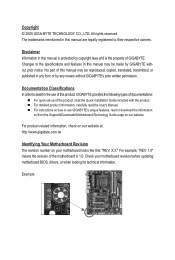
... part of GIGABYTE. For instructions on our website. Copyright © 2009 GIGA-BYTE TECHNOLOGY CO., LTD. The trademarks mentioned in the use GIGABYTE's unique features, read the User's Manual. Check your motherboard looks like this manual may be reproduced, copied, translated, transmitted, or published in this product, GIGABYTE provides the following types of documentations: For quick set-up of the product, read the Quick Installation Guide...
... part of GIGABYTE. For instructions on our website. Copyright © 2009 GIGA-BYTE TECHNOLOGY CO., LTD. The trademarks mentioned in the use GIGABYTE's unique features, read the User's Manual. Check your motherboard looks like this manual may be reproduced, copied, translated, transmitted, or published in this product, GIGABYTE provides the following types of documentations: For quick set-up of the product, read the Quick Installation Guide...
Manual
Page 4
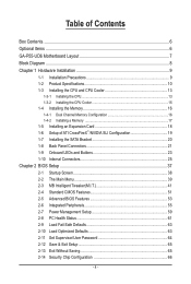
... 1-4-2 Installing a Memory 17 1-5 Installing an Expansion Card 18 1-6 Setup of ATI CrossFireX™/NVIDIA SLI Configuration 19 1-7 Installing the SATA Bracket 20 1-8 Back Panel Connectors 21 1-9 Onboard LEDs and Buttons 23 1-10 Internal Connectors 25 Chapter 2 BIOS Setup 37 2-1 Startup Screen 38 2-2 The Main Menu 39 2-3 MB Intelligent Tweaker(M.I.T 41 2-4 Standard CMOS Features 51 2-5 Advanced BIOS Features 53 2-6 Integrated Peripherals 55 2-7 Power Management Setup 59 2-8 PC Health Status 61 2-9 Load Fail-Safe Defaults 63 2-10 Load Optimized Defaults 63 2-11 Set...
... 1-4-2 Installing a Memory 17 1-5 Installing an Expansion Card 18 1-6 Setup of ATI CrossFireX™/NVIDIA SLI Configuration 19 1-7 Installing the SATA Bracket 20 1-8 Back Panel Connectors 21 1-9 Onboard LEDs and Buttons 23 1-10 Internal Connectors 25 Chapter 2 BIOS Setup 37 2-1 Startup Screen 38 2-2 The Main Menu 39 2-3 MB Intelligent Tweaker(M.I.T 41 2-4 Standard CMOS Features 51 2-5 Advanced BIOS Features 53 2-6 Integrated Peripherals 55 2-7 Power Management Setup 59 2-8 PC Health Status 61 2-9 Load Fail-Safe Defaults 63 2-10 Load Optimized Defaults 63 2-11 Set...
Manual
Page 10
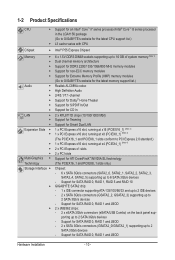
Support for SATA RAID 0, RAID 1, RAID 5 and RAID 10 GIGABYTE SATA2 chip: - 1 x IDE connector supporting ATA-133/100/66/33 and up to 2 IDE devices - 2 x SATA 3Gb/s connectors (GSATA2_2, GSATA2_3) supporting up to 2 SATA 3Gb/s devices - 1-2 Product Specifications CPU Support for an Intel® Core™ i7 series processor/Intel® Core™ i5 series processor in the LGA1156 package (Go to GIGABYTE's website for the latest CPU support list.) L3 cache varies with CPU Chipset Intel® P55 Express Chipset Memory 6...
Support for SATA RAID 0, RAID 1, RAID 5 and RAID 10 GIGABYTE SATA2 chip: - 1 x IDE connector supporting ATA-133/100/66/33 and up to 2 IDE devices - 2 x SATA 3Gb/s connectors (GSATA2_2, GSATA2_3) supporting up to 2 SATA 3Gb/s devices - 1-2 Product Specifications CPU Support for an Intel® Core™ i7 series processor/Intel® Core™ i5 series processor in the LGA1156 package (Go to GIGABYTE's website for the latest CPU support list.) L3 cache varies with CPU Chipset Intel® P55 Express Chipset Memory 6...
Manual
Page 19
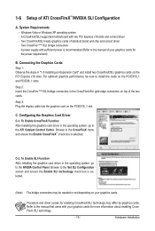
... the PCI Express x16 slots. C-2. Procedure and driver screen for the power requirement) B. Two CrossFire (Note )/SLI bridge connectors - Step 3: Plug the display cable into the graphics card on the PCIEX16_1 and PCIEX8_1 slots. Refer to the CrossFireX menu and ensure the Enable CrossFireX™ check box is selected. (Note) The bridge connectors may differ by graphics cards. 1-6 Setup of identical brand and chip and correct driver - A CrossFireX/SLI-supported motherboard with your graphics cards. C. Windows Vista or Windows...
... the PCI Express x16 slots. C-2. Procedure and driver screen for the power requirement) B. Two CrossFire (Note )/SLI bridge connectors - Step 3: Plug the display cable into the graphics card on the PCIEX16_1 and PCIEX8_1 slots. Refer to the CrossFireX menu and ensure the Enable CrossFireX™ check box is selected. (Note) The bridge connectors may differ by graphics cards. 1-6 Setup of identical brand and chip and correct driver - A CrossFireX/SLI-supported motherboard with your graphics cards. C. Windows Vista or Windows...

Manual
Page 24
... of lighted LEDs. PW_SW: Power button RST_SW: Reset button CMOS_SW: Clearing CMOS button • Always turn on/off your computer and unplug the power cord from the power outlet before clearing the CMOS values. • After system restart, go to BIOS Setup to load factory defaults (select Load Optimized Defaults) or manually configure the BIOS settings (refer to Chapter 4, "Dynamic Energy Saver™ 2," for BIOS configurations). Hardware Installation - 24 - The higher the CPU loading, the more details. Quick Buttons This motherboard...
... of lighted LEDs. PW_SW: Power button RST_SW: Reset button CMOS_SW: Clearing CMOS button • Always turn on/off your computer and unplug the power cord from the power outlet before clearing the CMOS values. • After system restart, go to BIOS Setup to load factory defaults (select Load Optimized Defaults) or manually configure the BIOS settings (refer to Chapter 4, "Dynamic Energy Saver™ 2," for BIOS configurations). Hardware Installation - 24 - The higher the CPU loading, the more details. Quick Buttons This motherboard...
Manual
Page 27
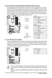
.... • These fan headers are designed with fan speed control design. The black connector wire is recommended that a system fan be sure to this header. The motherboard supports CPU fan speed control, which requires the use of a CPU fan with colorcoded power connector wires. Definition 1 1 GND SYS_FAN2 2 +12V / Speed Control 3 Sense 4 Reserve SYS_FAN1/SYS_FAN3/PWR_FAN: Pin No. The fan header has a foolproof insertion design. Hardware Installation When connecting a fan cable, be installed inside the chassis. Do not place a jumper cap on the headers. - 27 -
.... • These fan headers are designed with fan speed control design. The black connector wire is recommended that a system fan be sure to this header. The motherboard supports CPU fan speed control, which requires the use of a CPU fan with colorcoded power connector wires. Definition 1 1 GND SYS_FAN2 2 +12V / Speed Control 3 Sense 4 Reserve SYS_FAN1/SYS_FAN3/PWR_FAN: Pin No. The fan header has a foolproof insertion design. Hardware Installation When connecting a fan cable, be installed inside the chassis. Do not place a jumper cap on the headers. - 27 -

Manual
Page 40
... CPU, memory, etc. Standard CMOS Features Use this menu to configure the system time and date, hard drive types, floppy disk drive types, and the type of errors that stop the system boot, etc. Advanced BIOS Features Use this menu to configure the device boot order, advanced features available on the CPU, and the primary display adapter. Integrated Peripherals Use this menu to configure all peripheral devices, such as IDE, SATA, USB, integrated audio, and integrated LAN, etc. Power Management Setup Use...
... CPU, memory, etc. Standard CMOS Features Use this menu to configure the system time and date, hard drive types, floppy disk drive types, and the type of errors that stop the system boot, etc. Advanced BIOS Features Use this menu to configure the device boot order, advanced features available on the CPU, and the primary display adapter. Integrated Peripherals Use this menu to configure all peripheral devices, such as IDE, SATA, USB, integrated audio, and integrated LAN, etc. Power Management Setup Use...

Manual
Page 43
... supports this feature. Auto lets the BIOS automatically configure this setting. (Default: Auto) CPU Thermal Monitor (Note) Enables or disables Intel CPU Thermal Monitor function, a CPU overheating protection function. The item is adjustable only if a CPU with unlocked clock ratio is overheated. Note: If your system fails to boot after overclocking, please wait for 20 seconds to allow for automated system reboot, or clear the CMOS values to reset the board to default...
... supports this feature. Auto lets the BIOS automatically configure this setting. (Default: Auto) CPU Thermal Monitor (Note) Enables or disables Intel CPU Thermal Monitor function, a CPU overheating protection function. The item is adjustable only if a CPU with unlocked clock ratio is overheated. Note: If your system fails to boot after overclocking, please wait for 20 seconds to allow for automated system reboot, or clear the CMOS values to reset the board to default...
Manual
Page 50
... the CPU and Chipset. (Default: Enabled) CMOS Setup Utility-Copyright (C) 1984-2009 Award Software MB Intelligent Tweaker(M.I.T.) } M.I.T Current Status } Advanced Frequency Settings } Advanced Memory Settings } Advanced Voltage Settings } Miscellaneous Settings [Press Enter] [Press Enter] [Press Enter] [Press Enter] [Press Enter] Item Help Menu Level BIOS Version BCLK CPU Frequency Memory Frequency Total Memory Size D15 133.27 MHz 3198.42 MHz 1332.80 MHz 1024 MB CPU Temperature PCH Temperature 45oC 40oC Vcore DRAM Voltage...
... the CPU and Chipset. (Default: Enabled) CMOS Setup Utility-Copyright (C) 1984-2009 Award Software MB Intelligent Tweaker(M.I.T.) } M.I.T Current Status } Advanced Frequency Settings } Advanced Memory Settings } Advanced Voltage Settings } Miscellaneous Settings [Press Enter] [Press Enter] [Press Enter] [Press Enter] [Press Enter] Item Help Menu Level BIOS Version BCLK CPU Frequency Memory Frequency Total Memory Size D15 133.27 MHz 3198.42 MHz 1332.80 MHz 1024 MB CPU Temperature PCH Temperature 45oC 40oC Vcore DRAM Voltage...
Manual
Page 53
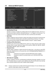
... third party hardware monitor utility is installed. (Default: Disabled) (Note) This item is present only if you enter BIOS Setup. Use the up or down arrow key to select a device and press to move it up or down on the list. 2-5 Advanced BIOS Features CMOS Setup Utility-Copyright (C) 1984-2009 Award Software Advanced BIOS Features } Hard Disk Boot Priority Quick Boot First Boot Device Second Boot Device Third Boot Device Password Check HDD S.M.A.R.T. Options are: Floppy, LS120, Hard Disk, CDROM, ZIP, USB-FDD, USB-ZIP, USB-CDROM, USB-HDD, Legacy LAN, Disabled.
... third party hardware monitor utility is installed. (Default: Disabled) (Note) This item is present only if you enter BIOS Setup. Use the up or down arrow key to select a device and press to move it up or down on the list. 2-5 Advanced BIOS Features CMOS Setup Utility-Copyright (C) 1984-2009 Award Software Advanced BIOS Features } Hard Disk Boot Priority Quick Boot First Boot Device Second Boot Device Third Boot Device Password Check HDD S.M.A.R.T. Options are: Floppy, LS120, Hard Disk, CDROM, ZIP, USB-FDD, USB-ZIP, USB-CDROM, USB-HDD, Legacy LAN, Disabled.

Manual
Page 55
... Setup Utility-Copyright (C) 1984-2009 Award Software Integrated Peripherals SATA RAID/AHCI Mode SATA Port0-3 Native Mode USB Controllers USB Legacy Function USB Storage Function Azalia Codec PCI Express x4/x1 Slot Onboard H/W 1394 Onboard H/W LAN1 Onboard H/W LAN2 Green LAN } SMART LAN1 } SMART LAN2 Onboard LAN1 Boot ROM Onboard LAN2 Boot ROM eSATA Controller eSATA Ctrl Mode GSATA 0_1 Controller GSATA 0_1 Ctrl Mode [Disabled] [Enabled] [Enabled] [Enabled] [Enabled] [Auto] [Auto] [Enabled] [Enabled] [Enabled] [Disabled] [Press Enter...
... Setup Utility-Copyright (C) 1984-2009 Award Software Integrated Peripherals SATA RAID/AHCI Mode SATA Port0-3 Native Mode USB Controllers USB Legacy Function USB Storage Function Azalia Codec PCI Express x4/x1 Slot Onboard H/W 1394 Onboard H/W LAN1 Onboard H/W LAN2 Green LAN } SMART LAN1 } SMART LAN2 Onboard LAN1 Boot ROM Onboard LAN2 Boot ROM eSATA Controller eSATA Ctrl Mode GSATA 0_1 Controller GSATA 0_1 Ctrl Mode [Disabled] [Enabled] [Enabled] [Enabled] [Enabled] [Auto] [Auto] [Enabled] [Enabled] [Enabled] [Disabled] [Press Enter...
Manual
Page 58
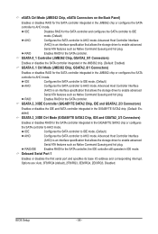
... plug. the IDE controller still operates in the JMB362 chip or configures the SATA controller to AHCI mode. Options are: Auto, 3F8/IRQ4 (default), 2F8/IRQ3, 3E8/IRQ4, 2E8/IRQ3, Disabled. GSATA 2_3/IDE Controller (GIGABYTE SATA2 Chip, IDE and GSATA2_2/3 Connectors) Enables or disables the IDE and SATA controller integrated in the GIGABYTE SATA2 chip. (Default: Enabled) GSATA 2_3/IDE Ctrl Mode (GIGABYTE SATA2 Chip, IDE and GSATA2_2/3 Connectors) Enables or disables RAID for the SATA controller integrated in the JMB362 chip or configures the SATA controller to AHCI mode. Onboard Serial Port...
... plug. the IDE controller still operates in the JMB362 chip or configures the SATA controller to AHCI mode. Options are: Auto, 3F8/IRQ4 (default), 2F8/IRQ3, 3E8/IRQ4, 2E8/IRQ3, Disabled. GSATA 2_3/IDE Controller (GIGABYTE SATA2 Chip, IDE and GSATA2_2/3 Connectors) Enables or disables the IDE and SATA controller integrated in the GIGABYTE SATA2 chip. (Default: Enabled) GSATA 2_3/IDE Ctrl Mode (GIGABYTE SATA2 Chip, IDE and GSATA2_2/3 Connectors) Enables or disables RAID for the SATA controller integrated in the JMB362 chip or configures the SATA controller to AHCI mode. Onboard Serial Port...
Manual
Page 59
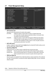
... the computer in a low power mode. 2-7 Power Management Setup CMOS Setup Utility-Copyright (C) 1984-2009 Award Software Power Management Setup ACPI Suspend Type ACPI LED Control Soft-Off by PWR-BTTN PME Event Wake Up Power On by Ring Resume by a wake-up signal from a PCI or PCIe device. In S1 sleep state, the system appears suspended and stays in MS-DOS mode using the power button. Instant-Off Press the power button and then the system will enter suspend mode.
... the computer in a low power mode. 2-7 Power Management Setup CMOS Setup Utility-Copyright (C) 1984-2009 Award Software Power Management Setup ACPI Suspend Type ACPI LED Control Soft-Off by PWR-BTTN PME Event Wake Up Power On by Ring Resume by a wake-up signal from a PCI or PCIe device. In S1 sleep state, the system appears suspended and stays in MS-DOS mode using the power button. Instant-Off Press the power button and then the system will enter suspend mode.
Manual
Page 62
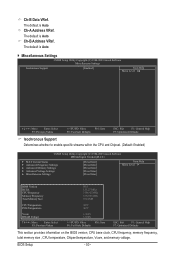
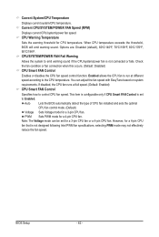
... Voltage mode can adjust the fan speed with EasyTune based on system requirements. Current System/CPU Temperature Displays current system/CPU temperature. Options are: Disabled (default), 60oC/140oF, 70oC/158oF, 80oC/176oF, 90oC/194oF. Enabled allows the CPU fan to run at full speed. (Default: Enabled) CPU Smart FAN Control Specifies how to Enabled. BIOS Setup - 62 - PWM Sets PWM mode for a 3-pin CPU fan. If disabled, the CPU fan runs at different speed according to emit warning sound if the CPU/system/power fan is set for a 3-pin CPU fan or a 4-pin CPU fan...
... Voltage mode can adjust the fan speed with EasyTune based on system requirements. Current System/CPU Temperature Displays current system/CPU temperature. Options are: Disabled (default), 60oC/140oF, 70oC/158oF, 80oC/176oF, 90oC/194oF. Enabled allows the CPU fan to run at full speed. (Default: Enabled) CPU Smart FAN Control Specifies how to Enabled. BIOS Setup - 62 - PWM Sets PWM mode for a 3-pin CPU fan. If disabled, the CPU fan runs at different speed according to emit warning sound if the CPU/system/power fan is set for a 3-pin CPU fan or a 4-pin CPU fan...

Manual
Page 95
... cable to the rear of the SATA hard drive and the other end to the hard drive. In BIOS Setup, go to RAID/IDE CMOS Setup Utility-Copyright (C) 1984-2009 Award Software Integrated Peripherals USB Legacy Function USB Storage Function Azalia Codec PCI Express x4/x1 Slot Onboard H/W 1394 Onboard H/W LAN1 Onboard H/W LAN2 Green LAN } SMART LAN1 } SMART LAN2 Onboard LAN1 Boot ROM Onboard LAN2 Boot ROM eSATA Controller eSATA Ctrl Mode GSATA 0_1 Controller GSATA 0_1 Ctrl Mode GSATA 2_3/IDE Controller GSATA 2_3/IDE Ctrl Mode Onboard Serial Port...
... cable to the rear of the SATA hard drive and the other end to the hard drive. In BIOS Setup, go to RAID/IDE CMOS Setup Utility-Copyright (C) 1984-2009 Award Software Integrated Peripherals USB Legacy Function USB Storage Function Azalia Codec PCI Express x4/x1 Slot Onboard H/W 1394 Onboard H/W LAN1 Onboard H/W LAN2 Green LAN } SMART LAN1 } SMART LAN2 Onboard LAN1 Boot ROM Onboard LAN2 Boot ROM eSATA Controller eSATA Ctrl Mode GSATA 0_1 Controller GSATA 0_1 Ctrl Mode GSATA 2_3/IDE Controller GSATA 2_3/IDE Ctrl Mode Onboard Serial Port...
Manual
Page 101
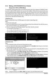
... automatically copy the driver files to a USB flash drive. Press any key to exit when finished. (Note) Figure 4 Figure 3 Change the directory from \32bit to \64bit if you also can copy the SATA controller driver from the motherboard driver disk to the floppy disk. Appendix For installing Windows Vista, you wish to a floppy disk. For example, from the motherboard driver disk to copy the Windows 64-bit driver. - 101 - Without the driver, the hard drive may not be...
... automatically copy the driver files to a USB flash drive. Press any key to exit when finished. (Note) Figure 4 Figure 3 Change the directory from \32bit to \64bit if you also can copy the SATA controller driver from the motherboard driver disk to the floppy disk. Appendix For installing Windows Vista, you wish to a floppy disk. For example, from the motherboard driver disk to copy the Windows 64-bit driver. - 101 - Without the driver, the hard drive may not be...
Manual
Page 103
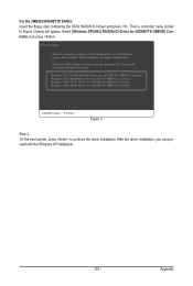
... a controller menu similar to the previous screen. (Windows XP/2003) RAID/AHCI Driver for GIGABYTE GBB36X Controller (Windows 2000) RAID Driver for GIGABYTE GBB363 Controller (Windows 2000) AHCI Driver for GIGABYTE GBB363 Controller (Windows 2000) RAID Driver for use with the Windows XP installation. - 103 - Windows Setup You have chosen to configure a SCSI Adapter for GIGABYTE GBB360 Controller ENTER=Select F3=Exit Figure 3 Step 3: On the next screen, press to continue the driver installation. Select the SCSI Adapter you can proceed with Windows, using a device support disk...
... a controller menu similar to the previous screen. (Windows XP/2003) RAID/AHCI Driver for GIGABYTE GBB36X Controller (Windows 2000) RAID Driver for GIGABYTE GBB363 Controller (Windows 2000) AHCI Driver for GIGABYTE GBB363 Controller (Windows 2000) RAID Driver for use with the Windows XP installation. - 103 - Windows Setup You have chosen to configure a SCSI Adapter for GIGABYTE GBB360 Controller ENTER=Select F3=Exit Figure 3 Step 3: On the next screen, press to continue the driver installation. Select the SCSI Adapter you can proceed with Windows, using a device support disk...
Manual
Page 121
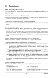
...: Keyboard error 2 short: CMOS setting error 1 long, 9 short: BIOS ROM error 1 long, 1 short: Memory or motherboard error Continuous long beeps: Graphics card not inserted properly 1 long, 2 short: Monitor or graphics card error Continuous short beeps: Power error - 121 - Then make sure Service Pack 1 or Service Pack 2 has been installed (check in the BIOS Setup program. For motherboards that have a clearing CMOS jumper, refer to the instructions on the motherboard battery in Chapter 1 to short the jumper to clear the CMOS values. Q: What do I install the onboard HD...
...: Keyboard error 2 short: CMOS setting error 1 long, 9 short: BIOS ROM error 1 long, 1 short: Memory or motherboard error Continuous long beeps: Graphics card not inserted properly 1 long, 2 short: Monitor or graphics card error Continuous short beeps: Power error - 121 - Then make sure Service Pack 1 or Service Pack 2 has been installed (check in the BIOS Setup program. For motherboards that have a clearing CMOS jumper, refer to the instructions on the motherboard battery in Chapter 1 to short the jumper to clear the CMOS values. Q: What do I install the onboard HD...
Manual
Page 126
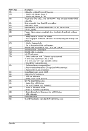
... chipset power management hook 2. USB final Initialization 2. Invoke all IDE devices: HDD, LS120, ZIP, CDROM... not until this POST stage can users enter the CMOS setup utility Reset keyboard is Early_Reset_KB is pressed to CMOS Initialize ISA PnP boot devices 1. Initialize floppy controller 2. Recover the text fond used by EPA logo (not for password Save all data in 40:hardware Detect & install all ISA adapter ROMs 2. If password is set to all PCI ROMs (except VGA) 1. Switch screen back to PCI devices...
... chipset power management hook 2. USB final Initialization 2. Invoke all IDE devices: HDD, LS120, ZIP, CDROM... not until this POST stage can users enter the CMOS setup utility Reset keyboard is Early_Reset_KB is pressed to CMOS Initialize ISA PnP boot devices 1. Initialize floppy controller 2. Recover the text fond used by EPA logo (not for password Save all data in 40:hardware Detect & install all ISA adapter ROMs 2. If password is set to all PCI ROMs (except VGA) 1. Switch screen back to PCI devices...


