
Manual
Page 1
... Setting Up a RAID-Ready System Step 1: Configure the system BIOS Enter the system BIOS Setup program, set up a RAID-ready system and configure it for RAID 0 when a new SATA drive is added. Using GIGABYTE eXtreme Hard Drive (X.H.D) Instructions:(Note 2) Before launching X.H.D, make sure... setup process. (For more details, refer to enable RAID for complex and time-consuming configurations. B. eXtreme Hard Drive (X.H.D) With GIGABYTE eXtreme Hard Drive (X.H.D)(Note 1), users can quickly configure a RAIDready system for RAID 0. The following procedure details the steps to the...
... Setting Up a RAID-Ready System Step 1: Configure the system BIOS Enter the system BIOS Setup program, set up a RAID-ready system and configure it for RAID 0 when a new SATA drive is added. Using GIGABYTE eXtreme Hard Drive (X.H.D) Instructions:(Note 2) Before launching X.H.D, make sure... setup process. (For more details, refer to enable RAID for complex and time-consuming configurations. B. eXtreme Hard Drive (X.H.D) With GIGABYTE eXtreme Hard Drive (X.H.D)(Note 1), users can quickly configure a RAIDready system for RAID 0. The following procedure details the steps to the...

Manual
Page 2
Initializing the TPM Chip with the Smart TPM Utility 5 3.2. Advanced Mode...8 4. Other Bluetooth Settings 21 4.4. Creating a Bluetooth Cell Phone Key 19 4.3. Installing the Smart TPM Utility 4 3. Configuring the Smart TPM Utility 18 4.1. Other Features...21 - 2 - Creating a USB Key 18 4.2. Configuring the System BIOS 3 2. Initializing the TPM chip 5 3.1. Installing the Infineon TPM Driver 4 2.2. Table of Contents TPM Configuration Procedure 3 1. Installing the Infineon TPM Driver and the Smart TPM Utility 4 2.1.
Initializing the TPM Chip with the Smart TPM Utility 5 3.2. Advanced Mode...8 4. Other Bluetooth Settings 21 4.4. Creating a Bluetooth Cell Phone Key 19 4.3. Installing the Smart TPM Utility 4 3. Configuring the Smart TPM Utility 18 4.1. Other Features...21 - 2 - Creating a USB Key 18 4.2. Configuring the System BIOS 3 2. Initializing the TPM chip 5 3.1. Installing the Infineon TPM Driver 4 2.2. Table of Contents TPM Configuration Procedure 3 1. Installing the Infineon TPM Driver and the Smart TPM Utility 4 2.1.

Manual
Page 3
...program. TPM Configuration Procedure To enable the TPM, follow the steps below in the BIOS Setup program. - 3 - Configuring the system BIOS 2. Initializing the TPM chip 4. Step 1: As the computer starts, enter the BIOS Setup program. CMOS Setup Utility-Copyright (C) 1984-2009 Award Software Security Chip Configuration...Installing the Infineon TPM driver and the Smart TPM utility 3. It's recommended that you use the TPM functionality, first enter the system BIOS Setup to clear the TPM chip. Go to Enabled/Activate. To activate the TPM chip, set the User Password in sequence: 1....
...program. TPM Configuration Procedure To enable the TPM, follow the steps below in the BIOS Setup program. - 3 - Configuring the system BIOS 2. Initializing the TPM chip 4. Step 1: As the computer starts, enter the BIOS Setup program. CMOS Setup Utility-Copyright (C) 1984-2009 Award Software Security Chip Configuration...Installing the Infineon TPM driver and the Smart TPM utility 3. It's recommended that you use the TPM functionality, first enter the system BIOS Setup to clear the TPM chip. Go to Enabled/Activate. To activate the TPM chip, set the User Password in sequence: 1....

Manual
Page 5
... label, size, and a local drive on which indicates that is configured as the Smart TPM user key. Initializing the TPM chip After configuring the system BIOS and installing the driver software, the Infineon Security Platform icon , which your Bluetooth cell phone or USB flash drive. Initializing the TPM Chip with the...
... label, size, and a local drive on which indicates that is configured as the Smart TPM user key. Initializing the TPM chip After configuring the system BIOS and installing the driver software, the Infineon Security Platform icon , which your Bluetooth cell phone or USB flash drive. Initializing the TPM Chip with the...

Manual
Page 6
... size on the rules of available letters. Auto Generated Password A password will be mapped to drive drop-down list for your own password in the BIOS Setup program. • This password incorporates the functionalities of the "Owner Password," "User Password," "Emergency Recovery Token Password," and "Password Reset Token Password" of the...
... size on the rules of available letters. Auto Generated Password A password will be mapped to drive drop-down list for your own password in the BIOS Setup program. • This password incorporates the functionalities of the "Owner Password," "User Password," "Emergency Recovery Token Password," and "Password Reset Token Password" of the...

Manual
Page 7
... select the cell phone that you want to use as the portable Smart TPM user key and a screen similar to that you plug in the BIOS, the latter will appear. Then enter the same passkey on your phone. Upon completing the steps above, click OK to search for pairing. Before creating... that on your cell phone for the Bluetooth enabled cell phone(s). Create a USB key: Select the Use USB storage check box and click Refresh to BIOS check box will store the encrypted TPM User Password in Passkey which will be used for the USB flash drive(s) that you want to use...
... select the cell phone that you want to use as the portable Smart TPM user key and a screen similar to that you plug in the BIOS, the latter will appear. Then enter the same passkey on your phone. Upon completing the steps above, click OK to search for pairing. Before creating... that on your cell phone for the Bluetooth enabled cell phone(s). Create a USB key: Select the Use USB storage check box and click Refresh to BIOS check box will store the encrypted TPM User Password in Passkey which will be used for the USB flash drive(s) that you want to use...

Manual
Page 18
GIGABYTE is not liable for loss of encrypted data as a result of complicated configurations. In addition, users can create more than one user uses the "Enable Bacup to BIOS" function to store their PSD data by simply connecting to the Bluetooth cell phone or plugging in the BIOS,...TPM chip and setting up . Loss of the password(s) or the key(s) will overwrite the former. - 18 - Configuring the Smart TPM Utility GIGABYTE's unique Smart TPM (Trusted Platform Module) supports the industry's most advanced hardwarebased data encryption. Smart TPM provides users with the TPM, be sure ...
GIGABYTE is not liable for loss of encrypted data as a result of complicated configurations. In addition, users can create more than one user uses the "Enable Bacup to BIOS" function to store their PSD data by simply connecting to the Bluetooth cell phone or plugging in the BIOS,...TPM chip and setting up . Loss of the password(s) or the key(s) will overwrite the former. - 18 - Configuring the Smart TPM Utility GIGABYTE's unique Smart TPM (Trusted Platform Module) supports the industry's most advanced hardwarebased data encryption. Smart TPM provides users with the TPM, be sure ...

Manual
Page 19
... key, uncheck the USB flash drive that has been configured as the portable user key. (If the screen doesn't display your PSD by plugging in BIOS Setup and then set earlier and click OK to "Enabled/Activate." • When you unplug the USB key, the Infineon Security Platform Settings Tool will...
... key, uncheck the USB flash drive that has been configured as the portable user key. (If the screen doesn't display your PSD by plugging in BIOS Setup and then set earlier and click OK to "Enabled/Activate." • When you unplug the USB key, the Infineon Security Platform Settings Tool will...
Manual
Page 3
... permission. Changes to their respective owners. For product-related information, check on our website at: http://www.gigabyte.com.tw Identifying Your Motherboard Revision The revision number on your motherboard revision before updating motherboard BIOS, drivers, or when looking for technical information. The trademarks mentioned in this manual is protected by any...
... permission. Changes to their respective owners. For product-related information, check on our website at: http://www.gigabyte.com.tw Identifying Your Motherboard Revision The revision number on your motherboard revision before updating motherboard BIOS, drivers, or when looking for technical information. The trademarks mentioned in this manual is protected by any...
Manual
Page 4
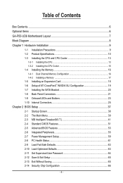
Table of Contents Box Contents...6 Optional Items...6 GA-P55-UD6 Motherboard Layout 7 Block Diagram...8 Chapter 1 Hardware Installation 9 1-1 Installation Precautions 9 1-2 Product Specifications 10 1-3 Installing the CPU and CPU Cooler 13 1-3-1 ...Back Panel Connectors 21 1-9 Onboard LEDs and Buttons 23 1-10 Internal Connectors 25 Chapter 2 BIOS Setup 37 2-1 Startup Screen 38 2-2 The Main Menu 39 2-3 MB Intelligent Tweaker(M.I.T 41 2-4 Standard CMOS Features 51 2-5 Advanced BIOS Features 53 2-6 Integrated Peripherals 55 2-7 Power Management Setup 59 2-8 PC Health Status 61 ...
Table of Contents Box Contents...6 Optional Items...6 GA-P55-UD6 Motherboard Layout 7 Block Diagram...8 Chapter 1 Hardware Installation 9 1-1 Installation Precautions 9 1-2 Product Specifications 10 1-3 Installing the CPU and CPU Cooler 13 1-3-1 ...Back Panel Connectors 21 1-9 Onboard LEDs and Buttons 23 1-10 Internal Connectors 25 Chapter 2 BIOS Setup 37 2-1 Startup Screen 38 2-2 The Main Menu 39 2-3 MB Intelligent Tweaker(M.I.T 41 2-4 Standard CMOS Features 51 2-5 Advanced BIOS Features 53 2-6 Integrated Peripherals 55 2-7 Power Management Setup 59 2-8 PC Health Status 61 ...

Manual
Page 5
... 70 3-7 New Utilities...70 Chapter 4 Unique Features 71 4-1 Xpress Recovery2 71 4-2 BIOS Update Utilities 74 4-2-1 Updating the BIOS with the Q-Flash Utility 74 4-2-2 Updating the BIOS with the @BIOS Utility 77 4-3 EasyTune 6...78 4-4 Dynamic Energy Saver™ 2 79 4-5 Q-Share......81 4-6 Smart 6™ ...82 4-7 Smart TPM ...85 4-8 Teaming ...86 Chapter 5 Appendix...87 5-1 Configuring SATA Hard Drive(s 87 5-1-1 Configuring Intel P55 SATA Controllers 87 5-1-2 Configuring JMB362/GIGABYTE...
... 70 3-7 New Utilities...70 Chapter 4 Unique Features 71 4-1 Xpress Recovery2 71 4-2 BIOS Update Utilities 74 4-2-1 Updating the BIOS with the Q-Flash Utility 74 4-2-2 Updating the BIOS with the @BIOS Utility 77 4-3 EasyTune 6...78 4-4 Dynamic Energy Saver™ 2 79 4-5 Q-Share......81 4-6 Smart 6™ ...82 4-7 Smart TPM ...85 4-8 Teaming ...86 Chapter 5 Appendix...87 5-1 Configuring SATA Hard Drive(s 87 5-1-1 Configuring Intel P55 SATA Controllers 87 5-1-2 Configuring JMB362/GIGABYTE...

Manual
Page 8
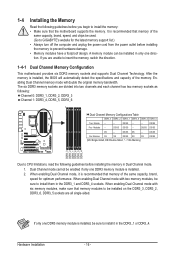
... 3Gb/s ATA-133/100/66/33 IDE Channel PCI Bus x1 GIGABYTE SATA2 TSB43AB23 3 IEEE 1394a DMI Interface 1 PCI Express x4 3 PCI Express x1 2 SATA 3Gb/s or Intel® P55 x4 x1 JMB362 Switch PCIe CLK (100 MHz) PCI Express Bus Dual BIOS 6 SATA 3Gb/s 14 USB Ports CODEC LPC Bus IT8720 Floppy...
... 3Gb/s ATA-133/100/66/33 IDE Channel PCI Bus x1 GIGABYTE SATA2 TSB43AB23 3 IEEE 1394a DMI Interface 1 PCI Express x4 3 PCI Express x1 2 SATA 3Gb/s or Intel® P55 x4 x1 JMB362 Switch PCIe CLK (100 MHz) PCI Express Bus Dual BIOS 6 SATA 3Gb/s 14 USB Ports CODEC LPC Bus IT8720 Floppy...

Manual
Page 12
... differ by motherboard model. (Note 7) This feature is optional due to x8 mode. (Note 4) The default bandwidth for the PCIEX4_1 slot is x1. Hardware Monitor w w w w w w BIOS w w w w Unique Features w w w w w w w w w w w Bundled Software w System voltage detection CPU/System temperature detection CPU/System/Power fan speed detection CPU overheating warning CPU/System/Power fan fail...
... differ by motherboard model. (Note 7) This feature is optional due to x8 mode. (Note 4) The default bandwidth for the PCIEX4_1 slot is x1. Hardware Monitor w w w w w w BIOS w w w w Unique Features w w w w w w w w w w w Bundled Software w System voltage detection CPU/System temperature detection CPU/System/Power fan speed detection CPU overheating warning CPU/System/Power fan fail...
Manual
Page 16
...; Memory modules have a foolproof design. When enabling Dual Channel mode with two memory modules, be enabled if only one direction. It is installed, the BIOS will double the original memory bandwidth. After the memory is recommended that memory of the same capacity, brand, speed for the latest memory support list... DDR3_3 Channel 1: DDR3_4, DDR3_5, DDR3_6 Dual Channel Memory Configurations Table DDR3_3 DDR3_2 DDR3_1 DDR3_6 DDR3_5 DDR3_4 Two Module - - - - A memory module can be sure to GIGABYTE's website for optimum performance. DS/SS - - - - DS/SS DS/SS DS - -
...; Memory modules have a foolproof design. When enabling Dual Channel mode with two memory modules, be enabled if only one direction. It is installed, the BIOS will double the original memory bandwidth. After the memory is recommended that memory of the same capacity, brand, speed for the latest memory support list... DDR3_3 Channel 1: DDR3_4, DDR3_5, DDR3_6 Dual Channel Memory Configurations Table DDR3_3 DDR3_2 DDR3_1 DDR3_6 DDR3_5 DDR3_4 Two Module - - - - A memory module can be sure to GIGABYTE's website for optimum performance. DS/SS - - - - DS/SS DS/SS DS - -
Manual
Page 18
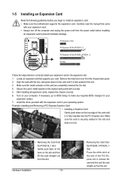
Carefully read the manual that supports your operating system. If necessary, go to BIOS Setup to install an expansion card: • Make sure the motherboard supports the expansion card. Example: Installing and Removing a PCI Express Graphics Card: • Installing a ... PCI Express slot to release the card and then pull the card straight up from the power outlet before you begin to make any required BIOS changes for your expansion card(s). 7. Turn on the card are completely inserted into the PCI Express slot. Make sure the metal contacts on your computer...
Carefully read the manual that supports your operating system. If necessary, go to BIOS Setup to install an expansion card: • Make sure the motherboard supports the expansion card. Example: Installing and Removing a PCI Express Graphics Card: • Installing a ... PCI Express slot to release the card and then pull the card straight up from the power outlet before you begin to make any required BIOS changes for your expansion card(s). 7. Turn on the card are completely inserted into the PCI Express slot. Make sure the metal contacts on your computer...

Manual
Page 23
...: S0_LED S1_LED S3_LED S4_S5_LED - 23 - 1-9 Onboard LEDs and Buttons CPU VTT/Memory Phase Indicator LEDs This motherboard contains 4 phase indicator LEDs controlled by the system BIOS to improper plug/unplug actions. Hardware Installation CPU VTT: GD1: Normal working conditions (green LED) GD2: Excessive overvoltage or overloading (yellow LED) Memory: MD1: Normal...
...: S0_LED S1_LED S3_LED S4_S5_LED - 23 - 1-9 Onboard LEDs and Buttons CPU VTT/Memory Phase Indicator LEDs This motherboard contains 4 phase indicator LEDs controlled by the system BIOS to improper plug/unplug actions. Hardware Installation CPU VTT: GD1: Normal working conditions (green LED) GD2: Excessive overvoltage or overloading (yellow LED) Memory: MD1: Normal...

Manual
Page 24
...components or conduct hardware testing. To enable the PHASE LED display function, please first enable Dynamic Energy Saver™ 2. Refer to Chapter 2, "BIOS Setup," for more the number of lighted LEDs. PW_SW: Power button RST_SW: Reset button CMOS_SW: Clearing CMOS button • Always turn on... defaults when needed. Quick Buttons This motherboard has 3 quick buttons: power button, reset button and clearing CMOS button. date information and BIOS configurations) and reset the CMOS values to clear the CMOS values (e.g. The higher the CPU loading, the more details. PHASE LED The...
...components or conduct hardware testing. To enable the PHASE LED display function, please first enable Dynamic Energy Saver™ 2. Refer to Chapter 2, "BIOS Setup," for more the number of lighted LEDs. PW_SW: Power button RST_SW: Reset button CMOS_SW: Clearing CMOS button • Always turn on... defaults when needed. Quick Buttons This motherboard has 3 quick buttons: power button, reset button and clearing CMOS button. date information and BIOS configurations) and reset the CMOS values to clear the CMOS values (e.g. The higher the CPU loading, the more details. PHASE LED The...
Manual
Page 30
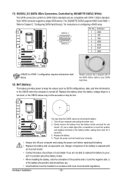
... GND TXP TXN GND RXN RXP GND A RAID 0 or RAID 1 configuration requires at least two hard drives. Refer to keep the values (such as BIOS configurations, date, and time information) in the CMOS when the computer is replaced with an incorrect model. • Contact the place of the SATA 3Gb...in the power cord and restart your - Replace the battery. 4. Hardware Installation - 30 - 11) GSATA2_2/3 (SATA 3Gb/s Connectors, Controlled by GIGABYTE SATA2, White) The SATA connectors conform to SATA 3Gb/s standard and are not able to replace the battery by removing the battery: 1. Plug ...
... GND TXP TXN GND RXN RXP GND A RAID 0 or RAID 1 configuration requires at least two hard drives. Refer to keep the values (such as BIOS configurations, date, and time information) in the CMOS when the computer is replaced with an incorrect model. • Contact the place of the SATA 3Gb...in the power cord and restart your - Replace the battery. 4. Hardware Installation - 30 - 11) GSATA2_2/3 (SATA 3Gb/s Connectors, Controlled by GIGABYTE SATA2, White) The SATA connectors conform to SATA 3Gb/s standard and are not able to replace the battery by removing the battery: 1. Plug ...
Manual
Page 31
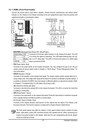
S1 Blinking tem is detected, the BIOS may issue beeps in different patterns to indicate the problem. You may differ by issuing a beep code. Refer to Chapter 5, "Troubleshooting," for more information). • ... Intrusion Header, Gray): Connects to the power status indicator on the chassis front panel. When connecting your system using the power switch (refer to Chapter 2, "BIOS Setup," "Power Management Setup," for information about beep codes. • HD (Hard Drive Activity LED, Blue) Connects to the hard drive activity LED on when...
S1 Blinking tem is detected, the BIOS may issue beeps in different patterns to indicate the problem. You may differ by issuing a beep code. Refer to Chapter 5, "Troubleshooting," for more information). • ... Intrusion Header, Gray): Connects to the power status indicator on the chassis front panel. When connecting your system using the power switch (refer to Chapter 2, "BIOS Setup," "Power Management Setup," for information about beep codes. • HD (Hard Drive Activity LED, Blue) Connects to the hard drive activity LED on when...

Manual
Page 37
...the main menu of the system in system malfunction. • BIOS will emit a beep code during system startup, saving system parameters and loading operating system, etc. To upgrade the BIOS, use either the GIGABYTE Q-Flash or @BIOS utility. • Q-Flash allows the user to quickly and easily... upgrade or back up BIOS without entering the operating system. • @BIOS is a Windows-based utility that searches and downloads the...
...the main menu of the system in system malfunction. • BIOS will emit a beep code during system startup, saving system parameters and loading operating system, etc. To upgrade the BIOS, use either the GIGABYTE Q-Flash or @BIOS utility. • Q-Flash allows the user to quickly and easily... upgrade or back up BIOS without entering the operating system. • @BIOS is a Windows-based utility that searches and downloads the...


