
Manual
Page 1
...Operating System." ) Step 3: Install the motherboard drivers and the X.H.D utiltiy After installing the operating system, insert the motherboard driver disk. To automatically set up a RAID 0 array: Click Auto to automatically and quickly set up a RAID 0 array. 2. Using GIGABYTE eXtreme Hard Drive (X.H.D) Instructions:(Note 2) ...the RAID-ready system drive. (To add a new hard drive into the array to expand its capacity. eXtreme Hard Drive (X.H.D) With GIGABYTE eXtreme Hard Drive (X.H.D)(Note 1), users can use X.H.D to easily add a hard drive into a RAID 0 array that's been created ...
...Operating System." ) Step 3: Install the motherboard drivers and the X.H.D utiltiy After installing the operating system, insert the motherboard driver disk. To automatically set up a RAID 0 array: Click Auto to automatically and quickly set up a RAID 0 array. 2. Using GIGABYTE eXtreme Hard Drive (X.H.D) Instructions:(Note 2) ...the RAID-ready system drive. (To add a new hard drive into the array to expand its capacity. eXtreme Hard Drive (X.H.D) With GIGABYTE eXtreme Hard Drive (X.H.D)(Note 1), users can use X.H.D to easily add a hard drive into a RAID 0 array that's been created ...

Manual
Page 4
... the right of the drivers that the Infineon TPM driver and the Smart TPM utility have been installed. 2.1. Installing the Infineon TPM Driver Insert the GIGABYTE motherboard driver disk. Installing the Infineon TPM Driver and the Smart TPM Utility Before you 'll be directed to install the Infineon TPM driver and the... Install button on the "Xpress Install" main menu to the Install New Utilities menu. "Xpress Install" will install all of Smart TPM to install. Some motherboard driver disks include the Smart TPM utility in "Xpress Install."
... the right of the drivers that the Infineon TPM driver and the Smart TPM utility have been installed. 2.1. Installing the Infineon TPM Driver Insert the GIGABYTE motherboard driver disk. Installing the Infineon TPM Driver and the Smart TPM Utility Before you 'll be directed to install the Infineon TPM driver and the... Install button on the "Xpress Install" main menu to the Install New Utilities menu. "Xpress Install" will install all of Smart TPM to install. Some motherboard driver disks include the Smart TPM utility in "Xpress Install."

Manual
Page 7
... Passkey which will store the encrypted TPM User Password in the BIOS, the latter will appear. Before creating a Bluetooth cell phone key, make sure your motherboard includes a Bluetooth receiver and turn on the search and Bluetooth functions on the left will overwrite the former. 2. Upon completing the steps above, click OK...
... Passkey which will store the encrypted TPM User Password in the BIOS, the latter will appear. Before creating a Bluetooth cell phone key, make sure your motherboard includes a Bluetooth receiver and turn on the search and Bluetooth functions on the left will overwrite the former. 2. Upon completing the steps above, click OK...

Manual
Page 19
...'t display your Bluetooth-enabled cell phone, click Refresh to let Smart TPM re-detect the device.) Before creating a Bluetooth cell phone key, make sure your motherboard includes a Bluetooth receiver and turn off or reset your phone. - 19 - Then the USB key is normal. When prompted to confirm, click Yes. Do not...
...'t display your Bluetooth-enabled cell phone, click Refresh to let Smart TPM re-detect the device.) Before creating a Bluetooth cell phone key, make sure your motherboard includes a Bluetooth receiver and turn off or reset your phone. - 19 - Then the USB key is normal. When prompted to confirm, click Yes. Do not...
Manual
Page 1
GA-P55-UD6 LGA1156 socket motherboard for Intel® Core™ i7 processor family/ Intel® Core™ i5 processor family User's Manual Rev. 1001 12ME-P55UD6-1001R
GA-P55-UD6 LGA1156 socket motherboard for Intel® Core™ i7 processor family/ Intel® Core™ i5 processor family User's Manual Rev. 1001 12ME-P55UD6-1001R
Manual
Page 3
... check on our website at: http://www.gigabyte.com.tw Identifying Your Motherboard Revision The revision number on our website. Check your motherboard looks like this manual may be made by GIGABYTE without GIGABYTE's prior written permission. Documentation Classifications In order ...the information on/from the Support&Downloads\Motherboard\Technology Guide page on your motherboard revision before updating motherboard BIOS, drivers, or when looking for technical information. No part of this manual are legally registered to use GIGABYTE's unique features, read the User's Manual...
... check on our website at: http://www.gigabyte.com.tw Identifying Your Motherboard Revision The revision number on our website. Check your motherboard looks like this manual may be made by GIGABYTE without GIGABYTE's prior written permission. Documentation Classifications In order ...the information on/from the Support&Downloads\Motherboard\Technology Guide page on your motherboard revision before updating motherboard BIOS, drivers, or when looking for technical information. No part of this manual are legally registered to use GIGABYTE's unique features, read the User's Manual...
Manual
Page 4
Table of Contents Box Contents...6 Optional Items...6 GA-P55-UD6 Motherboard Layout 7 Block Diagram...8 Chapter 1 Hardware Installation 9 1-1 Installation Precautions 9 1-2 Product Specifications 10 1-3 Installing the CPU and CPU Cooler 13 1-3-1 Installing the CPU 13 1-3-2 Installing the CPU ...
Table of Contents Box Contents...6 Optional Items...6 GA-P55-UD6 Motherboard Layout 7 Block Diagram...8 Chapter 1 Hardware Installation 9 1-1 Installation Precautions 9 1-2 Product Specifications 10 1-3 Installing the CPU and CPU Cooler 13 1-3-1 Installing the CPU 13 1-3-2 Installing the CPU ...
Manual
Page 6
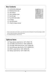
... power cable (Part No. 12CF1-2SERPW-0*R) S/PDIF In cable (Part No. 12CR1-1SPDIN-0*R) COM port cable (Part No. 12CF1-1CM001-3*R) - 6 - Box Contents GA-P55-UD6 motherboard Motherboard driver disk User's Manual Quick Installation Guide One IDE cable Four SATA 3Gb/s cables I/O Shield One SATA bracket 2-Way SLI bridge connector • The box... contents above are subject to change without notice. • The motherboard image is for reference only and the actual items shall depend on the product package you obtain.
... power cable (Part No. 12CF1-2SERPW-0*R) S/PDIF In cable (Part No. 12CR1-1SPDIN-0*R) COM port cable (Part No. 12CF1-1CM001-3*R) - 6 - Box Contents GA-P55-UD6 motherboard Motherboard driver disk User's Manual Quick Installation Guide One IDE cable Four SATA 3Gb/s cables I/O Shield One SATA bracket 2-Way SLI bridge connector • The box... contents above are subject to change without notice. • The motherboard image is for reference only and the actual items shall depend on the product package you obtain.
Manual
Page 7
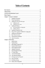
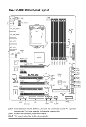
GA-P55-UD6 Motherboard Layout KB_USB R_SPDIF SYS_FAN3 ATX_12V_2X USB_1394_ESATA_2 LGA1156 CPU_FAN PW_SW USB_1394_ESATA_1 USB_LAN2 USB_LAN1 JMB362 F_AUDIO AUDIO PCIEX1_1 (Note 1) RTL8111D PCH_FAN RTL8111D PCIEX1_2 Intel® P55 PCIEX16_1 CODEC CD_IN SPDIF_I PCI1 PCIEX8_1 GA-P55-UD6 BATTERY TPM IC (Note 3) B_BIOS M_BIOS... SPDIF_O PCI2 ACPI LED TSB43AB23 DDR3_3 DDR3_2 DDR3_1 DDR3_6 DDR3_5 DDR3_4 MD1 MD2 ATX GD1 GD2 PWR_FAN PHASE LED SYS_FAN1 JMB362 GIGABYTE SATA2 ...
GA-P55-UD6 Motherboard Layout KB_USB R_SPDIF SYS_FAN3 ATX_12V_2X USB_1394_ESATA_2 LGA1156 CPU_FAN PW_SW USB_1394_ESATA_1 USB_LAN2 USB_LAN1 JMB362 F_AUDIO AUDIO PCIEX1_1 (Note 1) RTL8111D PCH_FAN RTL8111D PCIEX1_2 Intel® P55 PCIEX16_1 CODEC CD_IN SPDIF_I PCI1 PCIEX8_1 GA-P55-UD6 BATTERY TPM IC (Note 3) B_BIOS M_BIOS... SPDIF_O PCI2 ACPI LED TSB43AB23 DDR3_3 DDR3_2 DDR3_1 DDR3_6 DDR3_5 DDR3_4 MD1 MD2 ATX GD1 GD2 PWR_FAN PHASE LED SYS_FAN1 JMB362 GIGABYTE SATA2 ...
Manual
Page 9
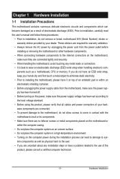
... follow these procedures: • Prior to installation, do not allow screws to come in a high-temperature environment. • Turning on the motherboard, make sure the power supply voltage has been set according to the local voltage standard. • Before using the product, please verify that ... has been turned off. • Before turning on the power, make sure they are connected tightly and securely. • When handling the motherboard, avoid touching any installation steps or have a problem related to the use of electrostatic discharge (ESD). ponents such as a result of the ...
... follow these procedures: • Prior to installation, do not allow screws to come in a high-temperature environment. • Turning on the motherboard, make sure the power supply voltage has been set according to the local voltage standard. • Before using the product, please verify that ... has been turned off. • Before turning on the power, make sure they are connected tightly and securely. • When handling the motherboard, avoid touching any installation steps or have a problem related to the use of electrostatic discharge (ESD). ponents such as a result of the ...

Manual
Page 12
... PCIEX1_2 slots and the eSATA connectors will become unavailable because they share band width with the PCIEX16_1 slot. When it in EasyTune may differ by motherboard model. (Note 7) This feature is x1. Hardware Monitor w w w w w w BIOS w w w w Unique Features w w w w w w w w w w w Bundled Software w System voltage detection CPU/System temperature detection CPU/System/Power fan speed...
... PCIEX1_2 slots and the eSATA connectors will become unavailable because they share band width with the PCIEX16_1 slot. When it in EasyTune may differ by motherboard model. (Note 7) This feature is x1. Hardware Monitor w w w w w w BIOS w w w w Unique Features w w w w w w w w w w w Bundled Software w System voltage detection CPU/System temperature detection CPU/System/Power fan speed...

Manual
Page 13
... does not meet the standard requirements for the peripherals. Locate the alignment keys on the motherboard CPU socket and the notches on the CPU - 13 - It is not recommended that the motherboard supports the CPU. (Go to GIGABYTE's website for the latest CPU support list.) • Always turn on the surface of the...
... does not meet the standard requirements for the peripherals. Locate the alignment keys on the motherboard CPU socket and the notches on the CPU - 13 - It is not recommended that the motherboard supports the CPU. (Go to GIGABYTE's website for the latest CPU support list.) • Always turn on the surface of the...

Manual
Page 14
....) Step 3: Hold the CPU with your thumb and index finger to lightly replace the load plate. Step 5: Push the CPU socket lever back into the motherboard CPU socket. Hardware Installation - 14 -
....) Step 3: Hold the CPU with your thumb and index finger to lightly replace the load plate. Step 5: Push the CPU socket lever back into the motherboard CPU socket. Hardware Installation - 14 -

Manual
Page 15
... CPU. Check that the Male and Female push pins are joined closely. (Refer to your CPU cooler installation manual for instructions on the motherboard. If the push pin is inserted as the example cooler.) Step 1: Apply an even and thin layer of thermal grease on the surface...installation, check the back of the installed CPU. 1-3-2 Installing the CPU Cooler Follow the steps below to correctly install the CPU cooler on the motherboard. (The following procedure uses Intel® boxed cooler as the picture above shows, the installation is to install.) Step 3: Place the cooler ...
... CPU. Check that the Male and Female push pins are joined closely. (Refer to your CPU cooler installation manual for instructions on the motherboard. If the push pin is inserted as the example cooler.) Step 1: Apply an even and thin layer of thermal grease on the surface...installation, check the back of the installed CPU. 1-3-2 Installing the CPU Cooler Follow the steps below to correctly install the CPU cooler on the motherboard. (The following procedure uses Intel® boxed cooler as the picture above shows, the installation is to install.) Step 3: Place the cooler ...
Manual
Page 16
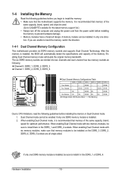
...channel has two memory sockets as following guidelines before installing the memory in only one DDR3 memory module is installed, be used. (Go to GIGABYTE's website for optimum performance. DS/SS DS/SS - - DS/SS DS - - When enabling Dual Channel mode with two memory modules,... before installing the memory to prevent hardware damage. • Memory modules have a foolproof design. After the memory is recommended that the motherboard supports the memory. Enabling Dual Channel memory mode will automatically detect the specifications and capacity of the same capacity, brand, speed, and ...
...channel has two memory sockets as following guidelines before installing the memory in only one DDR3 memory module is installed, be used. (Go to GIGABYTE's website for optimum performance. DS/SS DS/SS - - DS/SS DS - - When enabling Dual Channel mode with two memory modules,... before installing the memory to prevent hardware damage. • Memory modules have a foolproof design. After the memory is recommended that the motherboard supports the memory. Enabling Dual Channel memory mode will automatically detect the specifications and capacity of the same capacity, brand, speed, and ...

Manual
Page 17
... memory module has a notch, so it vertically into place when the memory module is securely inserted. - 17 - Hardware Installation Place the memory module on this motherboard. DDR3 and DDR2 DIMMs are not compatible to each other or DDR DIMMs. Be sure to the memory module. As indicated in the picture on...
... memory module has a notch, so it vertically into place when the memory module is securely inserted. - 17 - Hardware Installation Place the memory module on this motherboard. DDR3 and DDR2 DIMMs are not compatible to each other or DDR DIMMs. Be sure to the memory module. As indicated in the picture on...
Manual
Page 18
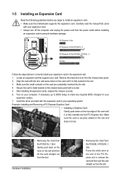
... the card until it is securely seated in the slot. 3. If necessary, go to BIOS Setup to install an expansion card: • Make sure the motherboard supports the expansion card. Example: Installing and Removing a PCI Express Graphics Card: • Installing a Graphics Card: Gently push down on the card until it is...
... the card until it is securely seated in the slot. 3. If necessary, go to BIOS Setup to install an expansion card: • Make sure the motherboard supports the expansion card. Example: Installing and Removing a PCI Express Graphics Card: • Installing a Graphics Card: Gently push down on the card until it is...
Manual
Page 19
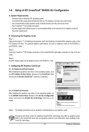
... to the NVIDIA Control Panel. Step 3: Plug the display cable into the graphics card on the PCIEX16_1 and PCIEX8_1 slots. Hardware Installation A CrossFireX/SLI-supported motherboard with sufficient power is selected. C-2. Connecting the Graphics Cards Step 1: Observe the steps in the CrossFireX/SLI gold edge connectors on your graphics cards for...
... to the NVIDIA Control Panel. Step 3: Plug the display cable into the graphics card on the PCIEX16_1 and PCIEX8_1 slots. Hardware Installation A CrossFireX/SLI-supported motherboard with sufficient power is selected. C-2. Connecting the Graphics Cards Step 1: Observe the steps in the CrossFireX/SLI gold edge connectors on your graphics cards for...

Manual
Page 20
... panel with a screw. 1-7 Installing the SATA Bracket The SATA bracket allows you only need to turn off your system and the power switch on your motherboard. Step 2: Connect the SATA cable from the bracket to your system by expanding the internal SATA port(s) to the chassis back panel. • Turn off...
... panel with a screw. 1-7 Installing the SATA Bracket The SATA bracket allows you only need to turn off your system and the power switch on your motherboard. Step 2: Connect the SATA cable from the bracket to your system by expanding the internal SATA port(s) to the chassis back panel. • Turn off...
Manual
Page 21
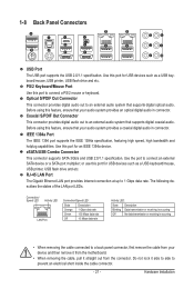
.../mouse, USB printer, USB flash drive and etc. Use the port to an external audio system that your device and then remove it from the motherboard. • When removing the cable, pull it side to side to 1 Gbps data rate. 1-8 Back Panel Connectors USB Port The USB port supports the USB...
.../mouse, USB printer, USB flash drive and etc. Use the port to an external audio system that your device and then remove it from the motherboard. • When removing the cable, pull it side to side to 1 Gbps data rate. 1-8 Back Panel Connectors USB Port The USB port supports the USB...


