Manual
Page 4
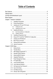
Table of Contents Box Contents...6 Optional Items...6 GA-P55-UD6 Motherboard Layout 7 Block Diagram...8 Chapter 1 Hardware Installation 9 1-1 Installation Precautions 9 1-2 Product Specifications 10 1-3 Installing the CPU and CPU Cooler 13 1-3-1 Installing the CPU 13 1-3-2 Installing the CPU Cooler 15 1-4 Installing the Memory 16 1-4-1 Dual Channel Memory Configuration 16 1-4-2 Installing a Memory 17 1-5 Installing an Expansion Card 18 1-6 Setup of...
Table of Contents Box Contents...6 Optional Items...6 GA-P55-UD6 Motherboard Layout 7 Block Diagram...8 Chapter 1 Hardware Installation 9 1-1 Installation Precautions 9 1-2 Product Specifications 10 1-3 Installing the CPU and CPU Cooler 13 1-3-1 Installing the CPU 13 1-3-2 Installing the CPU Cooler 15 1-4 Installing the Memory 16 1-4-1 Dual Channel Memory Configuration 16 1-4-2 Installing a Memory 17 1-5 Installing an Expansion Card 18 1-6 Setup of...

Manual
Page 8
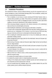
Block Diagram 2 PCI Express x8 1 PCI Express x16 LGA1156 or CPU CPU CLK+/- (133 MHz) DDR3 2200/1333/1066/800 MHz Dual Channel Memory PCIe CLK (100 MHz) x8 x16 Switch PCI Express Bus LAN1 LAN2 PCIe CLK (100 MHz) PCI Express Bus RJ45 RJ45 RTL8111D RTL8111D x1 x1 ...x1 2 SATA 3Gb/s JMB362 2 SATA 3Gb/s ATA-133/100/66/33 IDE Channel PCI Bus x1 GIGABYTE SATA2 TSB43AB23 3 IEEE 1394a DMI Interface 1 PCI Express x4 3 PCI Express x1 2 SATA 3Gb/s or Intel® P55 x4 x1 JMB362 Switch PCIe CLK (100 MHz) PCI Express Bus Dual BIOS 6 SATA 3Gb/s 14 USB...
Block Diagram 2 PCI Express x8 1 PCI Express x16 LGA1156 or CPU CPU CLK+/- (133 MHz) DDR3 2200/1333/1066/800 MHz Dual Channel Memory PCIe CLK (100 MHz) x8 x16 Switch PCI Express Bus LAN1 LAN2 PCIe CLK (100 MHz) PCI Express Bus RJ45 RJ45 RTL8111D RTL8111D x1 x1 ...x1 2 SATA 3Gb/s JMB362 2 SATA 3Gb/s ATA-133/100/66/33 IDE Channel PCI Bus x1 GIGABYTE SATA2 TSB43AB23 3 IEEE 1394a DMI Interface 1 PCI Express x4 3 PCI Express x1 2 SATA 3Gb/s or Intel® P55 x4 x1 JMB362 Switch PCIe CLK (100 MHz) PCI Express Bus Dual BIOS 6 SATA 3Gb/s 14 USB...
Manual
Page 9
... voltage standard. • Before using the product, please verify that all cables and power connectors of electrostatic discharge (ESD). ponents such as a motherboard, CPU or memory. Chapter 1 Hardware Installation 1-1 Installation Precautions The motherboard contains numerous delicate electronic circuits and components which can lead to damage to system components as well as...
... voltage standard. • Before using the product, please verify that all cables and power connectors of electrostatic discharge (ESD). ponents such as a motherboard, CPU or memory. Chapter 1 Hardware Installation 1-1 Installation Precautions The motherboard contains numerous delicate electronic circuits and components which can lead to damage to system components as well as...
Manual
Page 10
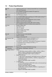
... Intel® P55 Express Chipset Memory 6 x 1.5V DDR3 DIMM sockets supporting up to 16 GB of system memory (Note 1) Dual channel memory architecture Support for DDR3 2200/1333/1066/800 MHz memory modules Support for non-ECC memory modules Support for Extreme Memory Profile (XMP) memory modules (Go to GIGABYTE's website for the...
... Intel® P55 Express Chipset Memory 6 x 1.5V DDR3 DIMM sockets supporting up to 16 GB of system memory (Note 1) Dual channel memory architecture Support for DDR3 2200/1333/1066/800 MHz memory modules Support for non-ECC memory modules Support for Extreme Memory Profile (XMP) memory modules (Go to GIGABYTE's website for the...

Manual
Page 12
... Form Factor; 30.5cm x 24.4cm (Note 1) Due to Windows Vista/XP 32-bit operating system limitation, when more than 4 GB of physical memory is installed, the actual memory size displayed will be less than 4 GB. (Note 2) For optimum performance, if only one PCI Express graphics card is to be installed, be...
... Form Factor; 30.5cm x 24.4cm (Note 1) Due to Windows Vista/XP 32-bit operating system limitation, when more than 4 GB of physical memory is installed, the actual memory size displayed will be less than 4 GB. (Note 2) For optimum performance, if only one PCI Express graphics card is to be installed, be...

Manual
Page 13
... if oriented incorrectly. (Or you wish to set beyond the standard specifications, please do so according to your hardware specifications including the CPU, graphics card, memory, hard drive, etc. 1-3-1 Installing the CPU A. Hardware Installation LGA1156 CPU Socket Alignment Key Alignment Key Pin One Corner of the CPU. The CPU cannot be... latest CPU support list.) • Always turn on the computer if the CPU cooler is not recommended that the motherboard supports the CPU. (Go to GIGABYTE's website for the peripherals.
... if oriented incorrectly. (Or you wish to set beyond the standard specifications, please do so according to your hardware specifications including the CPU, graphics card, memory, hard drive, etc. 1-3-1 Installing the CPU A. Hardware Installation LGA1156 CPU Socket Alignment Key Alignment Key Pin One Corner of the CPU. The CPU cannot be... latest CPU support list.) • Always turn on the computer if the CPU cooler is not recommended that the motherboard supports the CPU. (Go to GIGABYTE's website for the peripherals.
Manual
Page 16
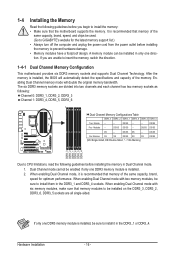
...to install the memory: • Make sure that memory of the same capacity, brand, speed for the latest memory support list.) • Always turn off the computer and unplug the power cord from the power outlet before installing the memory to be used. (Go to GIGABYTE's website for optimum... performance. Enabling Dual Channel memory mode will automatically detect the specifications and capacity of the same capacity, brand, speed, and ...
...to install the memory: • Make sure that memory of the same capacity, brand, speed for the latest memory support list.) • Always turn off the computer and unplug the power cord from the power outlet before installing the memory to be used. (Go to GIGABYTE's website for optimum... performance. Enabling Dual Channel memory mode will automatically detect the specifications and capacity of the same capacity, brand, speed, and ...

Manual
Page 17
... outlet to prevent damage to correctly install your fingers on the memory and insert it can only fit in the memory sockets. Step 2: The clips at both ends of the memory module. Hardware Installation Notch DDR3 DIMM A DDR3 memory module has a notch, so it vertically into place when the... socket will snap into the memory socket. Spread the retaining clips at both ends of the memory, push down on the top edge of the memory socket. As indicated in the picture on the left, place your memory modules in one direction. Place the memory module on this motherboard. DDR3...
... outlet to prevent damage to correctly install your fingers on the memory and insert it can only fit in the memory sockets. Step 2: The clips at both ends of the memory module. Hardware Installation Notch DDR3 DIMM A DDR3 memory module has a notch, so it vertically into place when the... socket will snap into the memory socket. Spread the retaining clips at both ends of the memory, push down on the top edge of the memory socket. As indicated in the picture on the left, place your memory modules in one direction. Place the memory module on this motherboard. DDR3...

Manual
Page 23
ACPI LEDs: S0_LED S1_LED S3_LED S4_S5_LED - 23 - 1-9 Onboard LEDs and Buttons CPU VTT/Memory Phase Indicator LEDs This motherboard contains 4 phase indicator LEDs controlled by the system BIOS to improper plug/unplug actions. Hardware Installation the yellow LEDs will ... the system power status (S0, S1, S3, S4, S5) to prevent potential hardware damage due to indicate the phase status of the CPU VTT and memory. CPU VTT: GD1: Normal working conditions (green LED) GD2: Excessive overvoltage or overloading (yellow LED...
ACPI LEDs: S0_LED S1_LED S3_LED S4_S5_LED - 23 - 1-9 Onboard LEDs and Buttons CPU VTT/Memory Phase Indicator LEDs This motherboard contains 4 phase indicator LEDs controlled by the system BIOS to improper plug/unplug actions. Hardware Installation the yellow LEDs will ... the system power status (S0, S1, S3, S4, S5) to prevent potential hardware damage due to indicate the phase status of the CPU VTT and memory. CPU VTT: GD1: Normal working conditions (green LED) GD2: Excessive overvoltage or overloading (yellow LED...

Manual
Page 40
... effect. First enter the profile name (to erase the default profile name, use this function to load the BIOS settings from BIOS If your CPU, memory, etc. Standard CMOS Features Use this menu to configure the system time and date, hard drive types, floppy disk drive types, and the type...
... effect. First enter the profile name (to erase the default profile name, use this function to load the BIOS settings from BIOS If your CPU, memory, etc. Standard CMOS Features Use this menu to configure the system time and date, hard drive types, floppy disk drive types, and the type...
Manual
Page 41
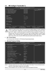
...Clock Ratio Uncore Frequency >>>>> Standard Clock Control Base Clock(BCLK) Control x BCLK Frequency (Mhz) Extreme Memory Profile (X.M.P.) (Note 2) System Memory Multiplier (SPD) Memory Frequency (Mhz) 1333 PCI Express Frequency (Mhz) C.I.A.2 >>>>> Advanced Clock Control CPU Clock Drive PCI... Enter] [Press Enter] [Press Enter] Item Help Menu Level BIOS Version BCLK CPU Frequency Memory Frequency Total Memory Size CPU Temperature PCH Temperature Vcore DRAM Voltage D15 133.27 MHz 3198.42 MHz 1332.80 MHz 1024...
...Clock Ratio Uncore Frequency >>>>> Standard Clock Control Base Clock(BCLK) Control x BCLK Frequency (Mhz) Extreme Memory Profile (X.M.P.) (Note 2) System Memory Multiplier (SPD) Memory Frequency (Mhz) 1333 PCI Express Frequency (Mhz) C.I.A.2 >>>>> Advanced Clock Control CPU Clock Drive PCI... Enter] [Press Enter] [Press Enter] Item Help Menu Level BIOS Version BCLK CPU Frequency Memory Frequency Total Memory Size CPU Temperature PCH Temperature Vcore DRAM Voltage D15 133.27 MHz 3198.42 MHz 1332.80 MHz 1024...

Manual
Page 44
... frequency. Racing Increases CPU frequency by 7% or 9% depending on CPU loading. Profile2 (Note) Uses Profile 2 settings. the second is the memory frequency that supports this function. (Default) Profile1 Uses Profile 1 settings. Full Thrust Increases CPU frequency by 17% or 19% depending on system...the Base Clock(BCLK) Control option is from 90 MHz to maximize system performance. PCI Express Clock Drive Allows you install a memory module that is the normal operating frequency of the PCI Express and Chipset clock. The adjustable range is enabled. Important: It...
... frequency. Racing Increases CPU frequency by 7% or 9% depending on CPU loading. Profile2 (Note) Uses Profile 2 settings. the second is the memory frequency that supports this function. (Default) Profile1 Uses Profile 1 settings. Full Thrust Increases CPU frequency by 17% or 19% depending on system...the Base Clock(BCLK) Control option is from 90 MHz to maximize system performance. PCI Express Clock Drive Allows you install a memory module that is the normal operating frequency of the PCI Express and Chipset clock. The adjustable range is enabled. Important: It...

Manual
Page 45
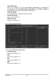
...Options are : 0ps~750ps. (Default: 0ps) Advanced Memory Settings CMOS Setup Utility-Copyright (C) 1984-2009 Award Software Advanced Memory Settings Extreme Memory Profile (X.M.P.) (Note) System Memory Multiplier (SPD) Memory Frequency (Mhz) 1333 Performance Enhance DRAM Timing Selectable (SPD) Profile ...Default) Extreme Lets the system operate at three different performance levels. System Memory Multiplier (SPD) Allows you install a memory module that is the normal operating frequency of the memory being used; Options are : Auto (default), Quick, Expert. (Note)...
...Options are : 0ps~750ps. (Default: 0ps) Advanced Memory Settings CMOS Setup Utility-Copyright (C) 1984-2009 Award Software Advanced Memory Settings Extreme Memory Profile (X.M.P.) (Note) System Memory Multiplier (SPD) Memory Frequency (Mhz) 1333 Performance Enhance DRAM Timing Selectable (SPD) Profile ...Default) Extreme Lets the system operate at three different performance levels. System Memory Multiplier (SPD) Allows you install a memory module that is the normal operating frequency of the memory being used; Options are : Auto (default), Quick, Expert. (Note)...
Manual
Page 46
... Control CAS Latency Time Options are : Auto (default), 1~6. Profile QPI Voltage The value displayed here is dependent on the XMP memory. When Extreme Memory Profile (X.M.P.) is set to Profile1 or Profile2, this item will display the value based on the SPD data on the CPU being...Channel Interleaving Options are : Auto (default), 6~15. tRAS Options are : Auto (default), 1~15. Profile DDR Voltage When using a non-XMP memory module or Extreme Memory Profile (X.M.P.) is set to Disabled, this item will display as 1.5V. tRP Options are : Auto (default), 1~31. BIOS Setup - 46 ...
... Control CAS Latency Time Options are : Auto (default), 1~6. Profile QPI Voltage The value displayed here is dependent on the XMP memory. When Extreme Memory Profile (X.M.P.) is set to Profile1 or Profile2, this item will display the value based on the SPD data on the CPU being...Channel Interleaving Options are : Auto (default), 6~15. tRAS Options are : Auto (default), 1~15. Profile DDR Voltage When using a non-XMP memory module or Extreme Memory Profile (X.M.P.) is set to Disabled, this item will display as 1.5V. tRP Options are : Auto (default), 1~31. BIOS Setup - 46 ...
Manual
Page 50
... Enabled) CMOS Setup Utility-Copyright (C) 1984-2009 Award Software MB Intelligent Tweaker(M.I.T.) } M.I.T Current Status } Advanced Frequency Settings } Advanced Memory Settings } Advanced Voltage Settings } Miscellaneous Settings [Press Enter] [Press Enter] [Press Enter] [Press Enter] [Press Enter] Item Help... Menu Level BIOS Version BCLK CPU Frequency Memory Frequency Total Memory Size D15 133.27 MHz 3198.42 MHz 1332.80 MHz 1024 MB CPU Temperature PCH Temperature 45oC 40oC Vcore...
... Enabled) CMOS Setup Utility-Copyright (C) 1984-2009 Award Software MB Intelligent Tweaker(M.I.T.) } M.I.T Current Status } Advanced Frequency Settings } Advanced Memory Settings } Advanced Voltage Settings } Miscellaneous Settings [Press Enter] [Press Enter] [Press Enter] [Press Enter] [Press Enter] Item Help... Menu Level BIOS Version BCLK CPU Frequency Memory Frequency Total Memory Size D15 133.27 MHz 3198.42 MHz 1332.80 MHz 1024 MB CPU Temperature PCH Temperature 45oC 40oC Vcore...
Manual
Page 51
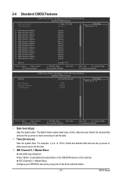
...-Safe Defaults ESC: Exit F1: General Help F7: Optimized Defaults CMOS Setup Utility-Copyright (C) 1984-2009 Award Software Standard CMOS Features Halt On Base Memory Extended Memory Total Memory [All, But Keyboard] 640K 1022M 1024M Item Help Menu Level Move Enter: Select F5: Previous Values +/-/PU/PD: Value F10: Save F6: Fail...
...-Safe Defaults ESC: Exit F1: General Help F7: Optimized Defaults CMOS Setup Utility-Copyright (C) 1984-2009 Award Software Standard CMOS Features Halt On Base Memory Extended Memory Total Memory [All, But Keyboard] 640K 1022M 1024M Item Help Menu Level Move Enter: Select F5: Previous Values +/-/PU/PD: Value F10: Save F6: Fail...

Manual
Page 52
... for an error during the POST. Halt On Allows you to select the type of floppy disk drive installed in your system. Base Memory Also called conventional memory. Options are : Auto (default), Large. Extended IDE Drive Configure your hard drive specifications. All, But Disk/Key The system boot ...Number of cylinders. If you to manually enter the specifications of the hard drive when the hard drive access mode is set to CHS. Memory These fields are read-only and are determined by using one of the two methods below: • Auto Lets the BIOS automatically detect...
... for an error during the POST. Halt On Allows you to select the type of floppy disk drive installed in your system. Base Memory Also called conventional memory. Options are : Auto (default), Large. Extended IDE Drive Configure your hard drive specifications. All, But Disk/Key The system boot ...Number of cylinders. If you to manually enter the specifications of the hard drive when the hard drive access mode is set to CHS. Memory These fields are read-only and are determined by using one of the two methods below: • Auto Lets the BIOS automatically detect...
Manual
Page 53
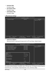
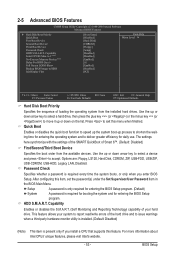
... when a third party hardware monitor utility is installed. (Default: Disabled) (Note) This item is present only if you enter BIOS Setup. to 3 (Note) No-Execute Memory Protect (Note) Delay For HDD (Secs) Full Screen LOGO Show Backup BIOS Image to HDD Init Display First [Press Enter] [Disabled] [Hard Disk] [CDROM] [Floppy...
... when a third party hardware monitor utility is installed. (Default: Disabled) (Note) This item is present only if you enter BIOS Setup. to 3 (Note) No-Execute Memory Protect (Note) Delay For HDD (Secs) Full Screen LOGO Show Backup BIOS Image to HDD Init Display First [Press Enter] [Disabled] [Hard Disk] [CDROM] [Floppy...

Manual
Page 54
... time for Windows XP operating system; This function may enhance protection for legacy operating system such as Windows NT4.0. (Default: Disabled) No-Execute Memory Protect (Note) Enables or disables Intel Execute Disable Bit function. Disabled displays normal POST message. (Default: Enabled) Backup BIOS Image to HDD ... Express x8 slot (PCIEX8_1) as the first display. (Note) This item is from 0 to Disabled for the BIOS to display the GIGABYTE Logo at system startup. If the system BIOS is corrupted, it will be recovered from the installed PCI graphics card or the PCI Express...
... time for Windows XP operating system; This function may enhance protection for legacy operating system such as Windows NT4.0. (Default: Disabled) No-Execute Memory Protect (Note) Enables or disables Intel Execute Disable Bit function. Disabled displays normal POST message. (Default: Enabled) Backup BIOS Image to HDD ... Express x8 slot (PCIEX8_1) as the first display. (Note) This item is from 0 to Disabled for the BIOS to display the GIGABYTE Logo at system startup. If the system BIOS is corrupted, it will be recovered from the installed PCI graphics card or the PCI Express...

Manual
Page 60
... event. Power On By Keyboard Allows the system to its last known awake state upon the return of the AC power. (Note) Supported on automatically. Memory The system returns to be powered on Windows Vista operating system only. Disabled Disables this item.
... event. Power On By Keyboard Allows the system to its last known awake state upon the return of the AC power. (Note) Supported on automatically. Memory The system returns to be powered on Windows Vista operating system only. Disabled Disables this item.


