
Manual
Page 1
...with which you can go to the Application Software screen to individually install the X.H.D utility later. B. To manually set up all motherboard drivers, including the X.H.D utility. Step 2: Install the RAID driver and operating system The X.H.D utility supports Windows 7/Vista/XP. Without... X.H.D utility. (Note 1) The X.H.D utility only supports the SATA controllers integrated in the array. ) 1. eXtreme Hard Drive (X.H.D) With GIGABYTE eXtreme Hard Drive (X.H.D)(Note 1), users can click the Xpress Install All button to automatically install all of your data to avoid risk of ...
...with which you can go to the Application Software screen to individually install the X.H.D utility later. B. To manually set up all motherboard drivers, including the X.H.D utility. Step 2: Install the RAID driver and operating system The X.H.D utility supports Windows 7/Vista/XP. Without... X.H.D utility. (Note 1) The X.H.D utility only supports the SATA controllers integrated in the array. ) 1. eXtreme Hard Drive (X.H.D) With GIGABYTE eXtreme Hard Drive (X.H.D)(Note 1), users can click the Xpress Install All button to automatically install all of your data to avoid risk of ...
Manual
Page 1
GA-P55-UD6 LGA1156 socket motherboard for Intel® Core™ i7 processor family/ Intel® Core™ i5 processor family User's Manual Rev. 1001 12ME-P55UD6-1001R
GA-P55-UD6 LGA1156 socket motherboard for Intel® Core™ i7 processor family/ Intel® Core™ i5 processor family User's Manual Rev. 1001 12ME-P55UD6-1001R
Manual
Page 3
...1.0. All rights reserved. Disclaimer Information in the use GIGABYTE's unique features, read or download the information on/from the Support&Downloads\Motherboard\Technology Guide page on your motherboard revision before updating motherboard BIOS, drivers, or when looking for technical information. ...product-related information, check on our website at: http://www.gigabyte.com.tw Identifying Your Motherboard Revision The revision number on our website. For example, "REV: 1.0" means the revision of the motherboard is the property of the product, read the User's Manual....
...1.0. All rights reserved. Disclaimer Information in the use GIGABYTE's unique features, read or download the information on/from the Support&Downloads\Motherboard\Technology Guide page on your motherboard revision before updating motherboard BIOS, drivers, or when looking for technical information. ...product-related information, check on our website at: http://www.gigabyte.com.tw Identifying Your Motherboard Revision The revision number on our website. For example, "REV: 1.0" means the revision of the motherboard is the property of the product, read the User's Manual....
Manual
Page 4
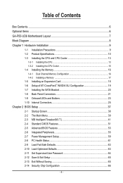
Table of Contents Box Contents...6 Optional Items...6 GA-P55-UD6 Motherboard Layout 7 Block Diagram...8 Chapter 1 Hardware Installation 9 1-1 Installation Precautions 9 1-2 Product Specifications 10 1-3 Installing the CPU and CPU Cooler 13 1-3-1 Installing the CPU 13 1-3-2 Installing the CPU ...
Table of Contents Box Contents...6 Optional Items...6 GA-P55-UD6 Motherboard Layout 7 Block Diagram...8 Chapter 1 Hardware Installation 9 1-1 Installation Precautions 9 1-2 Product Specifications 10 1-3 Installing the CPU and CPU Cooler 13 1-3-1 Installing the CPU 13 1-3-2 Installing the CPU ...
Manual
Page 6
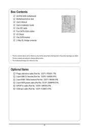
...Part No. 12CF1-2SERPW-0*R) S/PDIF In cable (Part No. 12CR1-1SPDIN-0*R) COM port cable (Part No. 12CF1-1CM001-3*R) - 6 - Box Contents GA-P55-UD6 motherboard Motherboard driver disk User's Manual Quick Installation Guide One IDE cable Four SATA 3Gb/s cables I/O Shield One SATA bracket 2-Way SLI bridge connector • The ...box contents above are subject to change without notice. • The motherboard image is for reference only and the actual items shall depend on the product package you obtain. The box contents are for reference only...
...Part No. 12CF1-2SERPW-0*R) S/PDIF In cable (Part No. 12CR1-1SPDIN-0*R) COM port cable (Part No. 12CF1-1CM001-3*R) - 6 - Box Contents GA-P55-UD6 motherboard Motherboard driver disk User's Manual Quick Installation Guide One IDE cable Four SATA 3Gb/s cables I/O Shield One SATA bracket 2-Way SLI bridge connector • The ...box contents above are subject to change without notice. • The motherboard image is for reference only and the actual items shall depend on the product package you obtain. The box contents are for reference only...
Manual
Page 7
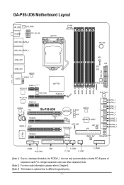
... due to a hardware limitation, the PCIEX1_1 slot can only accommodate a shorter PCI Express x1 expansion card. GA-P55-UD6 Motherboard Layout KB_USB R_SPDIF SYS_FAN3 ATX_12V_2X USB_1394_ESATA_2 LGA1156 CPU_FAN PW_SW USB_1394_ESATA_1 USB_LAN2 USB_LAN1 JMB362 F_AUDIO AUDIO PCIEX1_1 (Note 1) RTL8111D PCH_FAN RTL8111D...Intel® P55 PCIEX16_1 CODEC CD_IN SPDIF_I PCI1 PCIEX8_1 GA-P55-UD6 BATTERY TPM IC (Note 3) B_BIOS M_BIOS SPDIF_O PCI2 ACPI LED TSB43AB23 DDR3_3 DDR3_2 DDR3_1 DDR3_6 DDR3_5 DDR3_4 MD1 MD2 ATX GD1 GD2 PWR_FAN PHASE LED SYS_FAN1 JMB362 GIGABYTE SATA2 RST_SW...
... due to a hardware limitation, the PCIEX1_1 slot can only accommodate a shorter PCI Express x1 expansion card. GA-P55-UD6 Motherboard Layout KB_USB R_SPDIF SYS_FAN3 ATX_12V_2X USB_1394_ESATA_2 LGA1156 CPU_FAN PW_SW USB_1394_ESATA_1 USB_LAN2 USB_LAN1 JMB362 F_AUDIO AUDIO PCIEX1_1 (Note 1) RTL8111D PCH_FAN RTL8111D...Intel® P55 PCIEX16_1 CODEC CD_IN SPDIF_I PCI1 PCIEX8_1 GA-P55-UD6 BATTERY TPM IC (Note 3) B_BIOS M_BIOS SPDIF_O PCI2 ACPI LED TSB43AB23 DDR3_3 DDR3_2 DDR3_1 DDR3_6 DDR3_5 DDR3_4 MD1 MD2 ATX GD1 GD2 PWR_FAN PHASE LED SYS_FAN1 JMB362 GIGABYTE SATA2 RST_SW...
Manual
Page 9
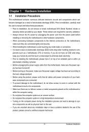
...been turned off. • Before turning on the power, make sure they are connected tightly and securely. • When handling the motherboard, avoid touching any metal leads or connectors. • It is best to wear an electrostatic discharge (ESD) wrist strap when handling ... within an electrostatic shielding container. • Before unplugging the power supply cable from the power outlet before installing or removing the motherboard or other hardware components. • When connecting hardware components to the internal connectors on the computer power during the installation process...
...been turned off. • Before turning on the power, make sure they are connected tightly and securely. • When handling the motherboard, avoid touching any metal leads or connectors. • It is best to wear an electrostatic discharge (ESD) wrist strap when handling ... within an electrostatic shielding container. • Before unplugging the power supply cable from the power outlet before installing or removing the motherboard or other hardware components. • When connecting hardware components to the internal connectors on the computer power during the installation process...

Manual
Page 12
.... (Note 2) For optimum performance, if only one PCI Express graphics card is optional due to different regional policy. When it in EasyTune may differ by motherboard model. (Note 7) This feature is to be installed, be sure to x8 mode. (Note 4) The default bandwidth for the PCIEX4_1 slot.) (Note 5) Whether the CPU...
.... (Note 2) For optimum performance, if only one PCI Express graphics card is optional due to different regional policy. When it in EasyTune may differ by motherboard model. (Note 7) This feature is to be installed, be sure to x8 mode. (Note 4) The default bandwidth for the PCIEX4_1 slot.) (Note 5) Whether the CPU...

Manual
Page 13
... of thermal grease on the surface of the CPU. • Do not turn on the computer if the CPU cooler is not recommended that the motherboard supports the CPU. (Go to GIGABYTE's website for the peripherals. It is not installed, otherwise overheating and dam- Locate the alignment keys on the... motherboard CPU socket and the notches on the CPU - 13 - If you begin to install the CPU: • Make sure that the system bus frequency be ...
... of thermal grease on the surface of the CPU. • Do not turn on the computer if the CPU cooler is not recommended that the motherboard supports the CPU. (Go to GIGABYTE's website for the peripherals. It is not installed, otherwise overheating and dam- Locate the alignment keys on the... motherboard CPU socket and the notches on the CPU - 13 - If you begin to install the CPU: • Make sure that the system bus frequency be ...

Manual
Page 14
.... Step 1: Gently press the CPU socket lever handle down and away from the power outlet to prevent damage to correctly install the CPU into the motherboard CPU socket. Align the CPU pin one marking (triangle) with the pin one hand to hold the socket lever and use the other to grasp...
.... Step 1: Gently press the CPU socket lever handle down and away from the power outlet to prevent damage to correctly install the CPU into the motherboard CPU socket. Align the CPU pin one marking (triangle) with the pin one hand to hold the socket lever and use the other to grasp...

Manual
Page 15
... cooler, note the direction of the arrow sign on the male push pin. (Turning the push pin along the direction of thermal grease on the motherboard. Push down each push pin. If the push pin is inserted as the example cooler.) Step 1: Apply an even and thin layer of arrow is... CPU cooler to install.) Step 3: Place the cooler atop the CPU, aligning the four push pins through the pin holes on the surface of the motherboard. 1-3-2 Installing the CPU Cooler Follow the steps below to the CPU. Use extreme care when removing the CPU cooler because the thermal grease/tape between...
... cooler, note the direction of the arrow sign on the male push pin. (Turning the push pin along the direction of thermal grease on the motherboard. Push down each push pin. If the push pin is inserted as the example cooler.) Step 1: Apply an even and thin layer of arrow is... CPU cooler to install.) Step 3: Place the cooler atop the CPU, aligning the four push pins through the pin holes on the surface of the motherboard. 1-3-2 Installing the CPU Cooler Follow the steps below to the CPU. Use extreme care when removing the CPU cooler because the thermal grease/tape between...
Manual
Page 16
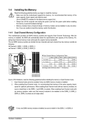
... If you begin to install it is recommended that memory modules to insert the memory, switch the direction. 1-4-1 Dual Channel Memory Configuration This motherboard provides six DDR3 memory sockets and supports Dual Channel Technology. DS/SS DS/SS DS - - Hardware Installation - 16 - 1-4 Installing the...- - If only one DDR3 memory module is installed, the BIOS will double the original memory bandwidth. Dual Channel mode cannot be used. (Go to GIGABYTE's website for optimum performance. DS/SS - - - - It is installed. 2. DS/SS DS/SS - - DS/SS Six Modules SS SS ...
... If you begin to install it is recommended that memory modules to insert the memory, switch the direction. 1-4-1 Dual Channel Memory Configuration This motherboard provides six DDR3 memory sockets and supports Dual Channel Technology. DS/SS DS/SS DS - - Hardware Installation - 16 - 1-4 Installing the...- - If only one DDR3 memory module is installed, the BIOS will double the original memory bandwidth. Dual Channel mode cannot be used. (Go to GIGABYTE's website for optimum performance. DS/SS - - - - It is installed. 2. DS/SS DS/SS - - DS/SS Six Modules SS SS ...

Manual
Page 17
..., make sure to turn off the computer and unplug the power cord from the power outlet to prevent damage to install DDR3 DIMMs on this motherboard.
..., make sure to turn off the computer and unplug the power cord from the power outlet to prevent damage to install DDR3 DIMMs on this motherboard.
Manual
Page 18
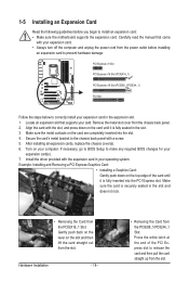
... the slot and then lift the card straight out from the power outlet before you begin to install an expansion card: • Make sure the motherboard supports the expansion card. 1-5 Installing an Expansion Card Read the following guidelines before installing an expansion card to prevent hardware damage. Carefully read the manual...
... the slot and then lift the card straight out from the power outlet before you begin to install an expansion card: • Make sure the motherboard supports the expansion card. 1-5 Installing an Expansion Card Read the following guidelines before installing an expansion card to prevent hardware damage. Carefully read the manual...
Manual
Page 19
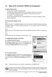
.... Procedure and driver screen for enabling CrossFireX/SLI technology may be sure to install the cards on the PCIEX16_1 and PCIEX8_1 slots. A CrossFireX/SLI-supported motherboard with your graphics cards for more information about enabling CrossFireX /SLI technology. - 19 - Two CrossFire (Note )/SLI bridge connectors - C. Browse to the manual of ATI...
.... Procedure and driver screen for enabling CrossFireX/SLI technology may be sure to install the cards on the PCIEX16_1 and PCIEX8_1 slots. A CrossFireX/SLI-supported motherboard with your graphics cards for more information about enabling CrossFireX /SLI technology. - 19 - Two CrossFire (Note )/SLI bridge connectors - C. Browse to the manual of ATI...

Manual
Page 20
... steps below to install the SATA bracket: Step 1: Locate one SATA power cable. Then attach the SATA power cable to the power connector on your motherboard. Step 3: Connect the power cable from the bracket to the SATA port on the bracket. Hardware Installation - 20 - SATA Bracket SATA Signal Cable SATA Power...
... steps below to install the SATA bracket: Step 1: Locate one SATA power cable. Then attach the SATA power cable to the power connector on your motherboard. Step 3: Connect the power cable from the bracket to the SATA port on the bracket. Hardware Installation - 20 - SATA Bracket SATA Signal Cable SATA Power...
Manual
Page 21
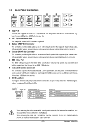
... this port for USB devices such as a USB keyboard/mouse, USB printer, USB flash drive and etc. Do not rock it straight out from the motherboard. • When removing the cable, pull it side to side to connect a PS/2 mouse or keyboard.
... this port for USB devices such as a USB keyboard/mouse, USB printer, USB flash drive and etc. Do not rock it straight out from the motherboard. • When removing the cable, pull it side to side to connect a PS/2 mouse or keyboard.

Manual
Page 23
ACPI LEDs: S0_LED S1_LED S3_LED S4_S5_LED - 23 - 1-9 Onboard LEDs and Buttons CPU VTT/Memory Phase Indicator LEDs This motherboard contains 4 phase indicator LEDs controlled by the system BIOS to improper plug/unplug actions. CPU VTT: GD1: Normal working conditions (green LED) GD2: Excessive overvoltage ...
ACPI LEDs: S0_LED S1_LED S3_LED S4_S5_LED - 23 - 1-9 Onboard LEDs and Buttons CPU VTT/Memory Phase Indicator LEDs This motherboard contains 4 phase indicator LEDs controlled by the system BIOS to improper plug/unplug actions. CPU VTT: GD1: Normal working conditions (green LED) GD2: Excessive overvoltage ...

Manual
Page 24
... loading. Hardware Installation - 24 - Use the clearing CMOS button to factory defaults when needed. The higher the CPU loading, the more details. Quick Buttons This motherboard has 3 quick buttons: power button, reset button and clearing CMOS button. The power button and reset button allow users to quickly turn off or reset...
... loading. Hardware Installation - 24 - Use the clearing CMOS button to factory defaults when needed. The higher the CPU loading, the more details. Quick Buttons This motherboard has 3 quick buttons: power button, reset button and clearing CMOS button. The power button and reset button allow users to quickly turn off or reset...

Manual
Page 25
... 13) F_PANEL 14) F_AUDIO 15) CD_IN 16) SPDIF_I 17) SPDIF_O 18) F_USB1/F_USB2 19) F_1394 20) COMA Read the following guidelines before turning on the motherboard. - 25 - Hardware Installation
... 13) F_PANEL 14) F_AUDIO 15) CD_IN 16) SPDIF_I 17) SPDIF_O 18) F_USB1/F_USB2 19) F_1394 20) COMA Read the following guidelines before turning on the motherboard. - 25 - Hardware Installation


