Manual
Page 5
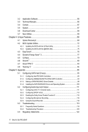
...Q-Share...79 4-6 Smart 6™ ...80 4-7 Smart TPM j 83 4-8 Teaming j 84 Chapter 5 Appendix...85 5-1 Configuring SATA Hard Drive(s 85 5-1-1 Configuring Intel P55 SATA Controllers 85 5-1-2 Configuring JMB362/GIGABYTE SATA2 SATA Controller 93 5-1-3 Making a SATA RAID/AHCI Driver Diskette 99 5-1-4 Installing the SATA RAID/AHCI Driver and Operating System 100 5-2 Configuring Audio... Recording 116 5-2-5 Using the Sound Recorder 118 5-3 Troubleshooting 119 5-3-1 Frequently Asked Questions 119 5-3-2 Troubleshooting Procedure 120 5-4 Regulatory Statements 122 j Only for GA-P55-UD4P. - 5 -
...Q-Share...79 4-6 Smart 6™ ...80 4-7 Smart TPM j 83 4-8 Teaming j 84 Chapter 5 Appendix...85 5-1 Configuring SATA Hard Drive(s 85 5-1-1 Configuring Intel P55 SATA Controllers 85 5-1-2 Configuring JMB362/GIGABYTE SATA2 SATA Controller 93 5-1-3 Making a SATA RAID/AHCI Driver Diskette 99 5-1-4 Installing the SATA RAID/AHCI Driver and Operating System 100 5-2 Configuring Audio... Recording 116 5-2-5 Using the Sound Recorder 118 5-3 Troubleshooting 119 5-3-1 Frequently Asked Questions 119 5-3-2 Troubleshooting Procedure 120 5-4 Regulatory Statements 122 j Only for GA-P55-UD4P. - 5 -

Manual
Page 7
... F_AUDIO SYS_FAN1 PCIEX1_1(Note) PCIEX16 RTL8111D j PCIEX1_2 CD_IN SPDIF_I SPDIF_O CODEC PCIEX1_3 PCIEX8 PCI1 BATTERY TPM IC j TSB43AB23 GA-P55-UD4P / GA-P55-UD4 DDR3_2 DDR3_1 PHASE LED ATX PWR_FAN IDE DDR3_4 DDR3_3 GIGABYTE SATA2 B_BIOS Intel® P55 M_BIOS SYS_FAN2 PCH_FAN CLR_CMOS GSATA2_1 GSATA2_0 SATA2_1 SATA2_0 SATA2_3 SATA2_2 SATA2_5 SATA2_4 IT8720 PCI2 LPT COMA FDD F1_1394...
... F_AUDIO SYS_FAN1 PCIEX1_1(Note) PCIEX16 RTL8111D j PCIEX1_2 CD_IN SPDIF_I SPDIF_O CODEC PCIEX1_3 PCIEX8 PCI1 BATTERY TPM IC j TSB43AB23 GA-P55-UD4P / GA-P55-UD4 DDR3_2 DDR3_1 PHASE LED ATX PWR_FAN IDE DDR3_4 DDR3_3 GIGABYTE SATA2 B_BIOS Intel® P55 M_BIOS SYS_FAN2 PCH_FAN CLR_CMOS GSATA2_1 GSATA2_0 SATA2_1 SATA2_0 SATA2_3 SATA2_2 SATA2_5 SATA2_4 IT8720 PCI2 LPT COMA FDD F1_1394...

Manual
Page 8
...x1 x1 (100 MHz) x1 3 PCI Express x1 2 SATA 3Gb/s ATA-133/100/66/33 IDE Channel PCI Bus GIGABYTE SATA2 TSB43AB23 3 IEEE 1394a LGA1156 CPU CPU CLK+/- (133 MHz) DDR3 2200/1333/1066/800 MHz Dual Channel Memory DMI Interface Intel&#...174; P55 PCI Express Bus x1 2 SATA 3Gb/s JMB362 Dual BIOS 6 SATA 3Gb/s 14 USB Ports CODEC LPC Bus IT8720 Floppy COM Port... Speaker Out MIC Line Out Line In S/PDIF In S/PDIF Out 2 PCI PCI CLK (33 MHz) j Only for GA-P55-UD4P. - 8 -
...x1 x1 (100 MHz) x1 3 PCI Express x1 2 SATA 3Gb/s ATA-133/100/66/33 IDE Channel PCI Bus GIGABYTE SATA2 TSB43AB23 3 IEEE 1394a LGA1156 CPU CPU CLK+/- (133 MHz) DDR3 2200/1333/1066/800 MHz Dual Channel Memory DMI Interface Intel&#...174; P55 PCI Express Bus x1 2 SATA 3Gb/s JMB362 Dual BIOS 6 SATA 3Gb/s 14 USB Ports CODEC LPC Bus IT8720 Floppy COM Port... Speaker Out MIC Line Out Line In S/PDIF In S/PDIF Out 2 PCI PCI CLK (33 MHz) j Only for GA-P55-UD4P. - 8 -

Manual
Page 10
.... Support for SATA RAID 0, RAID 1, RAID 5, and RAID 10 GIGABYTE SATA2 chip: - 1 x IDE connector supporting ATA-133/100/66/33 and up to 2 IDE devices - 2 x SATA 3Gb/s connectors (GSATA2_0, GSATA2_1) supporting up to 1 floppy disk drive j Only for GA-P55-UD4P. Support for SATA RAID 0, RAID 1, and JBOD JMB362 SATA2 chip: - 2 x eSATA...
.... Support for SATA RAID 0, RAID 1, RAID 5, and RAID 10 GIGABYTE SATA2 chip: - 1 x IDE connector supporting ATA-133/100/66/33 and up to 2 IDE devices - 2 x SATA 3Gb/s connectors (GSATA2_0, GSATA2_1) supporting up to 1 floppy disk drive j Only for GA-P55-UD4P. Support for SATA RAID 0, RAID 1, and JBOD JMB362 SATA2 chip: - 2 x eSATA...

Manual
Page 83
... key using Smart TPM: 1. Unique Features Loss of complicated configurations. It's recommended that you use software interface to the Install New Utilities menu. Instructions for GA-P55-UD4P. - 83 - Be sure to memorize this setting) to your computer, the Infineon Security Platform icon , which your PSD will appear in the BIOS main menu... how to access Smart TPM. You will store the encrypted TPM User Password in sequence: Step 1: As the computer starts, enter the BIOS Setup program. GIGABYTE is not liable for loss of encrypted data as the Smart TPM user key.
... key using Smart TPM: 1. Unique Features Loss of complicated configurations. It's recommended that you use software interface to the Install New Utilities menu. Instructions for GA-P55-UD4P. - 83 - Be sure to memorize this setting) to your computer, the Infineon Security Platform icon , which your PSD will appear in the BIOS main menu... how to access Smart TPM. You will store the encrypted TPM User Password in sequence: Step 1: As the computer starts, enter the BIOS Setup program. GIGABYTE is not liable for loss of encrypted data as the Smart TPM user key.

Manual
Page 93
... Setup menus described in system BIOS Setup. Configuring SATA controller mode in BIOS Setup Make sure to the hard drive. Controller Connectors JMB362 eSATA ports GIGABYTE GSATA2_0/1 SATA2 BIOS Settings Set eSATA Controller to Enabled Set eSATA Ctrl Mode to RAID Set GSATA 0_1/IDE Controller to Enabled Set GSATA 0_1... below for configuring different SATA Controllers for the SATA controllers and their corresponding SATA ports. Then connect the power connector from the exact settings for GA-P55-UD4P. 5-1-2 Configuring JMB362/GIGABYTE SATA2 SATA Controller A.
... Setup menus described in system BIOS Setup. Configuring SATA controller mode in BIOS Setup Make sure to the hard drive. Controller Connectors JMB362 eSATA ports GIGABYTE GSATA2_0/1 SATA2 BIOS Settings Set eSATA Controller to Enabled Set eSATA Ctrl Mode to RAID Set GSATA 0_1/IDE Controller to Enabled Set GSATA 0_1... below for configuring different SATA Controllers for the SATA controllers and their corresponding SATA ports. Then connect the power connector from the exact settings for GA-P55-UD4P. 5-1-2 Configuring JMB362/GIGABYTE SATA2 SATA Controller A.


